Table of Contents
Advertisement
Advertisement
Table of Contents

Related Manuals for ABB A43


Summary of Contents for ABB A43
- Page 1 A43/A44 User Manual...
- Page 2 A43/A44 User Manual Document ID: 2CMC484001M0201 Revision: C 2018-09-26 A43/A44 2CMC48001M0201 User Manual Revision: C...
- Page 3 All cables and sealing must be checked on a regular basis, if any sealing is broken the security and safety can no longer be ensured and ABB Ltd and its affiliates are not liable for damages and/or losses related to such disturbances, security breaches, unauthorized access, interference, intrusion, leakage and/or theft of data or information.
- Page 4 ABB AB is a registered trademark of the ABB Group. All other brand or product Trademarks names mentioned in this document may be trademarks or registered trademarks of their respective holders. ABB SpA Contact Via Dell’industria, 18 20010 – Vittuone - Milano...
-
Page 5: Table Of Contents
Setting Demand ........................ 44 4.1.18 Resetting Resettable Registers ..................44 Technical Description ......................45 Energy Values ........................... 46 Instrumentation ........................48 Harmonics ..........................50 5.3.1 Measuring Harmonics ...................... 52 Alarm ............................54 Inputs and Outputs ........................56 2CMC48001M0201 A43/A44 Revision: C User Manual... - Page 6 9.10.1 Previous values ....................... 143 9.10.2 Demand .......................... 144 9.10.3 Load profile ........................148 9.10.4 Alarms ..........................149 9.10.5 Inputs and outputs ......................153 9.10.6 Tariffs ..........................156 9.10.7 Daylight Savings Time ..................... 165 A43/A44 2CMC48001M0201 User Manual Revision: C...
- Page 7 10.5.27 Reset demand, previous values, load profile and logs ........... 287 10.5.28 Reset resettable active energy import ................288 10.5.29 Reset resettable active energy export ................288 10.5.30 Reset resettable reactive energy import................ 289 10.5.31 Reset resettable reactive energy export ................ 289 2CMC48001M0201 A43/A44 Revision: C User Manual...
- Page 8 10.5.33 Set write access level ..................... 290 10.5.34 Set tariff source ......................291 10.5.35 Set CO2 conversion factor ....................291 10.5.36 Set currency conversion factor ..................292 Troubleshooting ........................293 11.1 Error, warnings and information codes ................. 294 A43/A44 2CMC48001M0201 User Manual Revision: C...
-
Page 9: Product Overview
This chapter describes the parts of the meter and the different meter types. The following topics are covered in this chapter: In this chapter Product Overview ........................9 Meter Parts ..........................10 Meter Types ..........................12 2CMC48001M0201 A43/A44 Revision: C User Manual... -
Page 10: Meter Parts
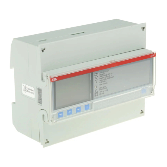
Protective cover with printed wiring diagram on the inside Terminal block Terminal for all voltages and currents Sealable cover To protect the LCD and seal the set button Product data Contains data about the meter type A43/A44 2CMC48001M0201 User Manual Revision: C... - Page 11 Toggle up (toggle left in the main menu) Exit button Exit to the previous menu or toggle between default and main menu. Display LCD for meter reading Optical communication interface For IR communication Sealing 2CMC48001M0201 A43/A44 Revision: C User Manual...
-
Page 12: Meter Types
Product Overview 1.2 Meter Types The A43/A44 meters are divided into two main groups: Main groups • Direct connected meters for currents up to maximum 80A. • Transformer connected meters for currents > 80A using external current transformers with secondary current up to maximum 6A and optional voltage transformers. - Page 13 3-element metering 2-element metering 1-element metering Pulse output Protective class II Declaration of product safety Type designation Serial number Accuracy active energy Accuracy reactive energy Voltage Current Frequency LED pulse frequency Pulse frequency Temperature range 2CMC48001M0201 A43/A44 Revision: C User Manual...
- Page 14 Interface - RS-485 port Interface - M-Bus IEC approved + MID approved and verified IEC approved + GOST approved and verified IEC approved CCC approved (China) ABB standard version Industrial version Rail application version ABB standard version Customer specific version 1 ………………………...
-
Page 15: Installation
2 Installation Overview This chapter describes how to mount the A43/A44 meters and how to connect them to an electricity network. The chapter also contains information about how to perform a basic configuration of the meter and how to connect I/O and communication options. -
Page 16: Mounting The Meter
For further information about accessories, refer to the Main Catalog (2CMC480001C0201). The A43/A44 meters are intended to be mounted on a DIN-rail (DIN 50022). If DIN-rail mounted this method of mounting is used no extra accessories are needed and the meter is fastened by snapping the DIN-rail lock onto the rail. - Page 17 Installation Flush mounted To flush-mount the meter a flush-mount kit should be used. Flush-mount kit The following picture shows a flush-mount kit. 2CMC48001M0201 A43/A44 Revision: C User Manual...
-
Page 18: Environmental Considerations
-40°C - +70°C. In order to work properly the product should not exposed to humidity exceeding the specified 75% yearly average, 95% on 30 days/year. The product is made for indoor use only. A43/A44 2CMC48001M0201 User Manual Revision: C... -
Page 19: Installing The Meter
(0.25 Nm). Then connect to an external power supply (max 240V). If communication is used, connect the cables according to the wiring diagram that is printed on the meter and tighten the screws (0.25 Nm). Verify the installation 2CMC48001M0201 A43/A44 Revision: C User Manual... -
Page 20: Configuring The Meter
Check the settings of the meter to see if they need to be reconfigured. Parameter Direct connected meters Transformer connected meters Clock Ratios VT Ratios CT Number of wires Pulse frequency 100 impulses / kWh (kvarh) 10 impulses / kWh (kvarh) Pulse length 100 ms 100 ms A43/A44 2CMC48001M0201 User Manual Revision: C... -
Page 21: Wiring Diagrams
The following diagram shows a 4-wire connection of a direct connected 3-phase meter: 3-wire connection The following diagram shows a 3-wire connection of a direct connected 3-phase meter: 2-wire connection The following diagram shows a 2-wire connection of a direct connected 3-phase meter: 2CMC48001M0201 A43/A44 Revision: C User Manual... -
Page 22: Transformer Connected Meters Without Voltage Transformer
The following diagram shows a 4-wire connection of a transformer connected 3- phase meter: 3-wire connection The following diagram shows a 3-wire connection of a transformer connected 3- phase meter: The following diagram shows a 2-wire connection of a transformer connected 3-phase 2-wire connection meter: A43/A44 2CMC48001M0201 User Manual Revision: C... -
Page 23: Transformer Connected Meters With Voltage Transformer
The following diagram shows a 4-wire connection of a transformer connected 3- phase meter with voltage transformers: 3-wire connection The following diagram shows a 3-wire connection of a transformer connected 3- phase meter with voltage transformers: 2CMC48001M0201 A43/A44 Revision: C User Manual... -
Page 24: Inputs/Outputs
Installation 2-wire connection The following diagram shows a 2-wire connection of a transformer connected 3- phase meter with voltage transformers: 2.4.4 Inputs/outputs 2 outputs, 2 inputs 4 configurable Inputs/outputs A43/A44 2CMC48001M0201 User Manual Revision: C... -
Page 25: Communication
Installation 1 output Out1 1 output, 1 Input (on A44 xxx x1x) 2.4.5 Communication RS-485 M-Bus 2CMC48001M0201 A43/A44 Revision: C User Manual... -
Page 26: User Interface
User Interface 3 User Interface This chapter describes the different display views and the menu structure. Overview In this chapter The following topics are covered in this chapter: User Interface ........................26 Display ............................27 A43/A44 2CMC48001M0201 User Manual Revision: C... -
Page 27: Display
Measures the total exported reactive en- ergy 6/25 kvarh REACT.NRG.NET.TOT Measures the total net reactive energy 7/25 kVAh APP.NRG.IMP.TOT Measures the total imported apparent energy 8/25 kVAh APP.NRG.EXP.TOT Measures the total exported apparent energy 2CMC48001M0201 A43/A44 Revision: C User Manual... - Page 28 Measures the ex- ported reactive en- ergy for tariff 2 24/25 kvarh REACT.NRG.EXP.TAR3 Measures the ex- ported reactive en- ergy for tariff 3 25/25 kvarh REACT.NRG.EXP.TAR4 Measures the ex- ported reactive en- ergy for tariff 4 A43/A44 2CMC48001M0201 User Manual Revision: C...
- Page 29 The following image shows an example of the layout of the main menu: Main menu icons Depending on the meter type all or a subset of the following icons may be avail- able in the display: Icon Explanation Energy registers Instantaneous values Stored values Harmonics 2CMC48001M0201 A43/A44 Revision: C User Manual...
- Page 30 Reactive Energy Im- Current Quadrant Pulse LED port Tariffs Reactive Energy Ex- Tariff port Tariffs Resettable Active En- Previous Values ergy Import Total Resettable Active En- Load profiles ergy Export Total Resettable Reactive Demand Energy Import Total A43/A44 2CMC48001M0201 User Manual Revision: C...
- Page 31 User Interface Resettable Reactive Resettable regis- Energy Import Total ters Currency 2CMC48001M0201 A43/A44 Revision: C User Manual...
-
Page 32: Meter Settings
4.1.13 Setting Pulse LED ......................42 4.1.14 Setting Tariff ........................42 4.1.15 Setting Previous Values ....................43 4.1.16 Setting Load Profile ......................43 4.1.17 Setting Demand ........................ 44 4.1.18 Resetting Resettable Registers ..................44 A43/A44 2CMC48001M0201 User Manual Revision: C... -
Page 33: Settings And Configurations
To set the date, perform the following steps: 1. Choose the Settings icon in the main menu, press 2. Choose “Clock”, press 3. The display will now show the date. 4. Set the date. 2CMC48001M0201 A43/A44 Revision: C User Manual... -
Page 34: Setting Time
Active energy imported Act.Nrg.Exp on the display Active energy exported React.Nrg.Imp on the display Reactive energy imported React.Nrg.Exp on the display Reactive energy exported Inactive on the display Inactive 3. Set the energy type. A43/A44 2CMC48001M0201 User Manual Revision: C... -
Page 35: Setting I/O
• Tariff out • Always on • Always off • Alarm out 4 static I/Os • Communication out (Comm.out on display) • Pulse out (Pul.out on display) • Tariff out • Always on • Always off 2CMC48001M0201 A43/A44 Revision: C User Manual... -
Page 36: Setting Alarm
10.The first alarm is now fully configured. Depending on the meter type, up to 25 alarms can be set. If your meter supports multiple alarms, use to set the remaining alarms the same way as the first alarm was configured. A43/A44 2CMC48001M0201 User Manual Revision: C... - Page 37 Power factor L1 0.000-0.999 Power factor L2 0.000-0.999 Power factor L3 0.000-0.999 Table: 4:4 4 configurable I/Os 4 static I/Os 1 static I/O No output No output No output Out 1 Out 1 Out 1 2CMC48001M0201 A43/A44 Revision: C User Manual...
-
Page 38: Setting Currency/Co
RS-485 communication depending on protocol, perform the following steps: Step EQ-Bus Modbus Choose the Settings icon in the Choose the Settings icon in the main menu, press main menu, press Choose communication interface. Choose communication inter- face. Choose EQ-Bus. Choose Modbus. A43/A44 2CMC48001M0201 User Manual Revision: C... -
Page 39: Setting Ir Side
Set the access level. Set Oct. TO. i. EQ-Bus is a communication protocol designed for internal communication with ABB meters. The protocol is based on the following standards; IEC 62056-42, IEC 62056-46, IEC 62056- 53, IEC 62056-61, IEC 62056-62. - Page 40 Meter Settings A43/A44 2CMC48001M0201 User Manual Revision: C...
- Page 41 2400, used Even 4800, through 9600, RS-485) 19200, 38400, 57600, 115200 M-Bus Open, Active, Always, Yes, No 2400, 1-250 (when Password, Not Active Never, 4800, used Closed When 9600, through not OK 19200 IR-Side) 2CMC48001M0201 A43/A44 Revision: C User Manual...
-
Page 42: Setting Upgrade Consent
Choose the Settings icon in Choose the Settings icon in Choose the Set- the main menu, press the main menu, press tings icon in the main menu, press Choose “Tariff”, press Choose “Tariff”, press Choose “Tariff”, press A43/A44 2CMC48001M0201 User Manual Revision: C... -
Page 43: Setting Previous Values
Active Energy Exported Total Act.Exp.Tot 1 hours Reactive Energy Imported Total React.Imp.Tot 1 hours Reactive Energy Exported Total React.Exp.Tot 1 hours Input Counter 1 Inp.Ctr 1 1 hours Input Counter 2 Inp.Ctr 2 1 hours 2CMC48001M0201 A43/A44 Revision: C User Manual... -
Page 44: Setting Demand
On the display Active Energy Imported Total Act.Imp Active Energy Exported Total Act.Exp Reactive Energy Imported Total Rea.Imp Reactive Energy Exported Total Rea.Exp Reset all 4. Toggle through the pages and reset the desired registers. A43/A44 2CMC48001M0201 User Manual Revision: C... -
Page 45: Technical Description
Event Log .......................... 63 5.7.3 Net Quality Log ......................... 64 5.7.4 Audit Log .......................... 64 5.7.5 Settings Log ........................65 5.7.6 Event codes ........................65 Demand ............................ 67 Previous Values ........................70 5.10 Load Profile ..........................72 2CMC48001M0201 A43/A44 Revision: C User Manual... -
Page 46: Energy Values
The meter can however contain more digits internally, which can be read out via communication if the meter is equipped with a communication interface. See the example below where the value 2483756 is displayed, while the internal register contains 192483756.6. A43/A44 2CMC48001M0201 User Manual Revision: C... - Page 47 Technical Description Image The following picture shows a display with fixed unit and numbers of decimals: 2CMC48001M0201 A43/A44 Revision: C User Manual...
-
Page 48: Instrumentation
Technical Description 5.2 Instrumentation Instrumentation The following table shows the complete instrumentation functions of the A43 and functions A44 meters. Depending on the meter type all or a subset of the following func- tions are available. Instrumentation 3-phase, 4-wire 3-phase, 3-wire... - Page 49 The accuracy of all instrumentation data except the frequency and voltage and current phase-angles is the same as the stated energy metering accuracy. The ac- curacy for the voltage and current phase-angles is 2 degrees and 0.5 % for the frequency. 2CMC48001M0201 A43/A44 Revision: C User Manual...
-
Page 50: Harmonics
However, the origin of harmonics in the voltage are non-linear loads. A43/A44 2CMC48001M0201 User Manual Revision: C... - Page 51 • Install filters to protect to protect loads that are sensitive to voltage harmonics. • Oversize generators, motors and transformers to better cope with harmonics. • Substitute equipment for equipment that generates less current harmonics and is less sensitive to voltage harmonics. 2CMC48001M0201 A43/A44 Revision: C User Manual...
-
Page 52: Measuring Harmonics
To measurement get a valid measurement the meter uses a retry scheme. If the retry scheme does not give a valid measurement the harmonic will be marked as "not available". A43/A44 2CMC48001M0201 User Manual Revision: C... - Page 53 ± 30% ± 2.5% ± 5.0% ± 10% ± 20% ± 30% ± 2.5% ± 5.0% ± 10% ± 20% ± 30% * For distortion levels below 1% the absolute uncertainty is ± 0.5%. 2CMC48001M0201 A43/A44 Revision: C User Manual...
-
Page 54: Alarm
If the activation level is lower than the deactivation level, the alarm is activated when the value of the monitored quantity is lower than the activation level. A43/A44 2CMC48001M0201 User Manual... - Page 55 Technical Description 2CMC48001M0201 A43/A44 Revision: C User Manual...
-
Page 56: Inputs And Outputs
Input coding, meters with 4 tariffs The coding of the inputs is binary. The following table describes the default cod-ing. Input 4 Input 3 Tariff = T1 = T2 = T3 = T4 A43/A44 2CMC48001M0201 User Manual Revision: C... -
Page 57: Pulse Outputs
In worst case the relay may be closed at all times. To avoid this problem a calculation should be made to work out the maximum pulse frequency allowed at a particular site based upon an estimated maximum power and the meter’s pulse output data. 2CMC48001M0201 A43/A44 Revision: C User Manual... - Page 58 Technical Description A43/A44 2CMC48001M0201 User Manual Revision: C...
- Page 59 50) and pulse width 100 ms and required pulse pause 30 ms the maximum allowed pulse frequency will be: 1000 * 3600 / 6300 / 300 / 3 / (0.030 + 0.100) = 6.16 impulses / kWh (kvarh) 2CMC48001M0201 A43/A44 Revision: C User Manual...
-
Page 60: Internal Clock
• Previous values • Event log • Outputs controlled by time • Tariff control Backup of clock In case of power failure a super capacitor backs up the clock for at least 48 hours. A43/A44 2CMC48001M0201 User Manual Revision: C... - Page 61 Technical Description 2CMC48001M0201 A43/A44 Revision: C User Manual...
-
Page 62: Logs
• Program CRC Error - Error when checking firmware consistency. • Persistent Storage Error - Data stored in long-term memory is corrupt. • RTC Circuit Error - Error when trying to read date and time from real-time clock. A43/A44 2CMC48001M0201 User Manual Revision: C... -
Page 63: Event Log
• Alarm Apparent power L1 • Alarm Apparent power L2 • Alarm Apparent power L3 • Alarm Power Factor Total • Alarm Power Factor L1 • Alarm Power Factor L2 • Alarm Power Factor L3 2CMC48001M0201 A43/A44 Revision: C User Manual... -
Page 64: Net Quality Log
• Active Energy import L3 • Active Energy import Tariff 1 • Active Energy import Tariff 2 • Active Energy import Tariff 3 • Active Energy import Tariff 4 • Active Energy Export • Firmware Upgrade status A43/A44 2CMC48001M0201 User Manual Revision: C... -
Page 65: Settings Log
1005 Negative Power Element 2 Warning 1006 Negative Power Element 3 Warning 1007 Negative Total power Warning 1008 Frequency Warning 1010 Date Not Set Warning 1011 Time Not Set Warning 2013 Alarm 1 active 2CMC48001M0201 A43/A44 Revision: C User Manual... - Page 66 Alarm 17 active 2030 Alarm 18 active 2031 Alarm 19 active 2032 Alarm 20 active 2033 Alarm 21 active 2034 Alarm 22 active 2035 Alarm 23 active 2036 Alarm 24 active 2037 Alarm 25 active A43/A44 2CMC48001M0201 User Manual Revision: C...
-
Page 67: Demand
It is also possible to erase all stored periods by sending a “Reset Demand” com-mand via communication. If the time is set backward within an interval the calculation of demand for that interval is restarted if the channel is configured to store a maximum value (as the 2CMC48001M0201 A43/A44 Revision: C User Manual... - Page 68 The selectable sub-interval times for demand is a subset of the interval times and evenly divisible with the selected interval time. A43/A44 2CMC48001M0201 User Manual Revision: C...
- Page 69 The value is the mean value of the interval. The unit for the pulse input counters are pulses per hour (for example if 2 pulses were registered in a 15 minute interval the value for the interval will be 8 pulses per hour) 2CMC48001M0201 A43/A44 Revision: C User Manual...
-
Page 70: Previous Values
REACTIVE ENERGY IMPORT TARIFF3 ACTIVE ENERGY EXPORT L1 REACTIVE ENERGY IMPORT TARIFF4 ACTIVE ENERGY EXPORT L2 REACTIVE ENERGY EXPORT TARIFF1 ACTIVE ENERGY EXPORT L3 REACTIVE ENERGY EXPORT TARIFF2 REACTIVE ENERGY IMPORT TOTAL REACTIVE ENERGY EXPORT TARIFF3 A43/A44 2CMC48001M0201 User Manual Revision: C... - Page 71 PORT TOTAL RESETTABLE REACTIVE ENERGY IM- ACTIVE ENERGY CURRENCY CONVER- PORT TOTAL SION RESETTABLE REACTIVE ENERGY EX- ACTIVE ENERGY CO2 CONVERSION PORT TOTAL ACTIVE ENERGY IMPORT TARIFF1 PULSE INPUT COUNTERS ACTIVE ENERGY IMPORT TARIFF2 2CMC48001M0201 A43/A44 Revision: C User Manual...
-
Page 72: Load Profile
Each channel can be assigned a number of snapshots. A total of 40 000 snapshots can be stored in a load profile. All channels in a load profile share the same mem-ory area, which means that one channel can store 40 000 snapshots if no other A43/A44 2CMC48001M0201 User Manual... - Page 73 • Interval is longer or shorter than defined length • Power outage occurred during interval • Overflow in data • Time was changed during interval • Data not available • Error in data 2CMC48001M0201 A43/A44 Revision: C User Manual...
- Page 74 POWER FACTOR L1* APPARENT ENERGY EXPORT TOTAL POWER FACTOR L2* APPARENT ENERGY IMPORT L1 POWER FACTOR L3* APPARENT ENERGY IMPORT L2 PULSE INPUT COUNTERS APPARENT ENERGY IMPORT L3 *The values are mean values of the intervals. A43/A44 2CMC48001M0201 User Manual Revision: C...
- Page 75 Technical Description 2CMC48001M0201 A43/A44 Revision: C User Manual...
-
Page 76: Technical Data
6 Technical data This chapter contains technical data and product drawings. Overview In this chapter The following topics are covered in this chapter: Technical data ........................76 Technical Specifications ......................77 Physical dimensions ......................... 81 A43/A44 2CMC48001M0201 User Manual Revision: C... -
Page 77: Technical Specifications
Technical data 6.1 Technical Specifications Specifications for A43 direct connected meters Voltage/current inputs Nominal voltage 3x230/400 V AC Voltage range 3x57.7-288/100-500 V AC (-20%-+15%) Power dissipation voltage circuits 1.9 VA (0.8 W) total at 230 V AC 0.007 VA (0.007 W) per phase at I... - Page 78 Power dissipation voltage circuits 1.9 VA (0.8 W) total at 230 V AC 0.001 VA (0.001 W) per phase at I Power dissipation current circuits Terminal wire area 0.5 - 10 mm² Recommended tightening torque A43/A44 2CMC48001M0201 User Manual Revision: C...
- Page 79 Recommended tightening torque 0.25 Nm Inputs Voltage 0-240 V AC/DC 0-5 V AC/DC 57-240 V AC, 24-240 V DC Min. pulse length and pulse pause 30 ms Terminal wire area 0.5 - 1 mm² 2CMC48001M0201 A43/A44 Revision: C User Manual...
- Page 80 IEC 62052-11, IEC 62053-21 class 1 & 2, IEC 62053-23 class 2, IEC 62054-21, IEC 62052-31 (A44 xxx-x1x), GB/T 17215.211-2006, GBT 17215.321- 2008 class 1 & 2, GB 4208-2008, EN 50470-1, EN 50470-3 category A & B A43/A44 2CMC48001M0201 User Manual Revision: C...
-
Page 81: Physical Dimensions
Technical data 6.2 Physical dimensions The following drawing shows the physical dimensions of the A43 and the A44 A43/A44 meters. 2CMC48001M0201 A43/A44 Revision: C User Manual... -
Page 82: Measurement Methods
The following topics are covered in this chapter: In this chapter Measurement Methods ......................82 Measuring Energy ........................83 7.1.1 Single Phase, 1-Element Metering ................... 86 7.1.2 3-Phase, 2-Element Metering ..................88 7.1.3 3-Phase, 3-Element Metering ..................90 A43/A44 2CMC48001M0201 User Manual Revision: C... -
Page 83: Measuring Energy
As a result, inductive and capacitive loads can be used to compensate each other 2CMC48001M0201 A43/A44 Revision: C User Manual... - Page 84 Measurement Methods A43/A44 2CMC48001M0201 User Manual Revision: C...
- Page 85 In the third quad- rant the load is inductive and active and reactive energy is exported. In the last quadrant the load is capacitive and active energy is imported and reactive energy exported. 2CMC48001M0201 A43/A44 Revision: C User Manual...
-
Page 86: Single Phase, 1-Element Metering
In the case where no harmonics is present and the rms value of the voltage and current is constant, the active power can be expressed as: active power * cos P = U Where is the phase angle between the voltage and the current. A43/A44 2CMC48001M0201 User Manual Revision: C... - Page 87 (same voltage, current and power factor in all phases). This method should not be used for accurate measurement, but can be used when high accuracy is not needed. Illustration The following illustration shows single phase metering in a 3-phase system. Meter Load 2CMC48001M0201 A43/A44 Revision: C User Manual...
-
Page 88: 3-Phase, 2-Element Metering
The vector diagram below shows the vectors for the phase voltages (U1, U2, Illustration U3), the phase currents (I1, I2, I3) and the element voltages (U1-U2, U3-U2) for a pure resistive load where the phase currents are in phase with its respective phase voltages. A43/A44 2CMC48001M0201 User Manual Revision: C... - Page 89 Note that the current flows backwards through phase 1 and 3 and that the phase voltages not are connected to the normal inputs when the current transformer is connected to phase 1 and 3. 2CMC48001M0201 A43/A44 Revision: C User Manual...
-
Page 90: 3-Phase, 3-Element Metering
In a 3-element meter the neutral voltage is used as the voltage reference and the voltage difference between the neutral voltage and the L1, L2 and L3 voltages are measured and multiplied by its respective current. The active energy consumed A43/A44 2CMC48001M0201 User Manual... - Page 91 Measurement Methods 2CMC48001M0201 A43/A44 Revision: C User Manual...
- Page 92 A43/A44 2CMC48001M0201 User Manual...
- Page 93 Illustration The following diagram shows a 3-element transformer connected meter with 2 current transformers: 8 9 11 2CMC48001M0201 A43/A44 Revision: C User Manual...
- Page 94 Note – The summation metering method could also be used with a single phase meter or a 2-element meter The following illustration shows summation metering with a 3-element trans- Illustration former connected meter: A43/A44 2CMC48001M0201 User Manual Revision: C...
- Page 95 Measurement Methods 2CMC48001M0201 A43/A44 Revision: C User Manual...
-
Page 96: Service & Maintenance
8 Service & Maintenance This chapter contains information about service and maintenance of the product. Overview The following topics are covered in this chapter: In this chapter Service & Maintenance ......................96 Service and Maintenance ......................97 A43/A44 2CMC48001M0201 User Manual Revision: C... -
Page 97: Service And Maintenance
If the meter needs to be cleaned, use a lightly moistened cloth with a mild deter- Cleaning gent to wipe it. Caution – Be careful that no liquid gets into the meter since it can ruin the equipment. 2CMC48001M0201 A43/A44 Revision: C User Manual... -
Page 98: Communication With Modbus
Inputs and outputs ......................153 9.10.6 Tariffs ..........................156 9.10.7 Daylight Savings Time ..................... 165 9.11 Communication examples ...................... 168 9.11.1 Reading energy values ....................168 9.11.2 Reading Instrumentation values ..................169 9.11.3 Writing parameters ......................170 A43/A44 2CMC48001M0201 User Manual Revision: C... -
Page 99: Bus Description
Cable used is non shielded or shielded twisted pair cable with wire area of 0.35- Cable 1.5 mm . If shielded cable is used the shield should be connected to ground in one end. Maximum length of the bus is 700 m. 2CMC48001M0201 A43/A44 Revision: C User Manual... -
Page 100: About The Modbus Protocol
Function code 3 is used to read measurement values or other information from the General electricity meter. It is possible to read up to 125 consecutive registers at a time. This means that multiple values can be read in one request. A43/A44 2CMC48001M0201 User Manual Revision: C... - Page 101 In this example, the slave with the Modbus address 1 responds to a read request. The number of data bytes is 0x30. The first register (0x5000) has the value 0x0015 and the last (0x5017) has the value 0xFFFF 2CMC48001M0201 A43/A44 Revision: C User Manual...
- Page 102 Communication with Modbus A43/A44 2CMC48001M0201 User Manual Revision: C...
-
Page 103: Function Code 16 (Write Multiple Registers)
Modbus address 1. The first register to write is 0x8A00 and the number of registers to write is 0x03. This means that the registers 0x8A00 to 0x8A02 are written. Register 0x8A00 is set to the value 0x0A0B, and so on. 2CMC48001M0201 A43/A44 Revision: C User Manual... -
Page 104: Function Code 6 (Write Single Register)
The following is an example of a request (reset power fail counter): a request Slave address 0x01 Function code 0x06 Register address, high byte 0x8F Register address, low byte 0x00 No. of registers, high byte 0x00 No. of registers, low byte 0x01 A43/A44 2CMC48001M0201 User Manual Revision: C... -
Page 105: Exception Responses
The requested register is outside the allowed range. Illegal data value The structure of a received message is incorrect. Slave device failure Processing the request fail due to an internal error in the meter. 2CMC48001M0201 A43/A44 Revision: C User Manual... -
Page 106: Reading And Writing To Registers
After you set a value in the meter, it is recommended that you read the value to Confirm set confirm the result, since it is not possible to confirm if a write was successful from values the Modbus response. A43/A44 2CMC48001M0201 User Manual Revision: C... - Page 107 Communication with Modbus 2CMC48001M0201 A43/A44 Revision: C User Manual...
-
Page 108: Mapping Tables
Signed Apparent import kVAh 5018 0,01 kVAh Unsigned Apparent export kVAh 501C 0,01 kVAh Unsigned Apparent net kVAh 5020 0,01 kVAh Signed Active import 5024 0,001 Unsigned Active import 5034 0,001 currency Unsigned Currency A43/A44 2CMC48001M0201 User Manual Revision: C... - Page 109 Active import 5468 0,01 Unsigned Active export 546C 0,01 Unsigned Active export 5470 0,01 Unsigned Active export 5474 0,01 Unsigned Active net 5478 0,01 Signed Active net 547C 0,01 Signed Active net 5480 0,01 Signed 2CMC48001M0201 A43/A44 Revision: C User Manual...
- Page 110 All registers in the following table are read only: Quantity Start reg Size Res. Unit Data type (Hex) Resettable active 552C 0,01 Unsigned import Resettable active 5530 0,01 Unsigned export Resettable 5534 0,01 Unsigned reactive import Resettable 5538 0,01 Unsigned reactive export A43/A44 2CMC48001M0201 User Manual Revision: C...
- Page 111 Phase angle current 5B38 ° -180°-+180° Signed Phase angle current 5B39 ° -180°-+180° Signed Power factor Total 5B3A 0,001 - -1,000-+1,000 Signed Power factor 5B3B 0,001 - -1,000-+1,000 Signed Power factor 5B3C 0,001 - -1,000-+1,000 Signed 2CMC48001M0201 A43/A44 Revision: C User Manual...
- Page 112 Current harmonics N 6180 Unsigned Inputs and The following table contains both writable and read only registers: outputs Quantity Details Start Size Possible values Data type Read/ Write (Hex) Output 1 6300 ON=1, OFF=0 Unsigned A43/A44 2CMC48001M0201 User Manual Revision: C...
- Page 113 1.0.0. Unused bytes at the end are set to binary 0. In the Modbus mapping version register the high byte corresponds to the Major version (1-255), and the low byte corresponds to the Minor version (0-255). 2CMC48001M0201 A43/A44 Revision: C User Manual...
- Page 114 Byte 5: seconds Reset counter for 8A48 Unsigned active energy import Reset counter for 8A4C Unsigned active energy export Reset counter for 8A50 Unsigned reactive energy import Reset counter for 8A54 Unsigned reactive energy export A43/A44 2CMC48001M0201 User Manual Revision: C...
- Page 115 DST end (month in 8CE6 8CE8 Unsigned high byte, day of month in 8CE6 low byte, day of week in 8CE7 high byte, hour in 8CE7 low byte) DST enabled (0 = disabled, 8CEA Unsigned 1 = enabled) 2CMC48001M0201 A43/A44 Revision: C User Manual...
- Page 116 Write the value 1 to Unsigned perform a reset Reset Load profile 8F21 Write the value 1 to Unsigned channel 1 perform a reset Reset Load profile 8F22 Write the value 1 to Unsigned channel 2 perform a reset A43/A44 2CMC48001M0201 User Manual Revision: C...
- Page 117 Freeze demand 8F70 Write the value 1 to Unsigned freeze the demand values Parts of the Modbus mapping is compatible with the ABB DMTME DMTME multimeters. All registers in the following table are read only: multimeters Quantity Start Reg (Hex)
- Page 118 Frequency 1046 Unsigned Current transformer ratio (current 11A0 1-999999 Unsigned transformer ratio secondary current must be set to 1) Voltage transformer ratio 11A2 1-9999 Unsigned (voltage transformer ratio secondary voltage must be set to A43/A44 2CMC48001M0201 User Manual Revision: C...
-
Page 119: Historical Data
If the direction in Direction register is set to backward the Data block is loaded with older data. And correspondingly, if the direction is set to forward the Data block is loaded with more recent data. 2CMC48001M0201 A43/A44 Revision: C User Manual... - Page 120 The following table describes the common Data block registers: Function Size Description Data type Read /write Timestamp 3 The date and time on which the value was Date/Time stored Quantity OBIS code for the quantity concerned 6 byte sequence A43/A44 2CMC48001M0201 User Manual Revision: C...
- Page 121 . For example, the prefix kilo is represented by scaler 3 while milli is -3. An energy accumulator with the resolution 0,01 kWh consequently has scaler 1. 2CMC48001M0201 A43/A44 Revision: C User Manual...
-
Page 122: Quantity Identifiers
Total energies The following table lists the OBIS codes for total energies: Quantity OBIS code Active energy import total 1.0.1.8.0.255 Active energy export total 1.0.2.8.0.255 Active energy net total 1.0.16.8.0.255 Reactive energy import total 1.0.3.8.0.255 A43/A44 2CMC48001M0201 User Manual Revision: C... - Page 123 1.0.4.8.3.255 Reactive energy export tariff 4 1.0.4.8.4.255 Energies The following table lists the OBIS codes for energies per phase: per phase Quantity OBIS code Active energy import L1 1.0.21.8.0.255 Active energy import L2 1.0.41.8.0.255 2CMC48001M0201 A43/A44 Revision: C User Manual...
- Page 124 1.0.140.8.0.255 Pulse input The following table lists the OBIS codes for pulse input counters: counters Quantity OBIS code Input 1 counter 1.128.82.8.0.255 Input 2 counter 1.129.82.8.0.255 Input 3 counter 1.130.82.8.0.255 Input 4 counter 1.131.82.8.0.255 A43/A44 2CMC48001M0201 User Manual Revision: C...
- Page 125 The following table lists the OBIS codes for minimum/maximum of instrumentation values and powers: Quantity OBIS code Voltage L1 1.0.32.X.0.255 Voltage L2 1.0.52.X.0.255 Voltage L3 1.0.72.X.0.255 Voltage L1-L2 1.0.134.X.0.255 Voltage L2-L3 1.0.135.X.0.255 Voltage L1-L3 1.0.136.X.0.255 2CMC48001M0201 A43/A44 Revision: C User Manual...
- Page 126 Minimum value of averages calculated over measurement period 2 Maximum value of averages calculated over measurement period 2 Note – Measurement period 1 is currently used for block demand and measure ment period 2 is used for sliding demand. A43/A44 2CMC48001M0201 User Manual Revision: C...
-
Page 127: Previous Values
Each block can contain up to 8 channels. Consequently, in a meter with 50 previous values channels, there are 8 channels in each of block 1 to block 6 and 2 channels in block 7. The registers of unused channels are filled with 0xFFFF. 2CMC48001M0201 A43/A44 Revision: C User Manual... - Page 128 Value for quantity stored in channel 8. Status register The status register shows the status for a value stored at a given timestamp. Possible values are shown in the table below: Status Description Not available Data error A43/A44 2CMC48001M0201 User Manual Revision: C...
-
Page 129: Reading Previous Values
Read the data blocks of interest. Repeat steps 2 and 3 until there are no more entries stored. When all entries have been read, all registers in the data blocks are set to 0xFFFF. 2CMC48001M0201 A43/A44 Revision: C User Manual... - Page 130 Repeat steps 3 and 4 until there are no more entries stored. When all entries have been read, all registers in the data blocks are set to 0xFFFF. Note – The Date/time registers are reset to 0xFFFF after a restart. A43/A44 2CMC48001M0201 User Manual Revision: C...
- Page 131 Communication with Modbus 2CMC48001M0201 A43/A44 Revision: C User Manual...
-
Page 132: Demand
Each block can contain up to 8 channels. Consequently, in a meter with 50 demand channels, there are 8 channels in each of block 1 to block 6 and 2 channels in block 7. The registers of unused channels are filled with 0xFFFF. A43/A44 2CMC48001M0201 User Manual Revision: C... - Page 133 The Level register shows which demand level is configured for this channel. Possible values are shown in the table below: Value Description Highest/Lowest value during the demand period Second highest/lowest value during the demand period A43/A44 2CMC48001M0201 Revision: C User Manual...
-
Page 134: Reading Demand
To get the next block of demand values, write the value 1 to the Get next entry register, and then read again from the registers in the data blocks. A43/A44 2CMC48001M0201 User Manual... - Page 135 Repeat steps 3 and 4 until there are no more entries stored. When all entries have been read, all registers in the data blocks are set to 0xFFFF. Note – The Date/time registers are reset to 0xFFFF after a restart. A43/A44 2CMC48001M0201 Revision: C User Manual...
-
Page 136: Event Logs
Write to this register to choose an entry number to start reading from Date/Time 6504 Write to this register to choose a date/time to start reading from Direction 6507 Write to this register to choose the direction of reading A43/A44 2CMC48001M0201 User Manual Revision: C... - Page 137 Communication with Modbus Data block The data block contains the log entries, consisting of timestamp, event counter, event category, event id and duration. There is space for up to 15 log entries in the data block. 2CMC48001M0201 A43/A44 Revision: C User Manual...
- Page 138 The id for this log entry, identifying what has happened. Duration 6577 The duration of this event measured in seconds. Possible values for the category register are shown in the table below: Category Category Description Exception Error Warning Information A43/A44 2CMC48001M0201 User Manual Revision: C...
-
Page 139: Reading Event Logs
Repeat steps 3 and 4 until there are no more entries stored. When all entries have been read, all registers in the data block are set to 0xFFFF. Note – The Date/time registers are reset to 0xFFFF after a restart. 2CMC48001M0201 A43/A44 Revision: C User Manual... -
Page 140: Load Profile
Scaling of the values stored in this channel Interval 8714 Interval with which values are stored R/W in this channel. Expressed in minutes. Data type 8716 Data type of the values stored in this R/W channel A43/A44 2CMC48001M0201 User Manual Revision: C... - Page 141 This bit is set if a restart occured during the interval Interval long This bit is set if the interval was longer than the configured interval. This happens if the date and time have been adjusted backwards in time. 2CMC48001M0201 A43/A44 Revision: C User Manual...
-
Page 142: Reading Load Profile
Repeat steps 3 and 4 until there are no more entries stored. When all entries have been read, all registers in the data block are set to 0xFFFF. Note – The Date/time registers are reset to 0xFFFF after a restart. A43/A44 2CMC48001M0201 User Manual Revision: C... -
Page 143: Configuration
Follow the steps in the table below to configure the set of quantities to store in Write quantity previous values: configuration Step Action Write the number of channels that shall be configured to the Number of channels register. This is a value between 1 and 50. 2CMC48001M0201 A43/A44 Revision: C User Manual... -
Page 144: Demand
Demand configuration defines the set of quantities to store at the end of a period General and the number of levels for these quantities. It is also defines the period with which values are stored, and the intervals for calculation of minimum and maximum values. A43/A44 2CMC48001M0201 User Manual Revision: C... - Page 145 Repeat step 2 for each quantity, until all OBIS codes have been read. This means step 2 shall be performed the same number of times as the value read from the Number of quantities register 2CMC48001M0201 A43/A44 Revision: C User Manual...
- Page 146 Note – It is assumed that the set of quantities, i.e. the OBIS codes, stored in demand is already known. Otherwise the steps under Read quantity configuration must be performed first to find these. A43/A44 2CMC48001M0201 User Manual Revision: C...
- Page 147 Communication with Modbus 2CMC48001M0201 A43/A44 Revision: C User Manual...
-
Page 148: Load Profile
Follow the steps in the table below to configure all load profile channels: configuration Step Action Choose the channel to configure by writing a number to the Channel number register. Allowed values are 1-8. A43/A44 2CMC48001M0201 User Manual Revision: C... -
Page 149: Alarms
(Hex) Alarm number 8C60 The number (identifier) for the alarm to configure Quantity 8C61 The quantity to monitor Thresholds 8C64 ON and OFF thresholds to used to decide when the alarm is active 2CMC48001M0201 A43/A44 Revision: C User Manual... - Page 150 Reactive power total 1.0.128. 7.0.255 Reactive power L1 1.0.129. 7.0.255 Reactive power L2 1.0.130. 7.0.255 Reactive power L3 1.0.131. 7.0.255 Apparent power total 1.0.137. 7.0.255 Apparent power L1 1.0.138. 7.0.255 Apparent power L2 1.0.139. 7.0.255 A43/A44 2CMC48001M0201 User Manual Revision: C...
- Page 151 ON delay and the last 2 registers are the OFF delay. Data type is unsigned 32 bit integer. The Actions registers are used to read or write the actions to be performed when Actions registers an alarm triggers. The first (lowest) register holds the actions to perform. The 2CMC48001M0201 A43/A44 Revision: C User Manual...
- Page 152 Read the Thresholds registers to get the ON and OFF thresholds. Read the Delays registers to get the ON and OFF delays. Read the Action registers to get the actions performed when an alarm is triggered. A43/A44 2CMC48001M0201 User Manual Revision: C...
-
Page 153: Inputs And Outputs
8C0F Function of fourth I/O port The following table lists the possible values for I/O port function: Value Function Input Communication output Alarm output Pulse output Tariff output Output always ON Output always OFF 2CMC48001M0201 A43/A44 Revision: C User Manual... - Page 154 Communication with Modbus A43/A44 2CMC48001M0201 User Manual Revision: C...
- Page 155 Allowed values are 0-4, where 0 means No Output. Write the OBIS code of the quantity that shall be used for the chosen pulse output to the Energy quantity registers. Possible OBIS codes are listed above. 2CMC48001M0201 A43/A44 Revision: C User Manual...
-
Page 156: Tariffs
It also defines the settings that are specific for each of these sources. Mapping table The following table shows an overview of the mapping table: Quantity Details Start Reg (Hex) Size Tariffs Tariff source 8C90 Tariffs Input configuration 8C91 Tariffs Season configuration 8C92 A43/A44 2CMC48001M0201 User Manual Revision: C... - Page 157 Communication with Modbus 2CMC48001M0201 A43/A44 Revision: C User Manual...
- Page 158 The following table describes the group of registers for configuring seasons: configuration Function Start Size Description Read/ registers write (Hex) Number of 8C92 The number of seasons used (1-4) seasons Season number 8C93 Current season number during read or write of configuration A43/A44 2CMC48001M0201 User Manual Revision: C...
- Page 159 Read the Number of seasons register to find out how many seasons are used. Read from the Season registers to get the season name, start date/time and week profile associated with the first season. 2CMC48001M0201 A43/A44 Revision: C User Manual...
- Page 160 If the tariff configuration has been performed using any other communication protocol, other values than 1-16 can occur for Day IDs. When configuring over Mod- bus though, the values written have to be within this range. A43/A44 2CMC48001M0201 User Manual...
- Page 161 Communication with Modbus 2CMC48001M0201 A43/A44 Revision: C User Manual...
- Page 162 The number of actions during a day actions profile (1-30) Action number 8CD0 Current action number during read or write of configuration Action 8CD1 Time when the action shall be performed, and what to do A43/A44 2CMC48001M0201 User Manual Revision: C...
- Page 163 Repeat step 3 for all actions that shall be performed during the day, i.e. the same number of times as the value written in step 2. Repeat step 2-4 for all day profiles, i.e. the same number of times as the value written in step 1. 2CMC48001M0201 A43/A44 Revision: C User Manual...
- Page 164 Date and associated day ID for the special day Special day The following table describes the group of registers for configuring a week profile: registers Contents Register Byte nr Description Date 8CD5 0 (high byte) Year A43/A44 2CMC48001M0201 User Manual Revision: C...
-
Page 165: Daylight Savings Time
It is incremented every time the Special day registers are read. 9.10.7 Daylight Savings Time Daylight savings time (DST) can be enabled and if enabled it has a start and end General time that can be defined. 2CMC48001M0201 A43/A44 Revision: C User Manual... - Page 166 Communication with Modbus A43/A44 2CMC48001M0201 User Manual Revision: C...
- Page 167 Month = 3, Day of month = 254, Day of week = 255, Hour = 2 means last day of march 02:00, regardless on which weekday it occurs. Month = 3, Day of month = 2, Day of week = 7, Hour = 2 means second sunday of march 02:00. 2CMC48001M0201 A43/A44 Revision: C User Manual...
-
Page 168: Communication Examples
00 00 00 00 00 00 28 0A ;Tariff 3 reactive export energy, 000000000000280Ahex -> 102.50 kvarh 00 00 00 00 00 00 42 9A ;Tariff 4 reactive export energy, 000000000000429Ahex -> 170.50 kvarh E8 41 Sending Read Request A43/A44 2CMC48001M0201 User Manual Revision: C... -
Page 169: Reading Instrumentation Values
00 00 09 05 ;L1-N voltage=00000905hex=2309dec -> 230.9 V 00 00 09 17 ;L2-N voltage=00000917hex=2327dec -> 232.7 V 00 00 09 26 ;L3-N voltage=00000926hex=2342dec -> 234.2 V 00 00 0F AC ;L1-L2 voltage=00000FAChex=4012dec -> 401.2 V 2CMC48001M0201 A43/A44 Revision: C User Manual... -
Page 170: Writing Parameters
;01=Modbus address, 10=Write multiple registers, 8C 04=Address 8C04hex 00 02 ;00 02=2 Modbus words 2A 99 ;Checksum Setting Date/Time to 2018-09-23/12:53:16 01 10 8A 00 ;01=Modbus address, 10=Write multiple registers, 8A 00=Address 8A00hex 00 03 ;00 03=3 Modbus words A43/A44 2CMC48001M0201 User Manual Revision: C... - Page 171 ;12 09 17 0C 35 10 hex = date/time 18-09-23/12:53:16 62 C2 ;Checksum Reading answer 01 10 8A 00 ;01=Modbus address, 10=Write multiple registers, 8A 00=Address 8A00hex 00 03 ;00 03=3 Modbus words AA 10 ;Checksum 2CMC48001M0201 A43/A44 Revision: C User Manual...
-
Page 172: Communication With M-Bus
10.4.4 Readout of Event Log Data ..............249 10.4.4.1 Example of readout of log data ..........251 10.4.5 Readout of Current Harmonics ............255 10.4.5.1 Examples of Readouts of Current Harmonics Data ....256 A43/A44 2CMC48001M0201 User Manual Revision: C... - Page 173 10.5.31 Reset resettable reactive energy export ........... 289 10.5.32 Freeze demand .................. 290 10.5.33 Set write access level ................ 290 10.5.34 Set tariff source ................. 291 10.5.35 Set CO2 conversion factor ..............291 10.5.36 Set currency conversion factor ............292 2CMC48001M0201 A43/A44 Revision: C User Manual...
-
Page 174: Bus Description
Maximum total length of the bus is 1000 m. Maximum length between a slave and a repeater is 350 m. A43/A44 2CMC48001M0201 User Manual... -
Page 175: Protocol Description
CT Ratio secondary current Current transformer ratio secondary current VT Ratio primary voltage Voltage transformer ratio primary voltage VT Ratio secondary voltage Voltage transformer ratio secondary voltage Outputs Read and set status of outputs 2CMC48001M0201 A43/A44 Revision: C User Manual... - Page 176 Reactive energy net L1 Cumulative reactive net energy in L1 Reactive energy net L2 Cumulative reactive net energy in L2 Reactive energy net L3 Cumulative reactive net energy in L3 Apparent Power, Total Instantaneous total apparent power A43/A44 2CMC48001M0201 User Manual Revision: C...
- Page 177 Read error flags Date and time Read and set date and time Previous values Read previous values Load profile Read load profile data Demand Read Demand (max. and min. data) Event log Read event log data 2CMC48001M0201 A43/A44 Revision: C User Manual...
- Page 178 Resettable active energy exp. Tot. Active exported energy accumulated since last re- Resettable reactive energy imp. Reactive imported energy accumulated since last Tot. reset Resettable reactive energy exp. Reactive exported energy accumulated since last Tot. reset A43/A44 2CMC48001M0201 User Manual Revision: C...
- Page 179 Number of elements Number of elements: 1 for single phase, 2 for 3- phase without neutral, 3 for 3-phase with neutral In ASCII, for example “A43 513-100” Type designation Current state for Daylight Savings Compound variable containing current state of Day-...
- Page 180 Communication with M-Bus A43/A44 2CMC48001M0201 User Manual Revision: C...
-
Page 181: Telegram Format
The L-Field (length field) gives the size of the user data (in bytes) plus 3 (for the The L-Field C-, A- and CI-Fields). It is transmitted twice in the telegrams using the long frame format. 2CMC48001M0201 A43/A44 Revision: C User Manual... - Page 182 Communication with M-Bus A43/A44 2CMC48001M0201 User Manual Revision: C...
- Page 183 SND_UD 01F1 0011 53/73 Long frame Send user data to meter REQ_UD2 01F1 1011 Short frame Request for class 2 data RSP_UD 0000 1000 Long frame Data transfer form meter to master after request. 2CMC48001M0201 A43/A44 Revision: C User Manual...
- Page 184 Set baud rate to 4800 Set baud rate to 9600 Set baud rate to 19200 Set baud rate to 38400 The meter uses code 72 in the CI-Field to respond to requests for user data. A43/A44 2CMC48001M0201 User Manual Revision: C...
- Page 185 The following list explains the content of the fixed data header: • Identification No. is the 8-digit serial number of the meter (BCD coded). • Manufacturer is set to 0442h meaning ABB • Version specifies the version of the protocol implementation. The meters currently use the protocol version equal to 0x20.
- Page 186 Code Meaning Length 0000 No Data 0001 8 Bit Integer 0010 16 Bit Integer 0100 32 Bit Integer 0111 64 Bit Integer 1010 4 digit BCD 1011 6 digit BCD 1100 8 digit BCD A43/A44 2CMC48001M0201 User Manual Revision: C...
- Page 187 The manufacturer data header (MDH) is either made up by the character 1Fh that indicates that more data will follow in the next telegram, or by 0Fh indicating Manufacturer the last telegram. data header (MDH) 2CMC48001M0201 A43/A44 Revision: C User Manual...
- Page 188 Communication with M-Bus A43/A44 2CMC48001M0201 User Manual Revision: C...
-
Page 189: Value Information Field Codes
Manufacturer E000 1100 Version E000 1110 Firmware Version E001 1010 Digital Output (binary) E001 1011 Digital Input (binary) E001 1100 Baud rate E010 01nn Interval length, 00: seconds, 01: minutes), 10: hours, 11: days 2CMC48001M0201 A43/A44 Revision: C User Manual... -
Page 190: Standard Codes For Vife
E000 0101 L1-L2 E000 0110 L3-L2 E000 0111 L1-L3 E001 0000 Pulse frequency E001 0011 Tariff E001 0100 Installation check E001 0101 Status of values E001 0111 Current quadrant E001 1000 Power fail counter A43/A44 2CMC48001M0201 User Manual Revision: C... - Page 191 E010 0110 Error flags E010 0111 Warning flags E010 1000 Information flags E010 1001 Alarm flags E010 1010 Type designation (e.g. A43 552-100) E010 1011 Sub interval E010 1101 Number of elements (nnn-3) Phase angle voltage (degrees *10 E100 0nnn (nnn-3)
-
Page 192: Vife-Codes For Reports Of Record Errors (Meter To Master)
Readout request of maximum demand E001 1001 Readout request of previous values E001 1011 Readout request of current harmonics E001 1100 Readout request of active exported energy load profile in format energy register values at end of intervals A43/A44 2CMC48001M0201 User Manual Revision: C... -
Page 193: Communication Process
Data status for load profile, t=time change, o = overflow, p = power outage during interval, s = short interval, l = long interval 10.2.3 Communication process General The Data Link Layer uses two kinds of transmission services: Send/Confirm SND/CON 2CMC48001M0201 A43/A44 Revision: C User Manual... - Page 194 1Fh as the last user data. If the meter does not respond to the REQ_UD2, it’s an indication that the message was not received correctly or that the address does not match. A43/A44 2CMC48001M0201 User Manual...
- Page 195 Communication with M-Bus 2CMC48001M0201 A43/A44 Revision: C User Manual...
-
Page 196: Selection And Secondary Addressing
-carded by a wildcard byte FFh. The meter will remain selected until it receives a selection command with non-matching secondary ad- dresses, a selection command with CI=56h, or a SND_NKE to address 253. A43/A44 2CMC48001M0201 User Manual... -
Page 197: Standard Readout Of Meter Data
Start character C-field, RSP_UD A-field, address CI-field, variable data respond, LSB first 8-11 xxxxxxxx Identification Number, 8 BCD digits 12-13 4204 Manufacturer: ABB Version Medium, 02 = Electricity Number of accesses Status 18-19 0000 Signature (0000 = no encryption) 2CMC48001M0201... - Page 198 Active exported energy, Tariff 1 DIF size, 12 digit BCD DIFE, tariff 2, unit 1 VIF for units kWh with resolution 0,01kWh VIFE status 94-99 xxxxxxxxxxxx Active exported energy, Tariff 2 DIF size, 12 digit BCD A43/A44 2CMC48001M0201 User Manual Revision: C...
- Page 199 154-157 xxxxxxxx Voltage transformer ratio secondary voltage DIF size, 64 bit integer VIF next byte is manufacturer specific VIFE error flags (binary) VIFE status 162-169 xxxxxxxxxxxxxxxx 64 Error flags DIF size, 64 bit integer 2CMC48001M0201 A43/A44 Revision: C User Manual...
- Page 200 (0-255) separated by periods, for example A1.13.0. Length can be 6-16 bytes DIF size, variable length, ASCII coding VIF next byte is manufacturer specific VIFE Type designation VIFE status Byte specifying length A43/A44 2CMC48001M0201 User Manual Revision: C...
-
Page 201: Example Of 2Nd Telegram (All Values Are Hexadecimal)
C-field, RSP_UD A-field, address CI-field, variable data respond, LSB first 8-11 xxxxxxxx Identification Number, 8 BCD digits 12-13 4204 Manufacturer: ABB Version Medium, 02 = Electricity Number of accesses Status 18-19 0000 Signature (0000 = no encryption) DIF size, 32 bit integer... - Page 202 VIF for units var with resolution 0,01var VIFE next byte is manufacturer specific VIFE L3 VIFE status 100-103 xxxxxxxx Reactive power, L3 DIF size, 32 bit integer DIFE (Unit = 0) DIFE (Unit = 0) A43/A44 2CMC48001M0201 User Manual Revision: C...
- Page 203 VIFE for units V with resolution 0,1V VIFE next byte is manufacturer specific VIFE L1 VIFE status 156-159 xxxxxxxx Voltage L1 - N DIF size, 32 bit integer VIF extension of VIF-codes VIFE for units V with resolution 0,1V 2CMC48001M0201 A43/A44 Revision: C User Manual...
- Page 204 VIF extension of VIF-codes VIFE for units A with resolution 0,01A VIFE next byte is manufacturer specific VIFE L1 VIFE status 216-219 xxxxxxxx Current L1 DIF size, 32 bit integer VIF extension of VIF-codes A43/A44 2CMC48001M0201 User Manual Revision: C...
-
Page 205: Example Of 3Rd Telegram (All Values Are Hexadecimal)
L-field, calculated from C field to last user data L-field, repeated Start character C-field, RSP_UD A-field, address CI-field, variable data respond, LSB first 8-11 xxxxxxxx Identification Number, 8 BCD digits 12-13 4204 Manufacturer: ABB Version Medium, 02 = Electricity 2CMC48001M0201 A43/A44 Revision: C User Manual... - Page 206 DIF size, 16 bit integer VIF next byte is manufacturer specific VIFE phase angle power with resolution 0.1 VIFE status 64-65 xxxx Phase angle power, Total DIF size, 16 bit integer VIF next byte is manufacturer specific A43/A44 2CMC48001M0201 User Manual Revision: C...
- Page 207 VIF next byte is manufacturer specific VIFE phase angle voltage with resolution 0.1 VIFE next byte is manufacturer specific VIFE L3 VIFE status 112-113 xxxx Phase angle voltage, L3 DIF size, 16 bit integer 2CMC48001M0201 A43/A44 Revision: C User Manual...
- Page 208 DIF size, 12 digit BCD DIFE, tariff 2 DIFE, unit 2 VIF for units kvarh with resolution 0,01kvarh VIFE status 165-170 xxxxxxxxxxxx Reactive imported energy, Tariff 2 DIF size, 12 digit BCD DIFE, tariff 3 DIFE, unit 2 A43/A44 2CMC48001M0201 User Manual Revision: C...
- Page 209 DIFE, tariff 4, unit bit 1, unit bit 0-1-> unit 3 VIF for units kvarh with resolution 0,01kvarh VIFE status 242-247 xxxxxxxxxxxx Reactive exported energy, Tariff 4 DIF size, 8 bit integer VIF next byte is manufacturer specific 2CMC48001M0201 A43/A44 Revision: C User Manual...
-
Page 210: Example Of The 4Th Telegram (All Values Are Hexadecimal)
C-field, RSP_UD A-field, address CI-field, variable data respond, LSB first 8-11 xxxxxxxx Identification Number, 8 BCD digits 12-13 4204 Manufacturer: ABB Version Medium, 02 = Electricity Number of accesses Status 18-19 0000 Signature (0000 = no encryption) DIF size, 8 bit integer... - Page 211 DIFE (Unit = 4) VIF extension of VIF-codes VIFE digital output VIFE status Output 4, current state DIF size, 8 bit integer DIFE (Unit = 1) VIF extension of VIF-codes VIFE digital input VIFE status 2CMC48001M0201 A43/A44 Revision: C User Manual...
- Page 212 Input 2, stored state (1 if current state has been 1) DIF size, 8 bit integer, storage number 1 DIFE (Unit = 1) DIFE (Unit = 2) VIF extension of VIF-codes VIFE digital input A43/A44 2CMC48001M0201 User Manual Revision: C...
- Page 213 VIF extension of VIF-codes VIFE cumulating counter VIFE status 172-177 xxxxxxxxxxxx Counter 4 (input 4) DIF, more records will follow in next telegram CS checksum, calculated from C field to last data Stop character 2CMC48001M0201 A43/A44 Revision: C User Manual...
-
Page 214: Example Of The 5Th Telegram (All Values Are Hexadecimal)
C-field, RSP_UD A-field, address CI-field, variable data respond, LSB first 8-11 xxxxxxxx Identification Number, 8 BCD digits 12-13 4204 Manufacturer: ABB Version Medium, 02 = Electricity Number of accesses Status 18-19 0000 Signature (0000 = no encryption) DIF size, 12 digit BCD... - Page 215 VIFE next byte is manufacturer specific VIF extension of manufacturer specific VIFE's Energy in Currency with resolution 0,01 currency VIFE status 122-127 xxxxxxxxxxxx Currency for active imported energy, Total DIF size, 32 bit integer 2CMC48001M0201 A43/A44 Revision: C User Manual...
-
Page 216: Example Of The 6Th Telegram (All Values Are Hexadecimal)
L-field, calculated from C field to last user data L-field, repeated Start character C-field, RSP_UD A-field, address CI-field, variable data respond, LSB first 8-11 xxxxxxxx Identification Number, 8 BCD digits 12-13 4204 Manufacturer: ABB Version Medium, 02 = Electricity Number of accesses A43/A44 2CMC48001M0201 User Manual Revision: C... - Page 217 VIFE next byte is manufacturer specific VIFE L2 VIFE status 73-78 xxxxxxxxxxxx Reactive imported energy, L2 DIF size, 12 digit BCD DIFE DIFE, Unit 2 VIF for units kvarh with resolution 0,01 kvarh VIFE next byte is manufacturer specific 2CMC48001M0201 A43/A44 Revision: C User Manual...
- Page 218 VIFE next byte is manufacturer specific VIFE L1 VIFE status 140-145 xxxxxxxxxxxx Active exported energy, L1 DIF size, 12 digit BCD DIFE, Unit 1 VIF for units kWh with resolution 0,01kWh VIFE next byte is manufacturer specific A43/A44 2CMC48001M0201 User Manual Revision: C...
- Page 219 DIF size, 12 digit BCD DIFE, Unit bit 0 DIFE, Unit bit 1 DIFE, Unit bit 2, unit bit0-2-> unit 5 VIF for unit kVAh with resolution 0,01kVAh VIFE next byte is manufacturer specific VIFE L1 2CMC48001M0201 A43/A44 Revision: C User Manual...
-
Page 220: Example Of The 7Th Telegram (All Values Are Hexadecimal)
C-field, RSP_UD A-field, address CI-field, variable data respond, LSB first 8-11 xxxxxxxx Identification Number, 8 BCD digits 12-13 4204 Manufacturer: ABB Version Medium, 02 = Electricity Number of accesses Status 18-19 0000 Signature (0000 = no encryption) DIF size, 12 digit BCD... - Page 221 DIF size, 12 digit BCD DIFE, Unit 1 DIFE, Unit 2 DIFE, Unit 4 VIF for unit kvarh with resolution 0,01kvarh VIFE status 80-85 xxxxxxxxxxxx Reactive net energy, Total DIF size, 12 digit BCD 2CMC48001M0201 A43/A44 Revision: C User Manual...
- Page 222 VIF for unit kVAh with resolution 0,01kVAh VIFE status 135-140 xxxxxxxxxxxx Apparent net energy, Total DIF size, 12 digit BCD DIFE DIFE DIFE DIFE, Unit 8 VIF for unit kVAh with resolution 0,01kVAh VIFE next byte is manufacturer specific A43/A44 2CMC48001M0201 User Manual Revision: C...
-
Page 223: Example Of The 8Th Telegram
L-field, calculated from C field to last user data L-field, repeated Start character C-field, RSP_UD A-field, address CI-field, variable data respond, LSB first 8-11 xxxxxxxx Identification Number, 8 BCD digits 12-13 4204 Manufacturer: ABB Version Medium, 02 = Electricity 2CMC48001M0201 A43/A44 Revision: C User Manual... - Page 224 VIFE status 77-82 xxxxxxxxxxxx Active imported energy, L1 DIF size, 12 digit BCD, storage number bit 0 VIF for units kWh with resolution 0,01kWh VIFE next byte is manufacturer specific VIFE L2 VIFE status A43/A44 2CMC48001M0201 User Manual Revision: C...
- Page 225 VIF for units kWh with resolution 0,01kWh VIFE status 155-160 xxxxxxxxxxxx Active imported energy, tariff 2 DIF size, 12 digit BCD, storage number bit 0 DIFE, tariff 3, storage number bit 1-4 VIF for units kWh with resolution 0,01kWh 2CMC48001M0201 A43/A44 Revision: C User Manual...
-
Page 226: Example Of The 9Th Telegram
10.3.9 Example of the 9th telegram (all values are hexadecimal This example telegram contains the most recent snapshot of previous values, con-tinued from telegram 8. Second most recent snapshot would be sent out in 10th and 11th telegram, and so on. A43/A44 2CMC48001M0201 User Manual Revision: C... - Page 227 C-field, RSP_UD A-field, address CI-field, variable data respond, LSB first 8-11 xxxxxxxx Identification Number, 8 BCD digits 12-13 4204 Manufacturer: ABB Version Medium, 02 = Electricity Number of accesses Status 18-19 0000 Signature (0000 = no encryption) DIF size, 12 digit BCD, storage number bit 0...
- Page 228 VIF FD -> next VIFE specifies type of value Cumulation counter VIFE status 73-78 xxxxxxxxxxxx Number of pulses registered on input 4 DIF indicating that this is the last telegram CS checksum, calculated from C field to last data Stop character A43/A44 2CMC48001M0201 User Manual Revision: C...
-
Page 229: Special Readout Of Meter Data
Valid values 0-99 If a date or date/time is specified in the command, the meter sends out data for that period. If no data is stored in the meter for the specified period, the meter will 2CMC48001M0201 A43/A44 Revision: C User Manual... -
Page 230: Readout Of Load Profile Data
2B: THD current average values per interval 2C: Power factor average values per interval 13-14 xxxx Date (M-Bus data type G, LSB byte sent first) CS checksum, calculated from C field to last data Stop character A43/A44 2CMC48001M0201 User Manual Revision: C... - Page 231 L-field, repeated Start character 53/73 C-field, SND_UD A-field, address CI-field, data send, LSB first DIF size, 12 digit BCD data VIF time point, date, M-Bus data type G VIFE next byte is manufacturer specific 2CMC48001M0201 A43/A44 Revision: C User Manual...
- Page 232 VIFE specifying readout based on channel number. VIFE next byte is manufacturer specific. VIFE extension of manufacturer specific VIFE's, next VIFE con- tains number. VIFE specifies data channel number (1-8). 16-21 xxxxxxxxxxxx Time/date (sec:min:hour / day-month-year) A43/A44 2CMC48001M0201 User Manual Revision: C...
- Page 233 2C: Power factor average values per interval VIFE next byte is manufacturer specific VIFE specifying phase number (L1,L2,L3,L1-L2,L2-L3,L1-L3 or 15-20 xxxxxxxxxxxx Time/date (sec:min:hour / day-month-year CS checksum, calculated from C field to last data Stop character 2CMC48001M0201 A43/A44 Revision: C User Manual...
- Page 234 All other load profile values, for example voltages, currents, power factors, THD’s are read as interval average values. All load profile values have storage number 1 to indicate that it is stored historical data. A43/A44 2CMC48001M0201 User Manual Revision: C...
-
Page 235: Examples Of Readouts Of Load Profile Data
Long interval 10.4.1.1 Examples of Readouts of Load Profile Data Introduction In the following are a number of practical examples of load profile readouts. All data is hexadecimal and comments are preceded by a semicolon. 2CMC48001M0201 A43/A44 Revision: C User Manual... - Page 236 4e ed eb 00 00 00 07 20 06 14 ;Date / time 14-06-20 / 07:00:00 4e 83 00 12 02 82 91 00 00 ;Total active import energy 91820,212 kWh 4e ed eb 00 00 00 06 20 06 14 ;Date / time 14-06-20 / 06:00:00 A43/A44 2CMC48001M0201 User Manual...
- Page 237 4e ed eb 00 00 00 18 19 06 14 ;Date / time 14-06-19 / 18:00:00 4e 83 00 02 71 66 90 00 00 ;Total active import energy 90667,102 kWh 1f ;Dif 1f, there are more data to read out a3 16 ; Checksum and stop byte 2CMC48001M0201 A43/A44 Revision: C User Manual...
-
Page 238: Readout Of Demand Data
This is the case for the currently pending period before any demand have been stored, that is while the very first interval in a measurement period is pending. It will also happen if a particular tariff has not been active in a measurement period. A43/A44 2CMC48001M0201 User Manual... -
Page 239: Examples Of Readouts Of Demand Data
24 A9 FF F9 D9 00 8C 01 00 00 ;Current demand (storage number 0) for 1:st minimum total active power import, VIF A9 -> data in W with 2 decimals. Data = 0000018C hex = 3.96 W 2CMC48001M0201 A43/A44 Revision: C User Manual... - Page 240 94 80 80 40 A9 FF F9 D1 00 34 35 00 00 ;Current demand (storage number 0) for 1:st maximum total apparent power import, VIF A9 -> data in VA with 2 decimals. Data = 00003534 hex = 136.20 VA A43/A44 2CMC48001M0201 User Manual...
- Page 241 System sends out request UD2: 10 7B FE 79 16 Meter sends out data telegram 3: 68 54 54 68 08 00 72 34 12 00 00 42 04 20 02 B4 00 00 00 ;Data header 2CMC48001M0201 A43/A44 Revision: C User Manual...
- Page 242 54 A9 FF F9 D1 00 2C 3D 00 00 ;Demand with storage number 1 for 1:st maximum total active power import, VIF A9 -> data in W with 2 decimals. Data = 3D2C hex = 156.60 W A43/A44 2CMC48001M0201 User Manual...
- Page 243 52 FF ED FF 81 FF F8 80 FF F9 D1 00 97 00 4E ED EB 00 00 45 23 15 08 14 D4 10 A9 FF F9 D1 00 2C 3D 00 00 4E ED EB 00 00 45 23 15 08 14 4E ED EB FF F0 15 00 00 00 16 08 14 2CMC48001M0201 A43/A44 Revision: C User Manual...
-
Page 244: Readout Of Previous Values
VIF extension of manufacturer specific VIFEs, next VIFE specifies actual meaning. VIFE specifies Previous values 13-14 xxxx Date (M-Bus data type G, LSB byte sent first) CS checksum, calculated from C field to last data Stop character A43/A44 2CMC48001M0201 User Manual Revision: C... - Page 245 6 byte BCD in order second, minute, hour, day, month and year. Note – Previous values are also sent out in a normal readout sequence. This sequence takes it start after the default telegrams that contain current values of energy registers, instrumentation values, etc... 2CMC48001M0201 A43/A44 Revision: C User Manual...
-
Page 246: Examples Of Readouts Of Previous Values
40 84 ff 82 00 35 18 27 01 00 00; Daily value for active energy export L2, here 12718.35 kwh ce 40 84 ff 83 00 27 83 75 07 00 00; Daily value for active energy export L3, here 77583.27 kwh A43/A44 2CMC48001M0201 User Manual Revision: C... - Page 247 80 80 40 fd e1 00 00 00 00 00 00 00; Daily value for input 1 counter, here 0 pulses 0f; Dif 0F-> no more daily values exist cd 16 ; Checksum and stop byte 2CMC48001M0201 A43/A44 Revision: C User Manual...
- Page 248 ;Monthly value for input 2 counter, 0 pulses ;Dif 1F -> more monthly values exist 62 16 ;Checksum and stop byte System sends out request UD2: 10 5B FE 59 16 Meter sends out data telegram: A43/A44 2CMC48001M0201 User Manual Revision: C...
-
Page 249: Readout Of Event Log Data
VIFE Specification for different Logs: System Log = 0x2e Net Quality Log = 0x30 Event Log = 0x32 17-22 xxxxxxxxxxxx Time/date (sec:min:hour / day-month-year) CS checksum, calculated from C field to last data Stop character 2CMC48001M0201 A43/A44 Revision: C User Manual... - Page 250 The data sent out for each event is: • Event type (1 byte binary coded). • Date/time stamp for start of the event (6 byte bcd in order sec:min:hour/ day:month:year • Duration of the event (in seconds) A43/A44 2CMC48001M0201 User Manual Revision: C...
-
Page 251: Example Of Readout Of Log Data
10 04 a0 00 e7 03 00 00 02 ff f9 b5 00 e2 07 0e ed b9 00 11 47 23 06 01 10 04 a0 e7 03 00 00 1f 70 16;1F indicates there are more frames to follow. 2CMC48001M0201 A43/A44 Revision: C User Manual... - Page 252 02 FF F9 B7 00 EC 07 ; VIF, VIFE’s meaning event type, data contains 07EChex = 2028 meaning Alarm 16 0E ED B9 00 29 22 10 22 09 14 ;Time/date 29:22:10 / 22-09-14 (sec:min:hour / day-month-year) A43/A44 2CMC48001M0201 User Manual Revision: C...
- Page 253 02 FF F9 B7 15 00 00 0E ED B9 15 00 00 00 00 00 00 04 A0 15 00 00 00 00 0F ;Dif 0F -> No more events exist E9 16 ;Checksum and stop byte 2CMC48001M0201 A43/A44 Revision: C User Manual...
- Page 254 Communication with M-Bus A43/A44 2CMC48001M0201 User Manual Revision: C...
-
Page 255: Readout Of Current Harmonics
VIF next byte is manufacturer specific VIF extension of manufacturer specific VIFE's, next VIFE specifies actual meaning VIFE specifies current harmonics Phase number 1-3, 4 for the neutral CS checksum, calculated from C field to last data Stop character 2CMC48001M0201 A43/A44 Revision: C User Manual... -
Page 256: Examples Of Readouts Of Current Harmonics Data
Start character C-field, RSP_UD A-field, address CI-field, data send, LSB first 8-11 xxxxxxxx Meter serial number, 8 BCD digits 12-13 4204 Manufacturer: ABB Protocol version Medium, 02=electricity Access number Status 18-19 0000 Signature (0000=no encryption) DIF size, 2 byte integer... - Page 257 Communication with M-Bus 2CMC48001M0201 A43/A44 Revision: C User Manual...
- Page 258 Extension of manufacturer specific VIFE's, next VIFE(s) used for numbering VIFE signifies harmonic number 4 VIFE containing status 62-63 xxxx 4:th harmonic in percent with 1 decimal DIF size, 2 byte integer VIF next byte is manufacturer specific A43/A44 2CMC48001M0201 User Manual Revision: C...
- Page 259 VIFE phase x VIF next byte is manufacturer specific Extension of manufacturer specific VIFE's, next VIFE(s) used for numbering VIFE signifies harmonic number 8 VIFE containing status 106-107 xxxx 8:th harmonic in percent with 1 decimal 2CMC48001M0201 A43/A44 Revision: C User Manual...
- Page 260 VIF next byte is manufacturer specific VIFE current harmonics VIF next byte is manufacturer specific VIFE phase x VIF next byte is manufacturer specific Extension of manufacturer specific VIFE's, next VIFE(s) used for numbering VIFE signifies harmonic number 12 A43/A44 2CMC48001M0201 User Manual Revision: C...
- Page 261 15:th harmonic in percent with 1 decimal DIF size, 2 byte integer VIF next byte is manufacturer specific VIFE current harmonics VIF next byte is manufacturer specific VIFE phase x VIF next byte is manufacturer specific 2CMC48001M0201 A43/A44 Revision: C User Manual...
- Page 262 VIFE containing status 194-195 xxxx 16:th harmonic in percent with 1 decimal End DIF, 1F if more data telegrams will follow, 0F last telegram CS checksum, calculated from C field to last data Stop character A43/A44 2CMC48001M0201 User Manual Revision: C...
- Page 263 02 FF ED FF 82 FF F8 90 00 7F 00 ;16:th current harmonic distorsion for phase 2 = 12.7% 1F ; Dif 1F -> More harmonic data exist 69 16 ;Checksum an stopbyte 2CMC48001M0201 A43/A44 Revision: C User Manual...
- Page 264 02 FF ED FF 84 FF F8 8F 00 49 00 02 FF ED FF 84 FF F8 90 00 7F 00 0F ;Dif 0F, no more telegrams 6A 16 ;Checksum and stop byte A43/A44 2CMC48001M0201 User Manual Revision: C...
-
Page 265: Readout Of Voltage Harmonics
Read request for a specific phase A read request for a specific phase is performed by sending the following SND_UD to the meter followed by a REQ_UD2 (all values are hexadecimal). Byte No. Size Value Description Start character 2CMC48001M0201 A43/A44 Revision: C User Manual... -
Page 266: Examples Of Readout Of Voltage Harmonics Data
L-field, calculated from C field to last user data L-field, repeated Start character C-field, RSP_UD A-field, address CI-field, data send, LSB first 8-11 xxxxxxxx identification number, 8 BCD digits 12-13 4204 Manufacturer: ABB Protocol version Medium, 02=electricity Access number A43/A44 2CMC48001M0201 User Manual Revision: C... - Page 267 3:rd harmonic in percent with 1 decimal DIF size, 2 byte integer VIF next byte is manufacturer specific VIFE voltage harmonics VIF next byte is manufacturer specific VIFE phase x VIF next byte is manufacturer specific 2CMC48001M0201 A43/A44 Revision: C User Manual...
- Page 268 VIFE signifies harmonic number 7 VIFE containing status 95-96 xxxx 7:th harmonic in percent with 1 decimal DIF size, 2 byte integer VIF next byte is manufacturer specific VIFE voltage harmonics VIF next byte is manufacturer specific A43/A44 2CMC48001M0201 User Manual Revision: C...
- Page 269 Extension of manufacturer specific VIFE's, next VIFE(s) used for numbering VIFE signifies harmonic number 11 VIFE containing status 139-140 xxxx 11:th harmonic in percent with 1 decimal DIF size, 2 byte integer VIF next byte is manufacturer specific 2CMC48001M0201 A43/A44 Revision: C User Manual...
- Page 270 VIFE phase x VIF next byte is manufacturer specific Extension of manufacturer specific VIFE's, next VIFE(s) used for numbering VIFE signifies harmonic number 15 VIFE containing status 183-184 xxxx 15:th harmonic in percent with 1 decimal A43/A44 2CMC48001M0201 User Manual Revision: C...
- Page 271 VIFE containing status 194-195 xxxx 16:th harmonic in percent with 1 decimal DIF, 1F if more records will follow in next telegram, 0Fif last telegram CS checksum, calculated from C field to last data Stop character 2CMC48001M0201 A43/A44 Revision: C User Manual...
- Page 272 02 FF EE FF 81 FF F8 8D 00 05 00 ;13th voltage harmonic distorsion for phase 1 = 0.5% 02 FF EE FF 81 FF F8 8E 00 00 00 ;14th voltage harmonic distorsion for phase 1 = 0.0% A43/A44 2CMC48001M0201 User Manual Revision: C...
- Page 273 1 = 0.7% 02 FF EE FF 81 FF F8 90 00 01 00 ;16th voltage harmonic distorsion for phase 1 = 0.1% 0F -No more harmonics data exist D3 16 2CMC48001M0201 A43/A44 Revision: C User Manual...
-
Page 274: Sending Data To The Meter
L-field, calculated from C field to last user data L-field, repeated Start character 53/73 C-field, SND_UD A-field, address CI-field, data send, LSB first DIF size, 8 bit integer VIF next byte is manufacturer specific A43/A44 2CMC48001M0201 User Manual Revision: C... -
Page 275: Set Primary Address
Start character L-field, calculated from C field to last user data L-field, repeated Start character 53/73 C-field, SND_UD A-field, address CI-field, New baud rate (where x=>8..F) CS checksum, calculated from C field to last data 2CMC48001M0201 A43/A44 Revision: C User Manual... -
Page 276: Reset Power Fail Counter
DIF size, 32 bit integer VIF next byte is manufacturer specific VIFE CT ratio primary current 11-14 xxxxxxxx New CT ratio primary current CS checksum, calculated from C field to last data Stop character A43/A44 2CMC48001M0201 User Manual Revision: C... -
Page 277: Set Voltage Transformer (Vt) Ratio - Primary Voltage
DIF size, 32 bit integer VIF next byte is manufacturer specific VIFE CT ratio secondary current 11-14 xxxxxxxx New CT ratio secondary current CS checksum, calculated from C field to last data Stop character 2CMC48001M0201 A43/A44 Revision: C User Manual... -
Page 278: Set Voltage Transformer (Vt) Ratio - Secondary Voltage
DIF size, 8 bit integer VIF next byte is manufacturer specific VIFE status of values (status byte on the values) 0=never, 1=status if not OK=always CS checksum, calculated from C field to last data Stop character A43/A44 2CMC48001M0201 User Manual Revision: C... -
Page 279: Reset Of Stored State For Input 1
CI-field, data send, LSB first DIF size, no data, storage number 1 DIFE unit=0 DIFE unit=2 VIF extension of VIF codes VIFE digital input VIFE clear CS checksum, calculated from C field to last data Stop character 2CMC48001M0201 A43/A44 Revision: C User Manual... -
Page 280: Reset Of Stored State For Input 3
DIF size, no data, storage number 1 DIFE unit=0 DIFE unit=0 DIFE unit=4 VIF extension of VIF codes VIFE digital input VIFE clear CS checksum, calculated from C field to last data Stop character A43/A44 2CMC48001M0201 User Manual Revision: C... -
Page 281: Reset Of Input Counter 1
CI-field, data send, LSB first DIF size, no data DIFE unit=0 DIFE unit=2 VIF extension of VIF codes VIFE cumulating counters VIFE clear CS checksum, calculated from C field to last data Stop character 2CMC48001M0201 A43/A44 Revision: C User Manual... -
Page 282: Reset Of Input Counter 3
CI-field, data send, LSB first DIF size, no data DIFE unit=0 DIFE unit=0 DIFE unit=4 VIF extension of VIF codes VIFE cumulating counters VIFE clear CS checksum, calculated from C field to last data Stop character A43/A44 2CMC48001M0201 User Manual Revision: C... -
Page 283: Set Output 1
CI-field, data send, LSB first DIF size, 8 bit integer DIFE unit=0 DIFE unit=2 VIF extension of VIF codes VIFE digital output output 2, new state CS checksum, calculated from C field to last data Stop character 2CMC48001M0201 A43/A44 Revision: C User Manual... -
Page 284: Set Output 3
DIF size, 8 bit integer DIFE unit=0 DIFE unit=0 DIFE unit=4 VIF extension of VIF codes VIFE digital output output 4, new state CS checksum, calculated from C field to last data Stop character A43/A44 2CMC48001M0201 User Manual Revision: C... -
Page 285: Reset Power Outage Time
Set password Password is set by sending the following command (all values are hexadecimal). Note – If the meter is password protected the old password must be sent before a new can be set. 2CMC48001M0201 A43/A44 Revision: C User Manual... -
Page 286: Set Date And Time
CI-field, data send, LSB first DIF size, 12 digit BCD VIF time/date 10-15 xxxxxxxxxxxx Time and date (sec, min, hour, day, month, year) CS checksum, calculated from C field to last data Stop character A43/A44 2CMC48001M0201 User Manual Revision: C... -
Page 287: Set Date
• 82: Demand • 83: Previous values • 84: Load profile • AE: System log • B0: Net quality log • B2: Event log VIFE clear CS checksum, calculated from C field to last data 2CMC48001M0201 A43/A44 Revision: C User Manual... -
Page 288: Reset Resettable Active Energy Import
A-field, address CI-field, data send, LSB first DIF size, no data DIFE, unit=1 VIFE specifying energy VIFE next byte is manufacturer specific Resettable registers VIFE clear CS checksum, calculated from C field to last data A43/A44 2CMC48001M0201 User Manual Revision: C... -
Page 289: Reset Resettable Reactive Energy Import
L-field, calculated from C field to last user data L-field, repeated Start character 53/73 C-field, SND_UD A-field, address CI-field, data send, LSB first DIF size, no data DIFE, unit=1 DIFE unit=3 VIFE specifying energy VIFE next byte is manufacturer specific 2CMC48001M0201 A43/A44 Revision: C User Manual... -
Page 290: Freeze Demand
53/73 C-field, SND_UD A-field, address CI-field, data send, LSB first DIF size, 8 bit integer VIF next byte is manufacturer specific VIFE write control Write control (1: Closed, 2: Open by password, 3: Open) A43/A44 2CMC48001M0201 User Manual Revision: C... -
Page 291: Set Tariff Source
Start character 53/73 C-field, SND_UD A-field, address CI-field, data send, LSB first DIF size, 32 bit integer VIF next byte is manufacturer specific VIFE CO2 conversion factor in g/kWh 11-14 xxxxxxxx CO2 conversion factor 2CMC48001M0201 A43/A44 Revision: C User Manual... -
Page 292: Set Currency Conversion Factor
DIF size, 32 bit integer VIF next byte is manufacturer specific VIFE currency conversion factor 11-14 xxxxxxxx Currency conversion factor in currency/kWh with 3 decimals CS checksum, calculated from C field to last data Stop character A43/A44 2CMC48001M0201 User Manual Revision: C... -
Page 293: Troubleshooting
The following topics are covered in this chapter: In this chapter Troubleshooting ........................293 11.1 Error, warnings and information codes ................. 294 2CMC48001M0201 A43/A44 Revision: C User Manual... -
Page 294: Error, Warnings And Information Codes
Negative power element 1 W 1005 Negative power element 2 W 1006 Negative power element 3 W 1007 Negative power total W 1008 Frequency outside of specification W 1010 Date not set W 1011 Time not set A43/A44 2CMC48001M0201 User Manual Revision: C... - Page 295 0.5 the power in one element can even be negative. The total power should however be positive if the load consumes energy and the total power factor should be reasonable. A43/A44 2CMC48001M0201 Revision: C User Manual...