Panasonic AG-CX350 Operating Instructions Manual
Memory card camera-recorder
Hide thumbs
Also See for AG-CX350:
- Manual (108 pages) ,
- Operating instructions manual (216 pages) ,
- How to connect (8 pages)
Table of Contents
Advertisement
Quick Links
Operating Instructions
Memory Card Camera-Recorder
AG-CX350
Model No.
Before using this product, be sure to read "Read this first!" (pages 2 to 6).
Before operating this product, please read the instructions carefully and save this manual for future use.
P
PJ
EN
ED
AN
PX
ENGLISH
W0219KI0 -YI
DVQP1830ZA
Advertisement
Table of Contents

Related Manuals for Panasonic AG-CX350


Summary of Contents for Panasonic AG-CX350
- Page 1 Operating Instructions Memory Card Camera-Recorder AG-CX350 Model No. Before using this product, be sure to read “Read this first!” (pages 2 to 6). Before operating this product, please read the instructions carefully and save this manual for future use. ENGLISH...
-
Page 2: Read This First
Read this first! Read this first! indicates safety information. CAUTION: CAUTION Danger of explosion or fire if battery is incorrectly RISK OF ELECTRIC SHOCK replaced or mistreated. DO NOT OPEN • Do not disassemble the battery or dispose of it CAUTION: TO REDUCE THE RISK OF ELECTRIC SHOCK, in fire. - Page 3 Operation at a voltage other than 120 V AC may require the use of a different AC plug. Please contact either a local or foreign Panasonic authorized service center for assistance in selecting an alternate AC plug. FCC NOTICE (USA) Supplier’s Declaration of Conformity...
- Page 4 Read this first! IMPORTANT SAFETY INSTRUCTIONS 1) Read these instructions. 2) Keep these instructions. 3) Heed all warnings. 4) Follow all instructions. 5) Do not use this apparatus near water. 6) Clean only with dry cloth. 7) Do not block any ventilation openings. Install in accordance with the manufacturer’s instructions. 8) Do not install near any heat sources such as radiators, heat registers, stoves, or other apparatus (including amplifiers) that produce heat.
- Page 5 Read this first! Brazil Only Brasil Apenas r Manuseio de baterias usadas BRASIL Após o uso, as pilhas e /ou baterias poderão ser entregues ao estabelecimento comercial ou rede de assistência técnica autorizada. Cobrir os terminais positivo (+) e negativo (-) com uma fita isolante adesiva, antes de depositar numa caixa destinada para o recolhimento.
- Page 6 Batteries that may be used with this product (as of February 2019) Panasonic AG-VBR59 / AG-VBR89 / AG-VBR118 / VW-VBD58 batteries may be used with this product. It has been found that counterfeit battery packs which look very similar to the genuine product are made available to purchase in some markets.
- Page 7 SDXC logo is a trademark of SD-3C, LLC. f AVCHD, AVCHD Progressive, and AVCHD Progressive logo are trademarks of Panasonic Corporation and Sony Corporation. f This is manufactured based on license from Dolby Laboratories, Inc. Dolby, Dolby Audio, and the double-D symbol are trademarks of Dolby Laboratories.
-
Page 8: Table Of Contents
Contents Contents Read this first! Operating each screen Camera image screen Chapter 1 Overview Thumbnail screen Operation icon screen Before using the camera Basic operation of the menu Accessories Configuration of the menu When turning on the power for the first time Displaying the menu [AREA SETTINGS] Operating the menu... - Page 9 Contents Relay recording Connecting to the CX ROP application Simultaneous recording Operation while the CX ROP app is connected Background recording Streaming function Interval recording Camera settings IR recording Starting streaming with an operation from the application Convenient shooting functions software Zebra patterns display Starting streaming with an operation on the camera...
-
Page 10: Chapter 1 Overview
Overview Chapter 1 Before using the camera, read this chapter. -
Page 11: Before Using The Camera
Chapter 1 Overview — Before using the camera Before using the camera r Before using the camera, always check if the built-in battery is not consumed, and then set the date/time. The date of the internal clock of the camera resets to January 1, 2019 if the built-in battery is exhausted. This may result in the meta data of the clip not being recorded correctly, and it may not display correctly in the thumbnail screen. - Page 12 Panasonic will not assume liability when video or audio recording fails due to a malfunction of the camera or the memory card during the use. f Set the calendar (datetime of the internal clock) and the time zone, or check the setting before recording. This will have an effect on the management of the recorded contents.
- Page 13 Do not install in a location where the camera, cable, etc., can be easily damaged. r Security Take caution so the camera or memory card is not stolen, lost, or neglected. Note that Panasonic is not liable to leakage, falsification, or loss of information caused by them.
-
Page 14: Accessories
Chapter 1 Overview — Accessories Accessories Battery (Parts No.: AG-VBR59) (page 30) Microphone holder (page 36) Microphone holder screws (page 36) f Length 12 mm (x 2) Battery charger (Parts No.: AG-BRD50) (page 30) Grip belt (page 34) f Already mounted to the camera. AC adaptor (page 30) Lens hood (page 34) AC cable (page 30) -
Page 15: When Turning On The Power For The First Time
Chapter 1 Overview — When turning on the power for the first time When turning on the power for the first time The camera is shipped with the region of use not set. [AREA SETTINGS] is displayed in the LCD monitor when the power is turned on for the first time. Follow the guidance and make the settings in the order of [AREA SETTINGS], [TIME ZONE], and then [CLOCK SETTING]. -
Page 16: [Time Zone]
Chapter 1 Overview — When turning on the power for the first time [TIME ZONE] Set the time difference from the Greenwich Mean Time. Set the time difference. Select [SET]. Once the setting for [TIME ZONE] is completed, the [CLOCK SETTING] screen is displayed. NOTE t The setting for the date/time of the camera changes together with the time zone settings. -
Page 17: Use Of The Camera On A System
“Preparing the memory card” (page 41) * For the latest information not included in these Operating Instructions, refer to the support desk at the following website. https://pro-av.panasonic.net/ Expanded configuration devices In addition to the basic components, a wireless module can be used. -
Page 18: What You Can Do With This Camera
Ground Audio (Right audio: Red) f Use the double shielded cable supporting 4K/60P as the HDMI cable (optional). It is also recommended to use the Panasonic 4K/60P compatible HDMI cable. f For the BNC cable (optional) connected to the <SDI OUT> terminal, prepare a double-shielded cable equivalent to 5C-FB. -
Page 19: Connecting To The Network
The camera supports the multi-camera function that a camera selected from up to eight cameras is controlled remotely from a single device. For details of the wireless module supported by the camera and the operation of the CX ROP app, visit the support desk at the following website or refer to the online help for the app. https://pro-av.panasonic.net/ – 19 –... -
Page 20: Chapter 2 Description Of Parts
Description of Parts Chapter 2 This chapter describes the names, functions, and operations of parts on the camera. -
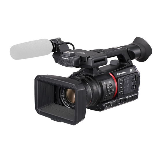
Page 21: Camera
Chapter 2 Description of Parts — Camera Camera Left side 1 Eye cup 2 Eyepiece Do not leave the eyepiece pointed toward the sun. Doing so might damage the devices inside. 3 <USB2.0 HOST> terminal Can connect to wireless LAN when the wireless module (optional) compatible to camera is mounted. 4 REC button (on the grip) Starts or stops the recording. -
Page 22: Right Side
Chapter 2 Description of Parts — Camera Right side O.I.S. FILTER FOCUS ASSIST 1/64 ZEBRA 1/16 FOCUS ∞ PUSH AUTO IRIS A. IRIS LEVEL CH 1 INPUT 1 SELECT LINE INT(L) INPUT1 +48 V INPUT2 AUDIO LEVEL INPUT 2 SELECT LINE INT(R) INPUT1... - Page 23 Chapter 2 Description of Parts — Camera 17 Rear tally lamp Illuminates when the recording is started. Flashes when the battery level becomes low. Whether or not to illuminate the lamp can be set in the menu. 18 <ND FILTER> switch Selects the ND filter to suit the illumination of the subject.
-
Page 24: Front Side
Chapter 2 Description of Parts — Camera Front side 1 Built-in microphone This is the built-in stereo microphone <L>/<R>. 2 Front tally lamp Illuminates when the recording is started. Flashes when the battery level becomes low. Whether or not to illuminate the lamp can be set in the menu. 3 Fan outlet Fan outlet for cooling fan. -
Page 25: Rear Side
Chapter 2 Description of Parts — Camera Rear side Following terminals, card slots, and card access lamps are inside each cover. f <USB3.0 DEVICE> terminal f <AV OUT> terminal f <REMOTE> terminal f <LAN> terminal f <HDMI> terminal f <DC IN 12V> terminal 1 <USB3.0 DEVICE>... -
Page 26: Top Side
Chapter 2 Description of Parts — Camera 14 <AUDIO INPUT 1> terminal (XLR, 3-pin) Connects an audio equipment or an external microphone. 15 Rear tally lamp Illuminates when the recording is started. Flashes when the battery level becomes low. Whether or not to illuminate the lamp can be set in the menu. 16 <HDMI>... - Page 27 Chapter 2 Description of Parts — Camera 12 <THUMBNAIL> button Press this button to display the thumbnail screen on the LCD monitor and viewfinder. Press it again to return to the regular display. 13 <COUNTER> button Switches the display item of the counter. 14 <RESET>...
-
Page 28: Basic Operation
Chapter 2 Description of Parts — Basic operation Basic operation Multidial operation Operate the multidial on the camera by turning it in vertical direction or pushing it. f Turning the multidial in vertical direction will move the cursor. The cursor can also be moved by pressing the <%> button, <(> button, <)> button, and <=/&> button. f Pressing the multidial will select or confirm the item with cursor. -
Page 29: Chapter 3 Preparation
Preparation Chapter 3 Before you use the camera, mount the battery following the procedures in this chapter. The mounting of accessories is also described in this chapter. -
Page 30: Power Supply
Chapter 3 Preparation — Power supply Power supply A battery or the supplied AC adaptor can be used as the power supply for the camera. f The camera is compatible to following batteries. (As of February 2019) - AG-VBR59 (supplied/optional, supports quick charging) - AG-VBR89 (optional, supports quick charging) - AG-VBR118 (optional, supports quick charging) - VW-VBD58 (optional) - Page 31 Chapter 3 Preparation — Power supply Standard charging time and recordable time Battery parts number Voltage/capacity (minimum) Charging time Continuous recordable time AG-VBR59 (supplied/optional) 7.28 V/5900 mAh Approx. 3 hours 20 minutes Approx. 3 hours 20 minutes AG-VBR89 (optional) 7.28 V/8850 mAh Approx.
-
Page 32: Attaching And Removing The Battery
Chapter 3 Preparation — Power supply Attaching and removing the battery Attaching the battery Press the battery against the battery mounting section of the camera, and mount it by sliding it downward. f Press in the battery until it clicks and gets locked. Removing the battery Lock release button Power switch... -
Page 33: Using The Ac Adaptor
Chapter 3 Preparation — Power supply Using the AC adaptor Attaching the AC adaptor Use the supplied AC adaptor. Do not use an AC adaptor for other device. The supplied AC cable is dedicated for this camera. Do not use with any other device. Also, do not use AC cable from other device on this camera. To the power outlet Fig. -
Page 34: Mounting Accessories
Chapter 3 Preparation — Mounting accessories Mounting accessories Adjusting the grip belt f Adjust the grip belt so that it fits the size of your hand. f The grip belt is already mounted to the camera. f If the buckle is difficult to tighten, move the pad forward and tighten the buckle again. Buckle Open the buckle section. -
Page 35: Mounting The Eye Cup
Chapter 3 Preparation — Mounting accessories Mounting Mounting mark Mounting mark Insert the lens hood into the camera. f Align the mounting marks on the lens hood and camera. Turn the lens hood clockwise. f Turn until the lens clicks and locks into place. Opening and closing the lens cover Use the lens cover open/close lever to open and close the lens cover. -
Page 36: Mounting The External Microphone
Chapter 3 Preparation — Mounting accessories Mounting the external microphone External microphone such as the super-directional microphone AG-MC200G (optional) can be mounted onto the handle. Screws are attached on the camera body in advance to protect the screw holes. Remove those screws when you attach the microphone holder. f The microphone holder cannot be mounted with the screws originally attached to the camera. -
Page 37: Mounting Accessories
Chapter 3 Preparation — Mounting accessories Mounting accessories You can mount and use equipment you have. Accessory mounting holes f The mounting screw size is M3. f The mounting hole depth is 6 mm. Do not over-tighten the screws when mounting accessories to the camera. –... -
Page 38: Turning On/Off The Power
Chapter 3 Preparation — Turning on/off the power Turning on/off the power Lock release button Power switch How to turn on the power Align the power switch to < j > (ON) while holding down the lock release button. The LCD monitor lights up. f The [AREA SETTINGS] screen is displayed when the power is turned on for the first time. -
Page 39: Charging The Built-In Battery
Chapter 3 Preparation — Charging the built-in battery Charging the built-in battery The date/time set in the camera is maintained by the built-in battery. The built-in battery has been exhausted if [BACKUP BATT EMPTY] is displayed in the viewfinder or LCD monitor for approximately five seconds when the power of the camera has not been turned on for a while, and then the power switch is set to <... -
Page 40: Setting The Date/Time Of The Internal Clock
Chapter 3 Preparation — Setting the date/time of the internal clock Setting the date/time of the internal clock The date/time/time zone are recorded as meta data in the clip while shooting. This will affect the management of recorded clips, so always check and set the date/time and time zone before using the camera for the first time. Do not change the setting of the date/time and time zone while shooting. -
Page 41: Preparing The Memory Card
64 GB f Operation is not guaranteed for any memory cards other than the above. f Panasonic memory cards are recommended. f The following memory cards cannot be used because they do not comply with the SD standards. - A memory card with 4 GB or more without the SDHC logo... -
Page 42: Status Of The Card Access Lamp And Memory Card
Chapter 3 Preparation — Preparing the memory card Status of the card access lamp and memory card Card access lamp Memory card status Orange (illuminated) Recording target Both loading/writing are permitted. Current recording target. Green (illuminated) Recording possible Both loading/writing are permitted. Orange (flashing) Accessing card Loading/writing are currently being performed. -
Page 43: Formatting The Memory Card
Chapter 3 Preparation — Preparing the memory card f Pull the memory card straight out when it is released from from the card slot. Close the card slot cover. Cautions when using or storing f Do not touch the connecting terminal section at the rear of the memory card. f Avoid high temperature and humidity. -
Page 44: Handling The Recording Data
Chapter 3 Preparation — Preparing the memory card r For SDXC memory card Recording capacity Recording format Recording rate 64 GB 128 GB 25 Mbps Approx. 5 hours 20 minutes Approx. 11 hours 21 Mbps Approx. 6 hours Approx. 12 hours 30 minutes 17 Mbps Approx. - Page 45 Chapter 3 Preparation — Preparing the memory card Volume label of the memory card r When the recording mode is MOV The value set in the [RECORDING] menu → [CLIP NAME] is stored in the volume label in the CAM INDEX + NEXT CARD COUNT format when the memory card is formatted.
- Page 46 Chapter 3 Preparation — Preparing the memory card f This is a sequential number assigned to each recording on the memory card. The number returns to C001 when the memory card is formatted. It will also return to C001 for the one after C999. The clip number is maintained even when the folder is split or when the clip is deleted.
-
Page 47: Setting Of Time Data
Use with this setting when using the frame rate information of the user bits with an editing device such as a computer. Use this setting to control the recording operation in TYPE1 or TYPE2 method against the Panasonic recorder (AJ-PG50, etc.). -
Page 48: Setting The Time Code
Chapter 3 Preparation — Setting of time data f Set two digits each. Press the <RESET> button to reset to [00]. Confirm the setting value of the user bits. f The setting value is confirmed when last two digits are set. Memory function of the user bits Setting contents of the user bits is automatically recorded, and it is maintained even if the power is set to <... -
Page 49: Presetting The Time Code To External
Chapter 3 Preparation — Setting of time data Time code function during battery replacement The operation of the time code generator will continue by the backup mechanism functioning even when replacing the battery. The time code of the free run may shift when any item in the [SYSTEM] menu → [FREQUENCY], [FILE FORMAT], or [REC FORMAT] is changed. Set the power to <... -
Page 50: Supplying The Time Code Externally
Chapter 3 Preparation — Setting of time data Cautions when switching the power supply from the battery to the AC adaptor while an external lock is active To maintain the continuity of the time code generator power, remove the battery only after the power status display in the camera image screen has changed to after connecting the AC adaptor to the <DC IN 12V>... -
Page 51: Assigning Function To The User Buttons
Chapter 3 Preparation — Assigning function to the USER buttons Assigning function to the USER buttons <USER 1> button <USER 2> button <USER 3> button <USER 4> button <USER 5> button <USER 6> button <USER 7> button Selected function can be assigned to the USER buttons. The USER buttons have seven USER buttons on the camera (<USER 1>... -
Page 52: Checking The Function Assigned To The User Buttons
Chapter 3 Preparation — Assigning function to the USER buttons Item Description [SPOTLIGHT] Enables/disables the auto iris control function for the spot light. [BACKLIGHT] Enables/disables the auto iris control function for the backlight compensation. [A.IRIS LEVEL] Enables/disables the auto iris level function. [IRIS] Assigns the function that switches the auto iris and manual iris. -
Page 53: Adjusting And Setting The Lcd Monitor
Chapter 3 Preparation — Adjusting and setting the LCD monitor Adjusting and setting the LCD monitor Using the LCD monitor This camera is equipped with a 3.15-inch LCD monitor. Use either the viewfinder or the LCD monitor depending on your purpose and the shooting conditions. -
Page 54: Adjusting And Setting The Viewfinder
Chapter 3 Preparation — Adjusting and setting the viewfinder Adjusting and setting the viewfinder This camera is equipped with a 0.39-inch organic EL viewfinder. Use either the viewfinder or the LCD monitor depending on your purpose and the shooting conditions. Using the viewfinder When the LCD monitor is difficult to use because the surroundings are bright, you can check the image using the viewfinder. -
Page 55: Tally Lamp
Chapter 3 Preparation — Tally lamp Tally lamp The front tally lamp and the rear tally lamp can be illuminated during the shooting. Select the [OTHERS] menu → [LED] → [TALLY LED] → [FRONT]/[REAR]/[BOTH]. f The tally lamp will flash when the camera is in the following status. ‑... -
Page 56: Chapter 4 Operation
Operation Chapter 4 This chapter describes how to operate the screen of this camera, how to operate the menu, the structure of the menu, and details of the menu. -
Page 57: Basic Operation Of The Screen
Chapter 4 Operation — Basic operation of the screen Basic operation of the screen Major button operation and screen display 1 <THUMBNAIL> button 2 <DISP/MODE CHK> button r <THUMBNAIL> button Displays the thumbnail screen. Playback, copy, delete, or protect of a clip can be performed. For details about the thumbnail screen, refer to “Thumbnail operation”... -
Page 58: Major Button Operation And Switching Screen
Chapter 4 Operation — Basic operation of the screen Major button operation and switching screen Switches the screen as follows when the <DISP/MODE CHK> button, <EXIT> button, <THUMBNAIL> button, <SET> button or <(> button is pressed. Playback screen Operation icon screen Thumbnail screen Camera image screen Mode check STATUS screen... -
Page 59: Operating Each Screen
Chapter 4 Operation — Operating each screen Operating each screen Camera image screen Displays the shooting screen. For details about the camera image screen, refer to “Screen status display” (page 155). Thumbnail screen Playback, copy, delete, or protect of a clip can be performed. For details about the thumbnail screen, refer to “Thumbnail operation”... -
Page 60: Basic Operation Of The Menu
Chapter 4 Operation — Basic operation of the menu Basic operation of the menu The setting of the camera can be changed with the menu in accordance to the shooting scene or recording contents. Set data is written and saved in the camera memory. f There are two methods of operation: a method to operate with the multidial, or a method to touch the LCD monitor. -
Page 61: Displaying The Menu
Chapter 4 Operation — Basic operation of the menu Displaying the menu Displays the menu, and select the menu or item to set. Press the <MENU> button when not recording. The menu is displayed. 1 [`]/[{] Toggles the page or changes the value when selected. These button icons are not available if they cannot be changed. -
Page 62: Operating The Menu
Chapter 4 Operation — Basic operation of the menu Operating the menu Various settings are possible from the menu. There are two methods of operation: a method to operate with the multidial, or a method to touch the LCD monitor. When operating with the multidial Operate the multidial on the camera by turning it in vertical direction or pushing it. -
Page 63: Initializing The Menu
Chapter 4 Operation — Basic operation of the menu When operating by touching the LCD monitor Operate by touching the LCD monitor. Press the <MENU> button when not recording. The menu is displayed. Select the menu to set. f Touch the menu to set. The lower level menu is displayed. f The confirmation screen is displayed depending on the menu. -
Page 64: Menu Settings
Chapter 4 Operation — Menu settings Menu settings [THUMBNAIL] menu Performs confirmation or deleting of the recording clip. This menu can be set when the thumbnail screen is displayed. [PLAYBACK] Sets the playback of recorded clips. The clip selection is generally [ALL SLOT] when toggling the thumbnail screen from the camera image screen. [CLIP SEL] Selects a clip to be displayed on the thumbnail screen. - Page 65 Chapter 4 Operation — Menu settings [MID GAIN] Sets the gain value to be assigned to the <M> position of the <GAIN> switch. The items that can be set are as follows. f [−3dB]…[18dB] (Factory setting: [6dB]) [HIGH GAIN] Sets the gain value to be assigned to the <H> position of the <GAIN> switch. The items that can be set are as follows.
- Page 66 Chapter 4 Operation — Menu settings [W.BAL PRESET] Sets the color temperature to be assigned to the <PRST> position of the <WHITE BAL> switch. The items that can be set are as follows. f [3200K], [5600K], [VAR] (Factory setting: [3200K]) [W.BAL VAR] Sets the value of [VAR] in [W.BAL PRESET].
- Page 67 Chapter 4 Operation — Menu settings [Y GET] Assigns the brightness display function. [FOCUS/IRIS] Assigns the simultaneous operation of the [FOCUS] and [IRIS]. [FOCUS/Y GET] Assigns the simultaneous operation of the [FOCUS] and [Y GET]. (Factory setting: [INHIBIT]) [IR REC] Enables/disables the IR recording.
-
Page 68: [Scene File] Menu
Chapter 4 Operation — Menu settings [AF] Sets the operation of the auto focus. [ON] Performs the operation of the auto focus when in auto mode. The <FOCUS> switch does not work. [OFF] Does not perform the operation of the auto focus when in auto mode. Performs the operation of the focus selected with the <FOCUS>... - Page 69 Chapter 4 Operation — Menu settings [FRAME RATE] Switches the shooting interval and exposure time when [VFR] is [ON]. The items that can be set are as follows. f When the [SYSTEM] menu → [FREQUENCY] → [59.94Hz] is set - [60fps], [54fps], [48fps], [44fps], [40fps], [36fps], [34fps], [32fps], [30fps], [28fps], [27fps], [26fps], [25fps], [24fps], [22fps], [21fps], [20fps], [18fps], [15fps], [12fps], [9fps], [6fps], [4fps], [2fps], [1fps] f When the [SYSTEM] menu →...
- Page 70 Chapter 4 Operation — Menu settings [DTL GAIN(+)] Sets the detail level of the plus direction (to make brighter). The items that can be set are as follows. f [−31]…[31] [DTL GAIN(−)] Sets the detail level of the minus direction (to make darker). The items that can be set are as follows.
- Page 71 Chapter 4 Operation — Menu settings [Q PHASE] Sets the phase of the area that applies the skin tone related to the Q axis. The items that can be set are as follows. f [−128]…[127] [RB GAIN CONTROL SETTING] [R GAIN AWB PRE] Sets the Rch gain when the <WHITE BAL>...
- Page 72 Chapter 4 Operation — Menu settings [G AXIS] Displays the output of G axis when the <WHITE BAL> switch is at the <A> position and automatic white balance is working, or when it is preset. In the automatic white balance operation, the color can also be changed on the G axis by changing the output of Rch and Bch. The items that can be set are as follows.
- Page 73 Chapter 4 Operation — Menu settings [G-B] Adjusts the linear matrix. (Green - Blue) The items that can be set are as follows. f [−63]…[63] [B-R] Adjusts the linear matrix. (Blue - Red) The items that can be set are as follows. f [−63]…[63] [B-G] Adjusts the linear matrix.
- Page 74 Chapter 4 Operation — Menu settings The items that can be set are as follows. f [−63]…[63] [B] ([PHASE]) Corrects the blue hue. The items that can be set are as follows. f [−63]…[63] [B-Cy] ([SAT]) Corrects the color saturation between blue and cyan. The items that can be set are as follows.
- Page 75 Chapter 4 Operation — Menu settings The items that can be set are as follows. f [−63]…[63] [Yl] ([PHASE]) Corrects the yellow hue. The items that can be set are as follows. f [−63]…[63] [Yl-Yl-R] ([SAT]) Corrects the color saturation between yellow and “colors between yellow and red”. The items that can be set are as follows.
- Page 76 Chapter 4 Operation — Menu settings [SD] Increases gain in darker areas more than HD gamma. [FILMLIKE1] Sets the characteristics that reproduce more highlight areas compared to HD gamma. [FILMLIKE2] Sets the characteristics that reproduce more highlight areas compared to [FILMLIKE1]. [FILMLIKE3] Sets the characteristics that reproduce more highlight areas compared to [FILMLIKE2].
- Page 77 Chapter 4 Operation — Menu settings [KNEE SLOPE] Sets the knee inclination. The items that can be set are as follows. f [0]…[99] [HLG KNEE SW] Enables/disables the operation of knee for HLG. The items that can be set are as follows. f [ON], [OFF] [HLG KNEE POINT] Sets the position of the knee point for HLG.
-
Page 78: [Audio] Menu
Chapter 4 Operation — Menu settings [AUDIO] menu Sets the input/output function of audio. [INPUT SETTINGS] [INPUT1 MIC LEVEL] Sets the input level of the external microphone connected to the <AUDIO INPUT 1> terminal. Enabled when the external microphone is connected and the <INPUT1>... -
Page 79: [Video Out/Lcd/Vf] Menu
Chapter 4 Operation — Menu settings (Factory setting: [OFF]) [HEAD ROOM] Sets the headroom (standard level). The items that can be set are as follows. f [12dB], [18dB], [20dB] (Factory setting: [20dB] (when [AREA SETTINGS] is [AREA 1]/[AREA 2]/[AREA 3]), [18dB] (when [AREA SETTINGS] is [AREA 4])) [OUTPUT SETTINGS] [AUDIO OUT] Sets the audio channel and the format to output from the <AV OUT>... - Page 80 Chapter 4 Operation — Menu settings (Factory setting: [1920×1080i]) NOTE t For the combinations that can be set, refer to “Format that can be output from the <SDI OUT> terminal” (page 153). [3G-SDI OUT] Sets the format of the 3G SDI signal output from the <SDI OUT> terminal. Can be set when the 3G SDI signal is output. [LEVEL‑A] Selects the LEVEL-A method.
- Page 81 Chapter 4 Operation — Menu settings [720×480p] Outputs in 720×480p. [720×576p] Outputs in 720×576p. (Factory setting: [1920×1080p]) NOTE t For the combinations that can be set, refer to “Format that can be output from the <HDMI> terminal” (page 153). [HDMI TC OUT] Sets if the time code information is output or not in the output from the <HDMI>...
- Page 82 Chapter 4 Operation — Menu settings [AV OUT ZEBRA] Sets whether to superimpose the zebra signal to the output from the <AV OUT> terminal. The settings of the zebra signal follow the settings in the [VIDEO OUT/LCD/VF] menu → [EI ASSIST] → [ZEBRA]. [ON] Superimposes.
- Page 83 Chapter 4 Operation — Menu settings [VF COLOR] Sets whether to display video in the viewfinder in color or black and white. [ON] Displays in color. [OFF] Displays in black and white. (Factory setting: [ON]) [EYE SENSOR] Sets sensitivity of the eye sensor. The items that can be set are as follows.
- Page 84 Chapter 4 Operation — Menu settings The items that can be set are as follows. f [ON], [OFF] (Factory setting: [ON]) [FRAME RATE] Displays/hides the settings in the [SCENE FILE] menu → [FRAME RATE]. The items that can be set are as follows. f [ON], [OFF] (Factory setting: [ON]) [REC REMOTE]...
- Page 85 Chapter 4 Operation — Menu settings [SHUTTER] Displays/hides the shutter speed. The items that can be set are as follows. f [ON], [OFF] (Factory setting: [ON]) [IRIS] Displays/hides F value and auto iris control status. The items that can be set are as follows. f [ON], [OFF] (Factory setting: [ON]) [ZOOM/FOCUS]...
- Page 86 Chapter 4 Operation — Menu settings [MARKER] [CENTER MARKER] Switch the type of the center marker. + (large) Open center (large) + (small) Open center (small) [OFF] Does not display. (Factory setting: [1]) [SAFETY MARKER] Selects the type of frame for the safety zone marker. Corners [OFF] Does not display.
- Page 87 Chapter 4 Operation — Menu settings [PEAKING COLOR] Sets the color of the peaking display. The items that can be set are as follows. f [RED], [GREEN], [WHITE] (Factory setting: [RED]) [BLACK & WHITE] Enables/disables the monochrome display. [ON] Enables the monochrome display. [OFF] Disables the monochrome display.
-
Page 88: [Recording] Menu
Chapter 4 Operation — Menu settings [WAVE/VECTOR] Displays the waveform and the vector. The waveform, vector or no display toggles in order each time the USER button to which [WFM] is assigned is pressed or the USER button icon is touched. (Factory setting: [WAVE]) [WFM TRANSPARENCE] Sets the transmittance of the waveform monitor. - Page 89 Chapter 4 Operation — Menu settings [ON] Performs the pre-recording. The pre-recording time is as follows. f When [REC FORMAT] is [2160-29.97p/422ALL-I 400M], [2160-25.00p/422ALL-I 400M], or [2160-23.98p/422ALL-I 400M]: Approximately 3 seconds f When [REC FORMAT] is [2160-59.94p/420LongGOP 150M], [2160-59.94p/HEVC LongGOP 200M], [2160-50.00p/420LongGOP 150M], [2160-50.00p/HEVC LongGOP 200M], [2160-29.97p/420LongGOP 100M], [2160-29.97p/HEVC LongGOP 150M], [2160-29.97p/422LongGOP 150M], [2160-25.00p/420LongGOP100M], [2160-25.00p/HEVC LongGOP 150M], [2160-25.00p/422LongGOP 150M], [2160-23.98p/420LongGOP 100M],...
-
Page 90: [Network] Menu
Chapter 4 Operation — Menu settings t The setting is fixed to [REC RUN] when the [SYSTEM] menu → [SUPER SLOW] → [ON] is set. t The setting is fixed to [FREE RUN] when the [RECORDING] menu → [PRE REC] → [ON] is set. t The setting is fixed to [FREE RUN] when the [RECORDING] menu →... - Page 91 Chapter 4 Operation — Menu settings [LAN] Connects via a wired LAN. [WLAN] Connects via a wireless LAN. [OFF] Does not connect. (Factory setting: [OFF]) [NETWORK FUNC] Selects the network function of the camera. [STREAMING] Enables the streaming function. [NDI|HX] Enables the NDI|HX function.
- Page 92 Chapter 4 Operation — Menu settings The items that can be set are as follows. f [CAMERA], [RECEIVER] (Factory setting: [RECEIVER]) [CONNECTION INFO.] Selects the internal memory of the camera or the memory card as the reference location for the transfer destination when starting a stream with the operation of the camera.
- Page 93 (Factory setting: [DIRECT]) [SSID] Enters or displays the network name of the camera (SSID). (32 characters or less) (Factory setting: [AG-CX350]) [BAND] Switches between two communication methods ([2.4GHz] or [5GHz]) when the [NETWORK] menu → [WLAN PROPERTY] → [TYPE] → [DIRECT] is selected.
- Page 94 Chapter 4 Operation — Menu settings The items that can be set are as follows. f [2.4GHz], [5GHz] (Factory setting: [2.4GHz]) [CHANNEL(2.4GHz)] Sets the channel to be used when connected to the wireless LAN with following items set. f The [NETWORK] menu → [WLAN PROPERTY] → [TYPE] → [DIRECT] f The [NETWORK] menu →...
-
Page 95: [System] Menu
(Factory setting: [DISABLE]) [EASY IP CAMERA TITLE] Configure the individual device names to display in EASY IP Setup Software. (15 characters or less) (Factory setting: [AG-CX350]) [SYSTEM] menu Configure the settings regarding the recording format of video and audio. [FREQUENCY] Sets the system frequency. -
Page 96: [Others] Menu
Chapter 4 Operation — Menu settings f When [FREQUENCY] is [59.94Hz] and [FILE FORMAT] is [AVCHD] The items that can be set are as follows. - [1080-59.94p/AVCHD PS], [1080-59.94i/AVCHD PH], [1080-59.94i/AVCHD HA], [1080-23.98p/AVCHD PH], [720-59.94p/AVCHD PM], [480-59.94i/ AVCHD SA] (Factory setting: [1080-59.94i/AVCHD PH]) [ASPECT] Sets the aspect ratio of the video to record in the SD signal format (480i and 576i). - Page 97 Chapter 4 Operation — Menu settings [COLOR BARS] [COLOR BARS TYPE] Sets the color bar to be used. [SMPTE] Uses the color bars in SMPTE standard. [FULL] Uses the full color bars. (Factory setting: [SMPTE]) NOTE t A smear may occur depending on the output resolution. [TEST TONE] Sets whether the audio test signal (tone signal with specification level 1 kHz) is output when the video is switched to the color bar.
-
Page 98: [Option] Menu
Chapter 4 Operation — Menu settings The items that can be selected are as follows. f [YES], [NO] [SERVICE MODE] Switches the camera to the service mode. You can also check software information (licenses) on a computer and other equipment. Confirm “LICENSE.TXT” for the external drive recognized by a computer. -
Page 99: Factory Setting Value Of The Scene File
Chapter 4 Operation — Factory setting value of the scene file Factory setting value of the scene file [SCENE FILE] menu The factory settings of the [SCENE FILE] menu and the items that can be selected differ depending on the [SCENE FILE] menu → [FILE SELECT] setting. - Page 100 Chapter 4 Operation — Factory setting value of the scene file [FILE SELECT] Item [F1:] [F2:FLUO.] [F3:SPARK] [F4:B.STR] [F5:CINE] [F6:HLG] [G‑R] [G‑B] [B‑R] [B‑G] [COLOR CORRECTION] [R] ([SAT]) [R] ([PHASE]) [R‑R‑Mg] ([SAT]) [R‑R‑Mg] ([PHASE]) [R‑Mg] ([SAT]) [R‑Mg] ([PHASE]) [Mg] ([SAT]) [Mg] ([PHASE]) [Mg‑B] ([SAT]) [Mg‑B] ([PHASE])
- Page 101 Chapter 4 Operation — Factory setting value of the scene file [FILE SELECT] Item [F1:] [F2:FLUO.] [F3:SPARK] [F4:B.STR] [F5:CINE] [F6:HLG] [KNEE SLOPE] [99] [99] [99] [99] [99] [99] [HLG KNEE SW] [OFF] [OFF] [OFF] [OFF] [OFF] [OFF] [HLG KNEE POINT] [55] [55] [55]...
-
Page 102: Target Items For Scene File/Setup File/Initialization
Chapter 4 Operation — Target items for scene file/setup file/initialization Target items for scene file/setup file/initialization f SCENE: Items saved in scene files. f SETUP: Items saved in setup files. f INITIALIZE: Items that are initialized with the [OTHERS] menu → [MENU INITIALIZE]. f Meaning of the symbols used in the table are as follows. -
Page 103: [Scene File] Menu
Chapter 4 Operation — Target items for scene file/setup file/initialization Item SCENE SETUP INITIALIZE [USER10 ] — [USER11] — [USER12] — [SCENE FILE] menu Item SCENE SETUP INITIALIZE [NAME EDIT] — [LOAD/SAVE/INITIALIZE] — — — [VFR] — [FRAME RATE] — [SYNC SCAN TYPE] —... - Page 104 Chapter 4 Operation — Target items for scene file/setup file/initialization Item SCENE SETUP INITIALIZE [COLOR CORRECTION] [R] ([SAT]) — [R] ([PHASE]) — [R‑R‑Mg] ([SAT]) — [R‑R‑Mg] ([PHASE]) — [R‑Mg] ([SAT]) — [R‑Mg] ([PHASE]) — [Mg] ([SAT]) — [Mg] ([PHASE]) — [Mg‑B] ([SAT]) —...
-
Page 105: [Audio] Menu
Chapter 4 Operation — Target items for scene file/setup file/initialization [AUDIO] menu Item SCENE SETUP INITIALIZE [INPUT SETTINGS] [INPUT1 MIC LEVEL] — [INPUT2 MIC LEVEL] — [INPUT1 LINE LEVEL] — [INPUT2 LINE LEVEL] — [REC CH SETTINGS] [CH1 LEVEL] — [CH2 LEVEL] —... -
Page 106: [Recording] Menu
Chapter 4 Operation — Target items for scene file/setup file/initialization Item SCENE SETUP INITIALIZE [REC MODE] — [FBC] — [HDR/DRS] — [O.I.S.] — [SCENE FILE] — [AREA] — [AUDIO LEVEL METER] — [GAIN] — [ND FILTER] — [SHUTTER] — [IRIS] —... -
Page 107: [Network] Menu
Chapter 4 Operation — Target items for scene file/setup file/initialization Item SCENE SETUP INITIALIZE [REC COUNTER] — [TIME STAMP] — [NETWORK] menu Item SCENE SETUP INITIALIZE [DEVICE SEL] — [NETWORK FUNC] — [IP REMOTE] [ENABLE/DISABLE] — [USER ACCOUNT] — — [ACCOUNT LIST] —... -
Page 108: [Others] Menu
Chapter 4 Operation — Target items for scene file/setup file/initialization Item SCENE SETUP INITIALIZE [ASPECT] — [SUPER SLOW] — [SHOOTING MODE] — [OTHERS] menu Item SCENE SETUP INITIALIZE [FILE] [SCENE FILE(SD CARD)] — — — [SETUP FILE(SD CARD)] — — —... -
Page 109: Handling Setting Data
Chapter 4 Operation — Handling setting data Handling setting data Scene files File structure of the setting data The scene files of [F1:] to [F6:] can be saved in the camera memory in accordance to the scene file number. What can be saved as a scene file is the setting contents of the [SCENE FILE] menu. In addition, the current setting values of the scene files of [F1:] to [F6:] can be saved as a file to the camera memory and the memory card, and that data can be loaded and used in the camera. -
Page 110: Setup File
Chapter 4 Operation — Handling setting data r Saving the scene file by overwriting a file on the memory card Overwrite the file selected in the list of scene files saved in the memory card in card slot 1 with the current setting values of the camera. Select the [OTHERS] menu →... - Page 111 Chapter 4 Operation — Handling setting data Enter the text to set with the keyboard. Select [Enter]. A confirmation screen is displayed. Select [SET]. The file is saved. f An error message may be displayed. For details about the error message, refer to “Cases indicated by error messages” (page 186). Saving the setup file by overwriting a file on the memory card Overwrites the file selected in the list of the setup files saved on the memory card with the current setting values of the camera.
-
Page 112: Chapter 5 Shooting
Shooting Chapter 5 This chapter describes the basic procedure for recording. This chapter also describes the special recording method. -
Page 113: Shooting
Chapter 5 Shooting — Shooting Shooting For shooting, use the following steps. 1 REC button (on the handle) 2 REC button (on the grip) 3 <AUTO/MANUAL> switch Set the video settings and the audio input. f Before shooting, the followings must be set or adjusted. ‑... - Page 114 Chapter 5 Shooting — Shooting When [FILE FORMAT] is set to [MOV] r Video Resolution [FREQUENCY] [REC FORMAT] VFR* 3840×2160 [59.94Hz] [2160-59.94p/420LongGOP 150M] 1fps to 60fps [2160-59.94p/HEVC LongGOP 200M] [2160-29.97p/420LongGOP 100M] [2160-23.98p/420LongGOP 100M] [2160-29.97p/HEVC LongGOP 150M] [2160-23.98p/HEVC LongGOP 150M] [2160-29.97p/422LongGOP 150M] 1fps to 30fps [2160-29.97p/422ALL-I 400M] [2160-23.98p/422LongGOP 150M]...
-
Page 115: Adjustable Settings When Shooting
Chapter 5 Shooting — Adjustable settings when shooting Adjustable settings when shooting Adjust the iris and gain when shooting. Iris Switch to manual mode with the <AUTO/MANUAL> switch. (page 113) Press the <IRIS> button to switch the adjustment method for the lens aperture. Auto iris: Adjusts the iris setting automatically. -
Page 116: Area Mode Function
Chapter 5 Shooting — Adjustable settings when shooting Auto focusing Performs automatic focusing while the <PUSH AUTO> button is pressed during manual focus mode. Manual focus assist mode You can switch from the manual focus mode to the manual focus assist mode by setting the [CAMERA] menu → [SW MODE] → [MF ASSIST] → [ON]. f Compared to the manual focus mode, you can adjust the focus (course adjustment) by rotating the focus ring approximately a half-turn. -
Page 117: Adjusting The White And Black Balance
Chapter 5 Shooting — Adjusting the white and black balance Adjusting the white and black balance To obtain high-quality video at all times using the camera, the white and black balance must be adjusted according to conditions. Adjust the AWB (white balance adjustment), ABB (black balance adjustment), and AWB (white balance adjustment) in order to obtain higher image quality. -
Page 118: Black Balance Adjustment
Chapter 5 Shooting — Adjusting the white and black balance When the white balance has not been automatically adjusted When the white balance has not been successfully adjusted, an error message is displayed on the viewfinder screen and LCD monitor displays. Error message Meaning Remedy... - Page 119 Chapter 5 Shooting — Adjusting the white and black balance t The gain switching circuit is automatically switched during black balance adjustment. Flicker or noise sometimes appears on the viewfinder screen and LCD monitor. This is not a malfunction. Black balance memory Values stored to memory are saved even if the camera is turned off.
-
Page 120: Using The Zoom Function
Chapter 5 Shooting — Using the zoom function Using the zoom function Adjust the angle of view you want to shoot. The camera has a 20x optical zoom. This can be expanded up to approximately 32 times (approximately 24 times in UHD recording) when the [CAMERA] menu → [SW MODE] → [i.ZOOM] →... -
Page 121: Image Quality Adjustment
Chapter 5 Shooting — Image quality adjustment Image quality adjustment The image quality of the video to record can be set in the [SCENE FILE] menu. Measurement equipment such as a vector scope is necessary to change “Advanced settings”. Detail function This function thickens or weakens the outlines of images. -
Page 122: Chroma Setting Function
Chapter 5 Shooting — Image quality adjustment r General settings Use the camera with the factory settings. r Advanced settings Set with the [SCENE FILE] menu → [RB GAIN CONTROL SETTING]. f When the <WHITE BAL> switch is at the <PRST> position [R GAIN AWB PRE]: Sets to add or reduce the intensity of the red color. -
Page 123: Color Correction Function
Chapter 5 Shooting — Image quality adjustment It performs fine adjustment relatively on the matrix table selected in [MATRIX]. Since the fine adjustment is performed relatively, if the matrix table selected in [MATRIX] differs, the color representation may differ even when the same value is set. -
Page 124: Knee Function
Chapter 5 Shooting — Image quality adjustment Knee function This function sets the compression of video signals to prevent halation in images. r General settings Use the camera with the factory settings. r Advanced settings Set with the [SCENE FILE] menu → [KNEE SETTING]. [KNEE MODE]: Sets the operation mode of knee function ([AUTO]/[MANUAL]/[OFF]). -
Page 125: Variable Frame Rate (Vfr) Recording Function/Super Slow Recording Function
Chapter 5 Shooting — Variable frame rate (VFR) recording function/super slow recording function Variable frame rate (VFR) recording function/super slow recording function It is possible to acquire smooth slow motion or quick motion vide by shooting with a different frame rate from the frame rate to play back. Variable frame rate (VFR) Allows the high-speed shooting from 1fps to maximum of 60fps. -
Page 126: Audio Input
Chapter 5 Shooting — Audio input Audio input The camera can record two channels of audio. The audio to input to each channel can be switched to the built-in microphone, an external microphone, or a connected audio device. Switching the audio input r Audio recording format The audio recording format such as compression format varies depending on the recording mode. -
Page 127: Monitoring The Audio
Select the [AUDIO] menu → [REC CH SETTINGS] → [HEAD ROOM] → [12dB]/[18dB]/[20dB]. [20dB]: Select this when matching the recording standard level with the Panasonic broadcasting AJ series camera. [12dB]: Select this when matching the recording standard level with the Panasonic professional AG-UX series camera. -
Page 128: Special Recording Function
Chapter 5 Shooting — Special recording function Special recording function Special recording such as pre-recording or relay recording is possible by setting the menu. Pre-recording Records the video and audio from specific time before the operation to start the recording. Operation to start recording Operation to stop recording (Time) -
Page 129: Simultaneous Recording
Chapter 5 Shooting — Special recording function t The recording target cannot be switched when the remaining recording capacity of the relay memory card is less than one minute. t The maximum continuous recording time for relay recording is ten hours. t The recording is stopped once when the recording time of relay recording exceeds ten hours. - Page 130 Chapter 5 Shooting — Special recording function Memory card recording time REC button operations Button operation for background recording stop* No remaining space on card slot 1 REC PAUSE REC STOP Card slot 1 (Main recording) A clip Stand-by B clip REC PAUSE Card slot 2 A clip...
-
Page 131: Interval Recording
Chapter 5 Shooting — Special recording function Interval recording The camera will record one frame at each set time interval. 1 frame recording 1 frame recording 1 frame recording (Time) Time set in [INTERVAL TIME] Time set in [INTERVAL TIME] Select the [RECORDING] menu →... -
Page 132: Convenient Shooting Functions
Chapter 5 Shooting — Convenient shooting functions Convenient shooting functions Zebra patterns display The camera can display two types of zebra patterns to the output image from the LCD monitor. Select the [VIDEO OUT/LCD/VF] menu → [EI ASSIST] → [ZEBRA] → [ON]. f Select [MOMENT]. -
Page 133: Displaying The Safety Zone Marker
Chapter 5 Shooting — Convenient shooting functions Displaying the safety zone marker A safety zone marker can be displayed. Select the type of the frame in the [VIDEO OUT/LCD/VF] menu → [MARKER] → [SAFETY MARKER]. f The safety zone marker is not displayed when [OFF] is selected. Setting the size of the frame. - Page 134 Chapter 5 Shooting — Convenient shooting functions Setting the enlargement rate Select the enlargement rate in the [VIDEO OUT/LCD/VF] menu → [FOCUS ASSIST] → [EXPAND VALUE]. f The enlargement rate can be selected from [×2], [×3], or [×4]. Setting the enlargement position The enlargement position can be selected from nine positions when the enlarged display function is enabled.
-
Page 135: Optical Image Stabilizer Function
Chapter 5 Shooting — Convenient shooting functions Monochrome display Select the [VIDEO OUT/LCD/VF] menu → [FOCUS ASSIST] → [BLACK & WHITE] → [ON]. NOTE t The monochrome display can be enabled while the peaking display is functioning. Select the [VIDEO OUT/LCD/VF] menu → [FOCUS ASSIST] → [BLACK & WHITE] → [DURING PEAKING]. Highlighting the outlines of images It is easier to focus if the contours of images on the LCD monitor and viewfinder are highlighted. -
Page 136: Waveform Monitor Function
Chapter 5 Shooting — Convenient shooting functions NOTE t The order to display the year, month, and day of the time stamp follows the settings in the [OTHERS] menu → [CLOCK] → [DATE FORMAT]. t The display of the month for the time stamp to record on the image is in English. t The size of the characters and the display position of the time stamp varies depending on the recording format. -
Page 137: Level Gauge
Chapter 5 Shooting — Convenient shooting functions NOTE t The image quality decreases the higher the enlargement ratio when using the digital zoom. t The digital zoom is cancelled when the power is turned off. Level gauge A level gauge that indicates the horizontal and vertical inclinations of the camera can be displayed on the LCD monitor. The line of the level gauge is displayed in orange while the camera is inclined. -
Page 138: Operation Icon Screen Display
Chapter 5 Shooting — Operation icon screen display Operation icon screen display You can select the scene file or execute the functions assigned to [USER8] through [USER12]. Displaying the operation icon screen Press the multidial or the <SET> button while [ ICONS] is displayed in the LCD monitor, or touch the LCD monitor for one second or longer while the camera image screen is displayed. -
Page 139: Multi Manual Function
Chapter 5 Shooting — Multi manual function Multi manual function Operate the multidial to change settings and perform other operations without displaying the menu. Operations can also be performed by pressing the <=/&> button, <(> button, <SET> button, and <EXIT> button. You can execute the following functions. -
Page 140: Setting The Frame Rate Of The Variable Frame Rate Recording Function
Chapter 5 Shooting — Multi manual function Press the multidial. SYNCHRO] is displayed. Turn the multidial to select the synchro scan shutter speed. Press the multidial. The setting changes to the value displayed and ends. Press the <EXIT> button to exit without changing the setting. Setting the frame rate of the variable frame rate recording function Turn the multidial to display the [ FRAME RATE]. -
Page 141: Chapter 6 Playback
Playback Chapter 6 Data including additional information such as image, audio, and meta data that are recorded by single shooting is saved as a clip. Playback, copy, etc., of the clip can be performed on the camera. -
Page 142: Thumbnail Operation
Chapter 6 Playback — Thumbnail operation Thumbnail operation Thumbnail operation overview A clip is a group of data recorded by a single shooting, which includes additional information such as image, audio, and meta data. The following operations can be performed while viewing the clip thumbnails displayed on the LCD monitor. f Playback, delete, protect, and copy of a clip (only possible for a clip recorded in AVCHD) The two methods of operation are the method to operate with the multidial or the <%>... - Page 143 Chapter 6 Playback — Thumbnail operation 8 Clip that cannot be played back Displays when the clip cannot be played back in the camera such as standard violation. 9 Page switching button Switches the page of the thumbnail screen. [`]: Moves to previous page [{]: Moves to next page 10 Scroll bar Indicates which part of the whole thumbnail is currently being viewed.
- Page 144 Chapter 6 Playback — Thumbnail operation r Clip information 1 Clip that cannot be played back This is displayed when the clip cannot be played back with the camera because the system frequency is different, etc. 2 Thumbnail number 3 Protection status of the clip This is displayed when the clip is protected.
-
Page 145: Copying Clips
Chapter 6 Playback — Thumbnail operation Copying clips Clips can be copied between memory cards. Only the clip recorded in AVCHD can be copied. Fig. 1 Fig. 2 Fig. 3 Fig. 4 Fig. 5 Press the <THUMBNAIL> button. The thumbnail screen is displayed. Press the <MENU>... -
Page 146: Deleting Clips
Chapter 6 Playback — Thumbnail operation NOTE t The clip whose recording file format is MOV cannot be copied. t The copy is not possible when the volume of the selected clip is larger than the available card capacity of the destination. t It cannot copy when the copy destination card is write protected. -
Page 147: Restoring Clips
Chapter 6 Playback — Thumbnail operation Press the <MENU> button while the thumbnail screen is displayed. The menu is displayed. Select the [THUMBNAIL] menu → [CLIP] → [PROTECT]. Select [SELECT]. The thumbnail screen is displayed. Select the clip to protect in the thumbnail screen. is displayed on the selected clip. -
Page 148: Playing Back Clips
Chapter 6 Playback — Thumbnail operation Playing back clips In the [SYSTEM] menu → [FREQUENCY], select the system frequency to play back. In the [SYSTEM] menu → [FILE FORMAT], select the file format (MOV or AVCHD) to play back. In the [SYSTEM] menu → [REC FORMAT], select the signal format and codec mode to play back. Press the <THUMBNAIL>... - Page 149 Chapter 6 Playback — Thumbnail operation Playback operation Operating procedure Skip playback Touch the LCD monitor while playing back, and slide from right to left (left to right). (cue up of the clip) When sliding from left to right, the clip skips to the beginning of the previous clip if the current playback position of the clip is at less than three seconds from the beginning.
-
Page 150: Useful Playback Function
Chapter 6 Playback — Useful playback function Useful playback function Resume play When the playback of a clip is stopped midway, it will start the playback from the position that stopped the playback when it is played back the next time. Select the [THUMBNAIL] menu →... -
Page 151: Still Image Recording Function
Chapter 6 Playback — Still image recording function Still image recording function One frame of the recorded video can be recorded as a still image. Number of pixels of the still image to be recorded is same as the number of pixels of the recorded video. Select by touching or pressing the multidial at the scene to be recorded as a still image while playing back. -
Page 152: Chapter 7 Output And Screen Display
Output and Screen Display Chapter 7 This chapter describes the screen displayed on the output video and LCD monitor. -
Page 153: Output Format
Chapter 7 Output and Screen Display — Output format Output format The format to be output differs depending on the setting in the [SYSTEM] menu → [FREQUENCY]/[REC FORMAT]. Format that can be output from the <SDI OUT> terminal The format that can be output from the <SDI OUT> terminal differs with following combination of the settings. f [SYSTEM] menu →... - Page 154 Chapter 7 Output and Screen Display — Output format Item Output format [REC FORMAT] [OUT FORMAT] [FREQUENCY] Resolution Frequency 59.94i 1920×1080 59.94i 29.97p 1920×1080 29.97p 23.98p 1920×1080 23.98p 59.94p 1280×720 1280×720 59.94p 59.94i 720×480 720×480 59.94p [50.00Hz] 50.00p 3840×2160 3840×2160 50.00p 3840×2160 50.00p (4:2:0/8-bit) 1920×1080 50.00p (Factory setting) 1920×1080 50.00i...
-
Page 155: Screen Status Display
Chapter 7 Output and Screen Display — Screen status display Screen status display Screen display during shooting 9 10 11 12 13 14 15 16 999min 999min RELAY TCG 1 2 : 3 4 : 5 6 : 2 8 S.SLOW120 2160-59.94p INTRVL... - Page 156 Chapter 7 Output and Screen Display — Screen status display f (No display): It is in one of the following conditions. - A memory card has not been inserted. - The memory card cannot be recognized. - The [NETWORK] menu → [NETWORK FUNC] → [NDI|HX] is set. 7 External equipment recording operation control status (<SDI OUT>/<HDMI>...
- Page 157 Chapter 7 Output and Screen Display — Screen status display : When set to the wireless LAN and the wireless LAN is not operating properly : When set to the wired LAN and the ROP is not connected : When set to the wired LAN and the ROP is connected : When set to the wired LAN and the wired LAN is not operating properly f (No display): When both the wireless LAN and the wired LAN are disabled 16 Power status...
- Page 158 Chapter 7 Output and Screen Display — Screen status display f [2160-29.97p] f [2160-25.00p] f [2160-23.98p] f [1080-59.94p] f [1080-50.00p] f [1080-29.97p] f [1080-25.00p] f [1080-23.98p] f [1080-59.94i] f [1080-50.00i] f [720-59.94p] f [720-50.00p] f [480-59.94i] f [576-50.00i] 28 Recording format Displays the file format and the recording codec set in the [SYSTEM] menu →...
-
Page 159: Screen Display During Playback
Chapter 7 Output and Screen Display — Screen status display 42 Digital zoom Displays the digital zoom ratio. f [D2×]: Two times f [D5×]: Five times f [D10×]: Ten times 43 Focus Displays the focus value. The display of the focus value follows the setting in the [VIDEO OUT/LCD/VF] menu → [INDICATOR] → [ZOOM/FOCUS]. Displays in the position value from [00] to [99] when set to [NUMBER]. -
Page 160: Checking And Displaying Shooting Status
Chapter 7 Output and Screen Display — Screen status display Checking and displaying shooting status The screen to check the setting and status of the camera can be displayed. Press the <DISP/MODE CHK> button while the camera image screen is displayed to hide most of the items. Press the <DISP/MODE CHK>... -
Page 161: Mode Check Display
Chapter 7 Output and Screen Display — Screen status display Displays when the remaining recording capacity of the memory card or remaining battery level gets low. Displays when the multidial, <=/&> button, <(> button, or <SET> button is pressed. The display is cleared approximately three seconds after the operation. Mode check display The camera settings and status can be displayed on the viewfinder or LCD monitor screen for check. - Page 162 Chapter 7 Output and Screen Display — Screen status display AUDIO screen Displays the audio input/output settings and the audio level meter. Item Description [AUDIO] [AUDIO OUT] Displays the audio channel and the format output from the <AV OUT> terminal, headphones terminal, and the built-in speaker with [CH1]/[CH2]/[CH1/2 STEREO]/[CH1/2 MIX].
-
Page 163: Chapter 8 Connecting To External Devices
Connecting to External Devices Chapter 8 This chapter describes the external devices that can be connected to the camera. -
Page 164: Connecting With Headphones And Tv/Monitor
Chapter 8 Connecting to External Devices — Connecting with headphones and TV/monitor Connecting with headphones and TV/monitor Headphones Headphones (optional) can be connected to the headphone terminal (3.5 mm stereo mini jack). Headphone terminal NOTE t Audio is not output from the built-in speaker when headphones are connected to the headphone terminal. Remote control Connect the remote control unit (optional) to the <REMOTE>... -
Page 165: Tv/Monitor
For the BNC cable (optional) connected to the <SDI OUT> terminal, prepare a double-shielded cable equivalent to 5C-FB. t Use the double shielded cable supporting 4K/60P as the HDMI cable (optional). Also, it is recommended to use the Panasonic HDMI cable compatible to 4K/60P as the HDMI cable. -
Page 166: Connection Function Via The
Chapter 8 Connecting to External Devices — Connection function via the <USB3.0 DEVICE>/<USB2.0 HOST> terminal Connection function via the <USB3.0 DEVICE>/<USB2.0 HOST> terminal Connection with a computer in card reader mode Connect the camera to a computer via the USB type C cable to use the camera as a card reader for the memory card. Connecting to a computer USB type C cable (optional) Type C.../ -
Page 167: Remote Operation By Ipad Or Android Terminal
Chapter 8 Connecting to External Devices — Remote operation by iPad or Android terminal Remote operation by iPad or Android terminal The camera can be connected to the wireless LAN by connecting a wireless module (optional) compatible to the camera to the <USB2.0 HOST> terminal of camera. -
Page 168: Chapter 9 Network Connection
Network Connection Chapter 9 This chapter describes how to use the camera by connecting to a network. -
Page 169: Network Connection
The camera can be connected to a network via a wireless LAN or wired LAN. For details on wireless modules that can be connected, refer to the support desk at the following website: https://pro-av.panasonic.net/ Attach the wireless module (optional) to the <USB2.0 HOST> terminal to use a wireless LAN. -
Page 170: Preparing For Connection
Chapter 9 Network Connection — Preparing for connection Preparing for connection For the wireless module Mount the wireless module (optional) to the camera. <USB2.0 HOST> terminal Fig. 1 Fig. 2 Open the <USB2.0 HOST> terminal cover on the top-back side. (Fig. 1) Connect the wireless module to the <USB2.0 HOST>... -
Page 171: Network Settings
Select the SSID of the camera from the SSID list in the iPad/Android terminal, and enter the password (encryption key). Display the wireless access point list screen in wireless LAN setting, and select SSID of the camera. f Factory setting: [AG-CX350] When the password confirmation screen appears, enter the password (encryption key). -
Page 172: Wired Lan Settings
Chapter 9 Network Connection — Network settings Select the SSID of the searched wireless access point. Setting is completed when the [ENCRYPT KEY] (encryption key, password) is not set. If the [ENCRYPT KEY] is set, enter the password, and select [Enter]. Close the menu or return to the level of the [NETWORK] menu. -
Page 173: Specifying The Network Settings Using The Settings Tool
Enter the name (nickname) of the camera. Entered name will be the name to be displayed on the EASY IP Setup Software screen. Installing software Download and install EASY IP Setup Software (EasyIPSetup.exe) from the following website. (Windows) https://pro-av.panasonic.net/ – 173 –... - Page 174 Chapter 9 Network Connection — Network settings r EASY IP Setup Software (EasyIPSetup.exe) Configure the network settings of the camera. Performing settings of the camera using EASY IP Setup Software The settings for the camera network can be performed using EASY IP Setup Software. The settings for multiple cameras need to be performed on each camera.
-
Page 175: Confirming The Network Status
Chapter 9 Network Connection — Network settings Confirming the network status The status of the camera network can be checked using the following operations. Select the [NETWORK] menu → [INFORMATION] → [STATUS]. – 175 –... -
Page 176: Connecting To The Ipad Or Android Terminal
Chapter 9 Network Connection — Connecting to the iPad or Android terminal Connecting to the iPad or Android terminal The camera can be operated from the iPad or Android terminal. Mounting the wireless module Mount the wireless module (optional) to the camera. (page 170) Camera settings Specifying the network settings Specify the network settings. -
Page 177: Connecting To The Cx Rop Application
Chapter 9 Network Connection — Connecting to the iPad or Android terminal r For Android terminal f Download the CX ROP app from the Google Play Store. NOTE t For information such as the supported OS of the CX ROP app, refer to the App Store or the Google Play Store download page. Connecting to the CX ROP application Connect to the camera following the CX ROP app guide. -
Page 178: Streaming Function
Chapter 9 Network Connection — Streaming function Streaming function You can perform streaming of audio and video currently shot with the camera over a network (wired LAN/wireless LAN). Streaming can be performed using the camera, an application software of a device connected via a network, or a server that is capable of receiving streaming video sent from the camera. -
Page 179: Starting Streaming With An Operation From The Application Software
Chapter 9 Network Connection — Streaming function [SYSTEM] menu [NETWORK] menu → [STREAMING] [FREQUENCY] [REC FORMAT] [STREAMING FORMAT] [1080-25.00p/422LongGOP 50M] [1920×1080-25fps 14M] [1080-25.00p/422ALL-I 100M] [1920×1080-25fps 6M] [1080-50.00i/422LongGOP 50M] [1920×1080-25fps 1M] [1080-50.00i/422ALL-I 100M] [1280×720-25fps 8M] [1280×720-25fps 2M] [1280×720-25fps 1M] [640×360-25fps 4M] [640×360-25fps 1.5M] [640×360-25fps 0.7M] (Factory setting) [320×180-25fps 4M]... - Page 180 Chapter 9 Network Connection — Streaming function Select [YES] when the confirmation message is displayed. NOTE t The name of the file in the memory card to save the destination information cannot be changed. t The file with the destination information saved on the memory card is encrypted. r Loading destination information from the memory card Insert the memory card with the destination information saved into card slot 1.
-
Page 181: Ndi|Hx Function
Chapter 9 Network Connection — NDI|HX function NDI|HX function The camera can be connected to a NDI|HX compatible switches made by NewTek. NOTE t For details of each operation, refer to the operating instruction of the NDI|HX compatible switcher. t The following functions cannot be used when the NDI|HX function is enabled. Some of the menu items related to those functions cannot be selected as well. - Page 182 Chapter 9 Network Connection — NDI|HX function Using the NDI|HX function Control the camera by operating the NDI|HX compatible switcher. NOTE t Streaming may stop when the date/time is set while streaming. Disabling the NDI|HX function Select the [NETWORK] menu → [NDI|HX] → [CLEAR ACTIVATION]. The activation information saved to the camera is deleted.
-
Page 183: Chapter 10 Notes
Notes Chapter 10 Maintenance of the camera or frequently asked questions are described. -
Page 184: Frequently Asked Questions
Can the battery that was used in the previous models used? f VW-VBD58 (optional) can be used. It is recommended to use the following Panasonic genuine batteries. - AG-VBR59 (supplied/optional, 7.28 V, 5900 mAh) - AG-VBR89 (optional, 7.28 V, 8850 mAh) - AG-VBR118 (optional, 7.28 V, 11800 mAh) -
Page 185: Playback
Chapter 10 Notes — Frequently asked questions - When the super slow recording function is enabled - When the interval recording function is enabled is displayed in the camera image screen when audio cannot be recorded. Playback r The clip cannot be played back. f The clip displaying in the thumbnail screen cannot be played back. -
Page 186: Warning System
Chapter 10 Notes — Warning system Warning system When an error is detected right after the camera is turned on or during the operation, the occurrence of the error is notified in the camera image screen of the LCD monitor or by the tally lamp. Deal with the error by following the indications. Cases indicated by error messages System error Screen display... - Page 187 Chapter 10 Notes — Warning system Alert Screen display Description Behavior and cause Camera image screen [SIMUL REC WARNING <SLOT 1>]/ An error has occurred in one of the memory cards during A message is displayed for approximately five seconds. [SIMUL REC WARNING <SLOT 2>] simultaneous recording.
- Page 188 Chapter 10 Notes — Warning system Message Screen display Description Behavior and cause Camera image screen [CANNOT PLAY.] This is a clip that cannot be played back. A message is displayed. (When it cannot be played back due to difference of the f Confirm if the system frequency of the clip is the same as system frequency, etc.) the system frequency of the camera.
- Page 189 Chapter 10 Notes — Warning system Screen display Description Behavior and cause Camera image screen [Cannot record - Playlist capacity is The camera tried to record on a memory card where A message is displayed. full.] the number of playlists for recording has reached the f Replace the memory card or delete unnecessary clips.
-
Page 190: Recording Function That Cannot Be Used Simultaneously
Chapter 10 Notes — Recording function that cannot be used simultaneously Recording function that cannot be used simultaneously Depending on the recording function that is set, there are recording functions that cannot be used simultaneously. f Meaning of the symbols used in the table are as follows. - l: Can be used simultaneously. -
Page 191: Updating The Camera Firmware
Update is completed by loading the downloaded file to the camera via the memory card. Insert the memory card that stores the update file into card slot 1, and select the [OTHERS] menu → [INFORMATION] → [UPDATE]. For update method, refer to the support desk at the following website: https://pro-av.panasonic.net/ t When updating the firmware, use the AC adaptor or sufficiently charged battery. -
Page 192: Cleaning And Storing
Chapter 10 Notes — Cleaning and storing Cleaning and storing Cleaning the camera body f Remove the battery or disconnect the AC cable from the power outlet before cleaning. f Do not use benzine or thinner to clean the camera. Using benzine or thinner may cause deformation or peeling off of the paint of the camera body. f Wipe the camera body with a soft and clean cloth. - Page 193 Specification Chapter 11 This chapter describes the specifications of this product.
-
Page 194: Dimensions
Chapter 11 Specification — Dimensions Dimensions 180 mm (7-3/32 inches) 311 mm (12-1/4 inches) 393 mm (15-15/32 inches) – 194 –... -
Page 195: General
Chapter 11 Specification — Specifications Specifications General Power DC e 7.28 V (when battery is used) DC e 12 V (when the AC adaptor is used) Power consumption 17 W (when the LCD monitor is used) indicates safety information. Operating ambient temperature 0 °C –... -
Page 196: Memory Card Recorder
Chapter 11 Specification — Specifications Synchro scan shutter speed When the [SYSTEM] menu → [FREQUENCY] → [59.94Hz] is set f 59.94i/59.94p mode: 1/60.0 sec. – 1/7200 sec. f 29.97p mode 1/30.0 sec. – 1/7200 sec. f 23.98p mode 1/24.0 sec. – 1/7200 sec. When the [SYSTEM] menu →... -
Page 197: Digital Audio
Chapter 11 Specification — Specifications Video compression format H.264/MPEG-4 AVC High Profile H.265/MPEG-H HEVC Main10 Profile Digital audio Recording audio signal f MOV: 48 kHz/24-bit, 2ch f AVCHD: 48 kHz/16-bit, 2ch Audio recording format f MOV: LPCM f AVCHD: Dolby Audio Headroom 12 dB/18 dB/20 dB switchable menu Streaming... -
Page 198: Monitor
Chapter 11 Specification — Specifications <USB3.0 DEVICE> terminal USB 3.1 GEN1 type C connector, with USB mass storage function, without USB bus-powered function <LAN> terminal RJ-45: 1000BASE-T/100BASE-TX/10BASE-T <DC IN 12V> terminal DC12 V, EIAJ type 4 Monitor LCD monitor 3.2-inch TFT LCD (3:2): Approx. 1620000 dots, touch panel compatible Video display area (16:9): Approx. -
Page 199: Index
Index Index AC adaptor Knee function Attaching Accessory LCD monitor Mounting Status display Area mode function Lens cover Lens hood Audio input Level gauge Audio device Built-in microphone Confirming setting Macro External microphone Manual focus Level adjustment Matrix function Monitor Memory card Switching Data structure... - Page 200 Index Shoulder strap Simultaneous recording Skin tone function Specifications Still image recording function Streaming function Super gain Super slow Switching screen Tally lamp Thumbnail Thumbnail screen Time code External preset Supplying to external Time data Time stamp function Tripod Update Usage restriction User bits USER buttons...
- Page 201 Web Site: http://www.panasonic.com © Panasonic Corporation 2019...