Table of Contents
Advertisement
SPECIFICATIONS ........................................................................................................................................... 2
EXTERNAL DIMENSIONS ............................................................................................................................... 3
WIRING DIAGRAMS ....................................................................................................................................... 4
ELECTRICAL PARTS ...................................................................................................................................... 5
MICROCOMPUTER CONTROL SYSTEM ...................................................................................................... 8
FUNCTIONS ................................................................................................................................................... 9
TROUBLESHOOTING OF THE CONTROL CIRCUIT .................................................................................. 17
REFRIGERATION CYCLE ........................................................................................................................... 21
PERFORMANCE CURVES .......................................................................................................................... 23
REFRIGERANT PIPE AINSTALLATION WORKS ......................................................................................... 24
DISASSEMBLING PROCEDURE ................................................................................................................. 25
REPLACEMENT PARTS LIST ....................................................................................................................... 29
SERVICE MANUAL
ROOM AIR CONDITIONERS
MODELS
In the interests of user-safety (Required by safety regulations in some
countries) the set should be restored to its original condition and only
parts identical to those specified should be used.
TABLE OF CONTENTS
SHARP CORPORATION
1
SPLIT SYSTEM
INDOOR UNIT
AY-A079E
AY-A099E
OUTDOOR UNIT
AE-A079E
AE-A099E
AY/AE-A079E
AY/AE-A099E
S2915AYA099E/
Page
Advertisement
Table of Contents

Related Manuals for Sharp AY-A079E


Summary of Contents for Sharp AY-A079E
-
Page 1: Table Of Contents
AY/AE-A079E AY/AE-A099E SERVICE MANUAL S2915AYA099E/ SPLIT SYSTEM ROOM AIR CONDITIONERS INDOOR UNIT AY-A079E MODELS AY-A099E OUTDOOR UNIT AE-A079E AE-A099E In the interests of user-safety (Required by safety regulations in some countries) the set should be restored to its original condition and only parts identical to those specified should be used. -
Page 2: Specifications
AY/AE-A079E AY/AE-A099E SPECIFICATIONS ITEMS INDOOR UNIT OUTDOOR UNIT INDOOR UNIT OUTDOOR UNIT AY-A079E AE-A079E AY-A099E AE-A099E Cooling capacity Heatpump Heating capacity Moisture removal Liters/h Electrical data Phase – Single Rated frequency Rated voltage range 198 to 264 Rated voltage 220 - 240... -
Page 3: External Dimensions
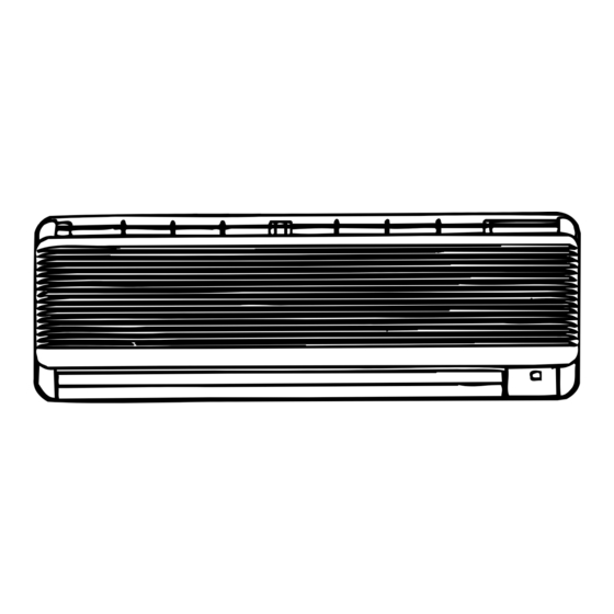
AY/AE-A079E AY/AE-A099E EXTERNAL DIMENSIONS 19.5 Length unit (mm) Remote control Figure E-1. INDOOR UNIT for AY-A079E and AY-A099E 20˚ Figure E-2. OUTDOOR UNIT for AE-A079E and AE-E099E... -
Page 4: Wiring Diagrams
: PURPLE G(Y) : GREEN–YELLOW Figure W-1. Wiring Diagram for AY-A079E and AY-A099E I N D O O R U N I T O U T D O O R U N I T T E R M I N A L B O A R D 2... -
Page 5: Electrical Parts
: G R E E N - Y E L L O W G ( Y ) : R E D : W H I T E Figure W-3. Wiring Diagram for AE-A099E ELECTRICAL PARTS For Model AY-A079E and AE-A079E DESCRIPTION MODEL REMARKS SITE Compressor... - Page 6 AY/AE-A079E AY/AE-A099E...
- Page 7 AY/AE-A079E AY/AE-A099E JP33 JP50 DEICE A DEICE B OFF WIDEH PREHEAT JP10 12H / 24H JP46 JP51 JP14 DE.FAN B JP42 JP13 DE.FAN A JP12 FREEZE B JP39 POWER ON JP11 JP38 FREEZE A BCN2 JP35 QPWBFB252JBE0(C) JP 27 DPWBFA JBK0(C) Figure L-2.
-
Page 8: Microcomputer Control System
AY/AE-A079E AY/AE-A099E Microcomputer (IC1) The microcomputer is a CMOS, one chip, 8-bit microcomputer. Microcomputer port allocation is as follows. Pin Terminal Input Pin Terminal Input No. Name Output Function No. Name Output Function MODEL B 33 P27 MODEL 4 FAN H 34 P26 MODEL 3 FAN M... -
Page 9: Functions
AY/AE-A079E AY/AE-A099E FUNCTIONS 1. Temperature control characteristic HEAT operation COOL operation In the “HEAT” mode, the thermostat circuit In the “COOL” mode, the thermostat circuit is is controlled by six thermostat lines (H01 thru controlled by four thermostat lines (C1 thru C4). H4). - Page 10 AY/AE-A079E AY/AE-A099E DRY operation Heat operation On the switch on, the compressor always starts The compressor turns on or off, at State 2 , turns to operate for 2 minutes with fan speed “D” on continuously at State 1 & 3 . (slower than “UL”).
- Page 11 30sec. 30sec. MODELS Line 10sec. 10sec. Thermo off time 53˚C 53˚C 53˚C Notes: Compressor is off when compressor OFF time is 15 minutes. AY-A079E 49˚C 49˚C 49˚C Figure Y-7 53˚C 54˚C 54˚C AY-A099E 5. Preheat air flow 49˚C 50˚C 50˚C...
- Page 12 AY/AE-A079E AY/AE-A099E 7. Current control Switch ON Defrost Defrost This system, in order to prevent overcurrent during heating operation, controls the outdoor fan motor and changes the indoor fan motor speed by detecting total current. When the current exceeds P2, the outdoor fan motor is Heating Heating Heating...
- Page 13 AY/AE-A079E AY/AE-A099E 13. Automatic air conditioning 15. Outputs in each operation mode When automatic air conditioning is selected, the operation mode and preset temperature are set Table Y-5 automatically according to the room temperature on Outdoor Indoor Valve starting operation. Mode Compressor Fan Motor...
- Page 14 AY/AE-A079E AY/AE-A099E 19.Diagnosis procedure When indoor fan motor is out of order or compressor lock occurs, the compressor, inddor fan motor, outdoor fan motor, and louver are all stopped and the operation LED(red) turns on or off syncronously with the timimg of the timer LED.
- Page 15 AY/AE-A079E AY/AE-A099E Table Y-6 [AY-A079E] Lamps Louver Indoor Step Output for outdoor unit Fan motor YELLOW OPEN Compressor Flickering Reverse Valve Outdoor Fan Motor CLOSE (Back to step 1) : 7˚C Room temp. 42˚C : 7˚C (Room temp.) or (Room temp.) 42˚C...
- Page 16 AY/AE-A079E AY/AE-A099E Table Y-7[AY-A099E] Lamps Louver Indoor Step Output for outdoor unit Fan motor YELLOW OPEN Compressor Flickering Reverse Valve Outdoor Fan Motor CLOSE (Back to step 1) : 7˚C Room temp. 42˚C : 7˚C (Room temp.) or (Room temp.) 42˚C : –2˚C Pipe temp.
-
Page 17: Troubleshooting Of The Control Circuit
AY/AE-A079E AY/AE-A099E TROUBLESHOOTING GUIDE OF CONTROL CIRCUIT The machine does not function at all with remote controller and switches on the indoor unit. Using a tester, measure the measure the secondary voltage voltage between terminal " 1 " of transformer. and "... - Page 18 AY/AE-A079E AY/AE-A099E The machine does not function with remote controller Push butt "OI" on on the wireless remote controller. Is transmitting Are batteries of the indicator of the remote wireless remote controller controller active ? proper ? Replace the batteries with new ones.
- Page 19 AY/AE-A079E AY/AE-A099E CHARACTERISTIC OF TH1 & TH2 The room is not cooled at all or not cooled. The compressor does not operate. Push the button "TEST RUN" on the indoor unit, and wait 3 minutes. 25˚C Using a tester, measure voltage at the terminals on the terminal board.
- Page 20 AY/AE-A079E AY/AE-A099E The room is not heated at all or not heated. The compressor does not operate. Select HEAT MODE with remote controller. And then start operation. Push the button of "TEST RUN" on the indoor unit, and wait 3 minutes. Using a tester, measure voltages at the terminals on the terminal board.
-
Page 21: Refrigeration Cycle
Flare coupling Flare coupling Strainer Compressor Capillary tube A Capillary Check tube B valve Accumulator Condenser Strainer Reverse valve Figure R-1. Refrigeration Cycle for AY-A079E and AY-A099E At Cooling At Heating Figure R-2. Flow of Refrigerant for AY-A079E and AY-A099E... - Page 22 AY/AE-A079E AY/AE-A099E Cycle temperature and service port pressure ISO Cooling and Heatpump condition (at 220V REFRIGERANT PIPE LENGTH 7.5 m) Model AY-A079E AY-A099E Cooling Heating Cooling Heating NO. Condition 78˚C 65˚C 80˚C 84˚C 43˚C 2˚C 44˚C 1˚C 11˚C 33˚C 11˚C 35˚C...
-
Page 23: Performance Curves
3 0 3 1 3 2 3 3 3 4 3 5 3 6 3 7 3 8 3 9 4 0 –10 –8 –6 –4 –2 Outside air temp.(˚C) Outside air temp.(˚C) Figure P-2. At Heating for AY-A079E Figure P-1. At Cooling for AY-A079E... -
Page 24: Refrigerant Pipe Ainstallation Works
AY/AE-A079E AY/AE-A099E Indoor air temp. : 27˚C Indoor humidity : 47RH% Indoor air temp. : 20˚C Indoor fan speed : Hi Indoor fan speed : Hi Power source : 50Hz, 220V Power source : 50Hz, 220V 11900 13600 11900 10200 10200 8500 8500... -
Page 25: Disassembling Procedure
AY/AE-A079E AY/AE-A099E DISASSEMBLING PROCEDURE FOR INDOOR UNIT MODEL AY-A079E/AY-A099E CAUTION: DISCONNECT THE UNIT FROM THE POWER SUPPLY BEFORE ANY SERVICING 1. Remove the 2 screw covers in the front panel. 4. Close the open panel softly, and then press " B " and "... - Page 26 AY/AE-A079E AY/AE-A099E 7.Take the thermistor holder from evaporator. 11.Loosen 4 screws fixing control box and take out control ass'y. 8.Take out the thermistor from evaporator. 12.Loose a screw fixing drain pan ass'y.(Right side) 9.Disconnect fan motor connectors and others. 13.Loose 2 screws fixing drain pan ass'y.(Left side) 10.Loose 1 screw for a pipe cover and take it out.
- Page 27 AY/AE-A079E AY/AE-A099E 15.When assembling make sure that O-ring is fitted to 19.Loosen 2 screws fixing evaporator. the drain hose. O-ring Drain hose O-ring (Section) 16.Take out the drain pan ass'y. 20.Take out the fan bearing ass'y. 21.Take out the cross flow fan while slightly lifting the 17.Loose a screw fixing cross flow fan to motor.
- Page 28 AY/AE-A079E AY/AE-A099E FOR OUTDOOR UNIT MODEL AE-A079E AND AE-A099E CAUTION: DISCONNECT THE UNIT FROM THE POWER SUPPLY BEFORE ANY SERVICING 1 Remove the three (3) screws holding the right side 3 Remove the another screws holding the cabinet and plate and take it out. take it out..
-
Page 29: Replacement Parts List
AY/AE-A079E AY/AE-A099E REPLACEMENT PARTS LIST [AY-A079E/AY-A099E] REF. NO. PART NO. DESCRIPTION Q'TY CODE CABINET AND UNIT PARTS 1- 1 CMOT-A273JBK0 Fan motor sub assembly 1- 2 NFANCA042JBE0 Cross flow fan 1- 3 CSRA-A444JBK0 Drain pan assembly 1- 4 MJNTPA040JBFF Louver link... - Page 30 AY/AE-A079E AY/AE-A099E REF. NO. PART NO. DESCRIPTION Q'TY CODE 2-30 RH-VZA025JBE0 Varistor (NR) 2-31 RC-QZA096JBE0 Capacitor (C1) 2-32 RTRN-A181JBE0 Current transformer(CT) 2-33 RH-VZA020JBE0 Varistor (CNR1, CNR2) 2-34 RRLYJA059JBE0 Relay (RY2, RY3) CYCLE PARTS 3- 1 CPIPCA612JBK0 Pipe assembly 3- 2 PEVA-A244JBE0 Evaporator ACCESSORY PARTS...
- Page 31 AY/AE-A079E AY/AE-A099E INDOOR UNIT FOR AY-A079E AND AY-A099E 4-10 1-30 1-41 1-16 2-10 2-12 2-16 1-18 1-17 1-19 2-13 1-35 2-19 2-10 1-33 1-37 2-18 2-11 6-1 2-14 1-14 2-20 2-15 1-15 1-31 1-29 1-36 1-28 1-17 1-11 1-25 1-12...
- Page 32 Compressor cover [AE-A099E] 1-13 PGUMSA202JBE0 Damper rubber [AE-A079E only] 1-14 TSPC-C958JBR0 Name label [AE-A079E] 1-14 TSPC-C957JBR0 Name label [AE-A099E] 1-15 TLABBA029JBRA SHARP badge 1-16 CCHS-A464JBTA Base pan assembly [AE-A079E] 1-16 CCHS-A636JBTA Base pan assembly [AE-A099E] 1-17 PSPF-A277JBE0 Angle seal 1-18 PSEL-A347JBE0...
- Page 33 AY/AE-A079E AY/AE-A099E REF. NO. PART NO. DESCRIPTION Q'TY CODE SCREWS, NUT AND WASHER 6- 1 LX-WZA019JBE0 Special washer 6- 2 LX-BZA078JBE0 Special screw 6- 3 LX-BZA075JBE0 Special screw 6- 4 LX-BZA127JBE0 Special screw 6- 5 LX-NZA030JBE0 Special nut 6- 6 LX-CZA038JBE0 Special screw 6- 7...
- Page 34 AY/AE-A079E AY/AE-A099E OUTDOOR UNIT FOR AE-A079E AND AE-A099E 1-16 3-23 3-21 1-13 3-15 3-18 3-17 3-11, 3-12 3-22 3-10 1-20 1-18 1-17 3-16 1-11 3-19 3-20 3-24 3-24 1-18 3-14 1-12 2-10 1-10 1-14 1-15...
- Page 35 AY/AE-A079E AY/AE-A099E...
- Page 36 AY/AE-A079E AY/AE-A099E '99 SHARP CORP. (2U0.70E) Printed in Netherlands...