
Related Manuals for Philips EverFlo Q


Summary of Contents for Philips EverFlo Q
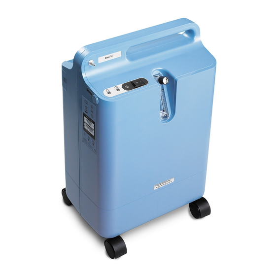
- Page 1 EverFlo Oxygen Concentrator EverFlo Q Oxygen Concentrator Service & Technical Reference Manual LO TM Page 1 & T 1039055, VER. 06 ERVICE ECHNICAL NFORMATION...
- Page 2 EVISION ISTORY Revision Description Author Updated to include Field Communications K. Carter Reformatted LO TM Page 2 & T 1039055, VER. 06 ERVICE ECHNICAL NFORMATION...
-
Page 3: Table Of Contents
Chapter 1. INTRODUCTION ......................5 EVERFLO OXYGEN CONCENTRATOR OVERVIEW ................5 SERVICE NOTICE ............................ 5 SERVICE TRAINING ..........................5 SERVICE/TECHNICAL SUPPORT STATEMENT ..................5 Chapter 2. WARNINGS & CAUTIONS ................... 6 WARNINGS ............................... 6 CAUTIONS ..............................7 Chapter 3. SPECIFICATIONS & CLASSIFICATIONS ..............8 SPECIFICATIONS ............................. - Page 4 EVERFLO AND EVERFLO Q PRESSURE REGULATOR ASSEMBLY REPLACEMENT ....50 EVERFLO ULTRAFILL COMPATIBLE PRESSURE REGULATOR ASSEMBLY REPLACEMENT ..52 MAIN PCA REPLACEMENT ........................55 8.10 SIEVE CANISTER ASSEMBLY REPLACEMENT ................59 8.11 VALVE SOLENOID REPLACEMENT ....................63 8.12 COOLING FAN REPLACEMENT ....................... 67 8.13...
-
Page 5: Chapter 1. Introduction
For more information, contact the Respironics Customer Service department @ 1-800-345-6443. SERVICE/TECHNICAL SUPPORT STATEMENT For technical assistance, please contact Philips Respironics Service and Technical Support. U.S.A. and Canada Phone: 1-800-345-6443... -
Page 6: Chapter 2. Warnings & Cautions
& C Chapter 2. ARNINGS AUTIONS Warnings and cautions are used throughout this manual to identify possible safety hazards, conditions that may result in equipment or property damage, and important information that must be considered when performing service and testing procedures on the EverFlo Oxygen Concentrator. Please read this section carefully before servicing the EverFlo Oxygen Concentrator. -
Page 7: Cautions
WARNINGS • Avoid handling the molecular sieve material. Respironics recommends the return of the sieve canister assembly to Respironics for any service that involves sieve disposal. • Use extreme caution when handling the compressor capacitor as it holds an electrical charge until is it properly discharged. -
Page 8: Chapter 3. Specifications & Classifications
& C Chapter 3. PECIFICATIONS LASSIFICATIONS SPECIFICATIONS Voltage Operational Power Oxygen Model Sound Weight Power Consum Concentrati Numbers Level Frequency ption on Zero to Maximum Flow LPM 1020000 1020001 1020002 120 VAC + 350 W 60 Hz 90 - 95.5% 45 dBA typ 31 lbs (14 kg) 1020003 At 120 VAC... - Page 9 All Models Dimensions 22.8” (58 cm) x 15” (38 cm) x 9.5” (24 cm) (H x W x D) Low Oxygen at 82% purity (For OPI models only), Very Low Oxygen Oxygen Purity Alarms at < 70% 55 o F to 90 o F (13 o C to 32 o C) Operating Temperature 29 o F to 160 o F (-34 o C to 71 o C) Storage and Transport Temperature...
-
Page 10: Chapter 4. Theory Of Operation
Chapter 4. HEORY OF PERATION This section describes the theory of operation for the EverFlo Oxygen Concentrator. PNEUMATIC OPERATION Refer to Figure 4-1 while reading the following discussion. The room air is drawn into the unit through the air inlet filter by the compressor. The compressed air is routed to the sieve beds through an electronically controlled Solenoid Valve Assembly. - Page 11 Figure 4-1: Pneumatic Block Diagram (Non-O2 Piloted) LO TM Page 11 & T 1039055, VER. 06 ERVICE ECHNICAL NFORMATION...
-
Page 12: Electrical Operation
ELECTRICAL OPERATION The EverFlo Concentrator is a medical device, which produces concentrated oxygen from room air for delivery to a patient. It uses a molecular sieve and a pressure swing adsorption process to concentrate oxygen from air. The device consists of filters, a compressor, a sieve canister module, a set of valves, a microprocessor-based electronic controller PCA, a flow meter and a cooling fan –... - Page 13 4.3.1 POWER The AC mains power, via the line cord, is brought onto the PCA and the “switched” AC is distributed to the Compressor, the Cooling Fan and to the AC to DC conversion module. The DC voltages that are generated are used to power the remaining circuitry.
-
Page 14: System Setup
Chapter 5. YSTEM ETUP NOTE Please refer to the appropriate User Manual for additional information. INTRODUCTION This section provides information regarding setup and operation of the EverFlo Oxygen Concentrator as needed for servicing, repairing, and testing the device. SYSTEM SETUP PROCEDURES 1. - Page 15 5. Press the power switch to the On [I] position. Initially, all the LEDS will illuminate and the audible alert will sound for a few seconds. After that time, only the green LED should remain lit. You can begin breathing from the device immediately even though it typically takes 10 minutes to reach oxygen purity specifications.
-
Page 16: Chapter 6. Maintenance
Chapter 6. AINTENANCE DEALER ROUTINE MAINTENANCE This section describes scheduled and routine maintenance procedures. Normal routine maintenance involves periodic checking, cleaning, and or replacing the following items as necessary: • Inlet Filter • Micro-Disk Filter • Cabinet cleaning • LPM flow setting to the prescribed level •... -
Page 17: Everflo Oxygen Concentrator Maintenance Record
EVERFLO OXYGEN CONCENTRATOR MAINTENANCE RECORD MODEL NUMBER SERIAL NUMBER DATE PURCHASED FILTERS OXYGEN CONCENTRATION DATE/HOURS/LPM (Clean & Replace as Necessary) Inlet Micro-Disk (Check Level) (Record at Each Check) CABINET FLOW SETTING (Clean and Inspect as Necessary) (Check Setting) LO TM Page 17 &... -
Page 18: System Verification Procedures
SYSTEM VERIFICATION PROCEDURES The following procedures may be performed at any time to ensure that the EverFlo Concentrator is functioning properly. 6.3.1 SYSTEM SELF TEST AND START UP TEST 1. Connect the power cord to the proper power source. 2. Turn on the unit by moving the power switch to the ON (I) position and verify the following: •... - Page 19 3. Connect the pressure gauge from the tool kit to the outlet barb. The flow ball should drop to 0.0 LPM. NOTE Be sure to hold the pressure gauge in a vertical position. 4. If the outlet pressure does not fall between 5.0 and 7.0 psig, perform steps 5 through 14. If the pressure does fall between 5.0 and 7.0 psig, remove pressure gauge, the test is now complete.
- Page 20 8. Insert a “T” from the tool kit in between the regulator and the clear oxygen tubing and connect the pressure gauge. 9. Turn the device on and set the flow meter to 5 LPM (1 LPM for units equipped with pediatric flow meters).
- Page 21 6.3.4 SYSTEM PRESSURE TEST The system pressure test is used to verify the proper operation of the EverFlo Compressor and Sieve Canister Assemblies. NOTE If pressures are not within the normal operating pressure, it does not necessarily indicate an issue with the concentrator.
- Page 22 EverFlo Normal Pressure for Normal Pressure for Model units equipped with units without Purge Purge Valves Valves 1020000 1020001 1020002 1020003 1020002BR 1020003BR 1039362 1039363 1020004 1020005 1020006 1020009 1020010 1020011 1020012 1020016 1020017 1039366 1039368 1039370 1020007 1020008 1039367 1020013 1020014 1020015...
- Page 23 10. Confirm that all peaks are within one (1) psig of each other. NOTE If the four cycles are not within specification, refer to the troubleshooting section of the service manual. 11. Turn off the EverFlo Concentrator and disconnect the pressure gauge, “T” fitting, and tubing. Reconnect the yellow tubing to the Pressure Regulator Adaptor located on the top of the Sieve Canister Assembly.
- Page 24 MODEL NUMBER OXYGEN PURITY 1020000, 1020001, > 90% 1020002, 1020003, 1020002BR, 1020003BR 1020004, 1020005, 1020006, 1020009, 1020010, 1020011, 1020012, 1020013, 1020014, 1020015, 1020016, 1020017, 1039362, 1039363 1039364, 1039365 1039366, 1039368, 1039370 1020007, 1020008, > 87% 1039367 6.3.6 MAIN PCA OXYGEN VERIFICATION (OPI UNITS ONLY) This procedure verifies that the Main PCA is operating properly.
- Page 25 6.3.7 COMPRESSOR TEST This procedure verifies if the Compressor is working properly. EQUIPMENT REQUIRED FOR OPTION 1 Item Reference Part No. Description Picture McMaster-Carr: Qty 1 White Polypropylene Barbed Tube Fitting of Part #: 5121K851 Reducing Tee for 3/8" X 1/8" X 3/8" Tube McMaster-Carr: Qty 1 Compact Plastic Needle Valve 3/8"...
- Page 26 Item Reference Part No. Description Picture Hose Clamp, Qty 5 Clamping range of 1/4” to 5/8” 18” Patient Tubing, Qty 1 TSI Flow Meter, Qty 1 High-Pressure Tygothane Polyurethane Tubing Clear, 3/8" ID, 1/2" OD, 1/8" Wall. 10’L FDA White Nylon Single Barbed Tube Fitting Adapter for 1/8”...
- Page 27 EQUIPMENT REQUIRED FOR OPTION 2 Items 1-4, 6, 9, and 10 as detailed above with the addition of the following items: Reference Part No. Description Picture Male Tube Adapter 1/8” NPT x 3/8” Barb, McMaster-Carr: Part # 5372K116 Flow Meter, Dwyer Instruments Part # RMA- ASSEMBLY INSTRUCTIONS FOR EQUIPMENT OPTION 1 1.
- Page 28 ASSEMBLY INSTRUCTIONS FOR EQUIPMENT OPTION 2 1. Connect the compressor blue outlet tube to Barbed Tube Fitting Reducing Tee (#1) and secure with a hose clamp (#6). 2. Thread the Barbed Tubing Fitting Adapter (#10) to the gauge (3) using Teflon tape. 3.
- Page 29 ASSEMBLY INSTRUCTIONS FOR EQUIPMENT OPTION 3 Option 3 is only available in SCMS (equipment not shown above). 1. Attach the TSI flow meter to the inlet filter. 2. Attach the grommet to the inlet adapter. 3. Inset the pipe nipple into a length of hose. (@ 7” in length) 4.
- Page 30 2. Remove the blue hose running from the Compressor to the Sieve Canister Assembly by carefully cutting the one-eared clamp. 3. Connect the Compressor blue outlet tube to the Test Fixture’s Barbed Tube Fitting Reducing Tee. 4. Install the Inlet Filter to the Compressor’s Inlet Boot. 5.
-
Page 31: Chapter 7. Troubleshooting & Alarms
& A Chapter 7. ROUBLESHOOTING LARMS INTRODUCTION This section provides service technicians with a troubleshooting table to determine which component(s) is any, must be replaced. INDICATORS & ALARMS COLORED LED POSSIBLE CAUSE Yellow LED is blinking. The Red LED is off The device has detected a high oxygen flow and the Audible Alarm is beeping condition. -
Page 32: Troubleshooting Table
TROUBLESHOOTING TABLE CORRECTIVE SYMPTOM CAUSE VERIFICATION ACTION • Canister to Compressor • • Low pressure Verify there are no Repair leaks in tubing failure leaks tubing and hoses • • Verify the tubing Reconnect or between the canister replace the and Compressor is tubing connected... - Page 33 CORRECTIVE SYMPTOM CAUSE VERIFICATION ACTION Pressure relief valve • • • High pressure Verify that tubing is Reposition the not kinked or tubing pinched • Replace the • Verify that the tubing damaged tubing is not damaged • Replace Valve •...
- Page 34 CORRECTIVE SYMPTOM CAUSE VERIFICATION ACTION Pressure Regulator • • • Fluctuations in Verify the flow from Replace the failure oxygen pressure regulator is correct regulator • • Fluctuation in flow Perform Outlet / ball Regulated Pressure Test • Replace the Valve •...
- Page 35 CORRECTIVE SYMPTOM CAUSE VERIFICATION ACTION • Verify the power cord • No power to LED’s • LED failure Connect the is plugged in power cord to AC power source • • Check the Verify power in wall household fuse or outlet circuit breaker •...
- Page 36 CORRECTIVE SYMPTOM CAUSE VERIFICATION ACTION • Sieve bed failure • • Low oxygen output Verify the oxygen Replace the Sieve output with a Canister calibrated oxygen analyzer • • Verify the Replace the Compressor is Compressor working properly • • Verify that there are Replace tubing no leaks...
- Page 37 CORRECTIVE SYMPTOM CAUSE VERIFICATION ACTION • Cycle failure • • Pressure relief Verify Valve Solenoid Replace Valve valve activated Assembly operation Solenoid Assembly • • • Red LED (constant) Verify Valve Solenoid Reconnect the Valve assembly wire Solenoid wiring • Low pressure harness connection harness to the Main...
- Page 38 CORRECTIVE SYMPTOM CAUSE VERIFICATION ACTION • Flow Meter failure • • Inaccurate oxygen Verify the Flow Meter Replace the Flow flow Meter can be adjusted properly • Compressor thermal • • Loss of power Verify that air flow Reposition the switch failure around concentrator concentrator to an...
-
Page 39: System Pressure Test Table
SYSTEM PRESSURE TEST TABLE CORRECTIVE SYMPTOM CAUSE VERIFICATION ACTION System Pressure Test • • • High-pressure Check oxygen Check for proper reading above 25 percentage at 5 valve cycling • Abnormal reading psig @ 60 Hz @ 5 LPM. If Low? •... -
Page 40: Chapter 8. Repair & Replacement
& R Chapter 8. EPAIR EPLACEMENT OVERVIEW This chapter illustrates the replaceable components for the EverFlo Oxygen Concentrator. Procedures for replacing the components are also provided in this chapter. NOTE Refer to the proper Testing Section for required testing after component replacement. -
Page 41: Repair Kit Reference Table
Label 1051037 RP-EverFlo Mill Branding LBLs 1051038 RP-Model 1020013 Fire Warn LBL Overlay 1053746 RP-EverFlo Overlay Kit 1056622 RP-EverFlo Q Overlay Kit Tubing 1135323 RP-EverFlo Compressor Repair Kit 1038833 RP-EverFlo OPI Concentrator Tubing 1075139 RP-EverFlo-T Pressure Regulator Assy 1132529 RP - PRI Compressor Inlet Tube Assembly... - Page 42 PART NUMBER(S) REPAIR KIT NAME 1039576 RP-EverFlo Front Cabinet Kit-230V 1050254 RP-EverFlo Q Front Cabinet Outlet 1038830 RP-EverFlo Front Cabinet DISS Outlet Hardware 1121100 RP-KIT,CABLE TIE, 11 1/2 IN LG(X1000) 1038841 RP-EverFlo Hardware 1116864 RP-Torx, T6 Insert Bit Kit 1116865 RP-Torque Driver Kit 1.5 to 15 in-lbs...
- Page 43 1038810 RP-EverFlo Rear Cabinet Assy-120V 1039577 RP-EverFlo Rear Cabinet-230V 1050253 RPKit-EverFlo 1020007 Rear Cabinet Assy 1050252 RP-EverFlo Q Rear Cabinet Sieve Canister Assembly 1038825 RP-EverFlo Canister Assy .035x11.5 NOTE: Do not use with GSE Compressor 1050248 RP-EverFlo Canister Assy .035x12.5 1052382 RP-EverFlo Canister Assy .032x12.5...
-
Page 44: Filter Cover Replacement
FILTER COVER REPLACEMENT To Remove the Filter Cover 1. Using minimal force, apply pressure to the outside of the Filter Cover. To install the Filter Cover 1. Place Filter Cover tab into slot. 2. Push the Filter Cover in until it locks. Figure 8-1: FILTER COVER REPLACEMENT LO TM Page 44... -
Page 45: Inlet Filter Replacement
INLET FILTER REPLACEMENT To remove the Inlet Filter 1. Remove the Filter Cover. Refer to the Refer to the Filter Cover Replacement section for more information. 2. Remove the Inlet Filter. To install the Inlet Filter 1. Fully seat the Inlet Filter into the Inlet Boot. 2. -
Page 46: Rear Cabinet/Power Cord Replacement
REAR CABINET/POWER CORD REPLACEMENT To remove the Rear Cabinet/Power Cord 1. Place the concentrator face down on an ESD Protected surface. 2. Remove the Filter Cover. Refer to the Filter Cover Replacement section for more information. 3. Remove the Inlet Filter. Refer to the Inlet Filter Replacement section for more information. 4. - Page 47 Figure 8-5: TIE WRAP LOCATION 8. Unclip the Main PCA shield from the Front Cabinet and push the PCA toward the bottom of the cabinet until the power switch clears the front cabinet. Figure 8-6: UNCLIP MAIN PCA 9. Lift Main PCA out of the Front Cabinet. Figure 8-7: MAIN PCA REMOVAL 10.
- Page 48 Figure 8-8: STRAIN RELIEF REMOVAL To install the Rear Cabinet/Power Cord 1. Thread the Power Cord through the hole in the Rear Cabinet. A set of bent needle nose pliers will help with the installation of the power cord. 2. Connect the Power Cord connectors to the J3 and J4 locations of the Main PCA. Refer to Figure 8-15.
-
Page 49: O 2 Quick Coupler Replacement
O 2 QUICK COUPLER REPLACEMENT To remove the O Quick Coupler 1. Remove the Filter Cover. Refer to the Filter Cover Replacement section for more information. 2. Remove the Inlet Filter. Refer to the Inlet Filter Replacement section for more information. 3. -
Page 50: Everflo And Everflo Q Pressure Regulator Assembly Replacement
EVERFLO AND EVERFLO Q PRESSURE REGULATOR ASSEMBLY REPLACEMENT To remove the Pressure Regulator Assembly 1. Remove the Filter Cover. Refer to the Filter Cover Replacement section for more information. 2. Remove the Inlet Filter. Refer to the Inlet Filter Replacement section for more information. - Page 51 Figure 8-10: PRESSURE REGULATOR ASSEMBLY REMOVAL/INSTALLATION 4. Connect the yellow pressure line to the Pressure Regulator Adaptor. Refer to Figure 8-9. 5. Install the Rear Cabinet. Refer to the Rear Cabinet/Power Cord Replacement section for more information. 6. Install the Inlet Filter. Refer to the Inlet Filter Replacement section for more information. 7.
-
Page 52: Everflo Ultrafill Compatible Pressure Regulator Assembly Replacement
EVERFLO ULTRAFILL COMPATIBLE PRESSURE REGULATOR ASSEMBLY REPLACEMENT To remove the Pressure Regulator Assembly 1. Remove the Filter Cover. Refer to the Filter Cover Replacement section for more information. 2. Remove the Inlet Filter. Refer to the Inlet Filter Replacement section for more information. 3. - Page 53 To install the Pressure Regulator Assembly 1. Using pliers, clamp the flow tubing to the Pressure Regulator Assembly. 2. Place the Pressure Regulator Assembly in place by lining the Pressure Regulator Adaptor up with the grooves in the Sieve Canister Assembly. 3.
- Page 54 Figure 8-14: CLEAR TUBING POSITION 6. Install the clear tubing to the Pressure Regulator Adapter outlet and secure with a tie wrap. 7. Connect the yellow pressure line to the Pressure Regulator Adapter. 8. Install the Rear Cabinet. Refer to the Rear Cabinet/Power Cord Replacement section for more information.
-
Page 55: Main Pca Replacement
MAIN PCA REPLACEMENT Reference Table for Original and New Release Parts, Listed by Model Number Model First Serial Sieve Bed - Sieve Bed - Main PCA - Main PCA - Number w/o Unit w/ Unit w/o Unit w/ Unit w/o Purge Valve Purge Valve Purge Valve... - Page 56 5. Remove the Power Cord Connectors from the J3 and J4 locations of the Main PCA. Refer to Figure 8-15. 6. Remove the Fan Connector from the J9 location of the Main PCA. Refer to Figure 8-15. 7. Remove the Valve Solenoid Connector from the J7 location of the Main PCA. Refer to Figure 8- 8.
- Page 57 Figure 8-16: Example PCA Equipped with LCD Hour Meter LO TM Page 57 & T 1039055, VER. 06 ERVICE ECHNICAL NFORMATION...
- Page 58 To install the Main PCA Note EverFlo devices originally equipped with the LCD PCA (see Figure 8-16) may only have LCD PCA RP kits as replacements. EverFlo devices with older PCAs, (i.e., with analog hour meters) may use the LCD PCA RP kits as replacements for faulty PCAs.
-
Page 59: Sieve Canister Assembly Replacement
8.10 SIEVE CANISTER ASSEMBLY REPLACEMENT Note The 230V EverFlo Concentrators have been updated. All 230V models will now be manufactured without a purge valve. To support this change the release of a new Main PCA and Sieve Canister were required. It is possible to install these new release repair parts into an original unit with the Purge Valve, but both the Main PCA and Sieve Canister without purge valve will need to be replaced. - Page 60 To remove the Sieve Assembly 1. Remove the Filter Cover. Refer to the Filter Cover Replacement section for more information. 2. Remove the Inlet Filter. Refer to the Inlet Filter Replacement section for more information. 3. Remove the Rear Cabinet. Refer to the Rear Cabinet/Power Cord Replacement section for more information.
- Page 61 9. Remove the Solenoid Valve Assembly from the Sieve Canister Assembly by removing the five phil- lips head screws. To install the Sieve Assembly 1. Install the Solenoid Valve Assembly. Refer to the Valve Solenoid Replacement section for more information. 2.
- Page 62 Everflo Intl OPI 230V Argentina 0008174 or higher 0058836-0058899 and 1020014 EVERFLO Q DOM OPI 120V US/CAN 0062100-0062146 1020015 EVERFLO Q DOM NON OPI 120V US/CAN 0046353 or higher 1020016 EverFlo Intl OPI 230V HK 0004389 or higher 1020017 EverFlo Intl OPI 230V SWTZ...
-
Page 63: Valve Solenoid Replacement
8.11 VALVE SOLENOID REPLACEMENT NOTE There have been three different types/manufacturers of Solenoid Valves: • SMC (air piloted, original type solenoid valve, used from initial product launch until approximately 6/13) • ASCO (air piloted, original type solenoid valve used from approximately 12/11 until 6/13) •... - Page 64 3. Secure the Valve Solenoid Assembly to the Sieve Canister Assembly by securing the five screws to 8 in-lbs. using the torque sequence listed in Refer to Figure 8-19. CAUTION The washer is important so the screw in this location does not penetrate a channel in the valve. 4.
- Page 65 5. Torque specifications for the pilot valves are 1.5 in-LBS or 1.7 cm-KG. (T6 TORX size bit.) as shown below. 1.5 in 6. Install the Sieve Canister Assembly. Refer to the Sieve Canister Assembly Replacement section for more information. 7. Install the Rear Cabinet. Refer to the Rear Cabinet/Power Cord Replacement section for more information.
- Page 66 9. Install the Filter Cover. Refer to the Filter Cover Replacement section for more information. Figure 8-20: VALVE SOLENOID ASSEMBLY REMOVAL/INSTALLATION NOTE Devices manufactured after 06/18/2013 will be equipped with the O2 piloted valve. See Section 8.2 for RP Kit P/Ns. See Section 8.10 for a Serial No. cutoff for various EverFlo models with the O2 piloted valve.
-
Page 67: Cooling Fan Replacement
8.12 COOLING FAN REPLACEMENT To remove the Cooling Fan 1. Remove the Filter Cover. Refer to the Filter Cover Replacement section for more information. 2. Remove the Inlet Filter. Refer to the Inlet Filter Replacement section for more information. 3. Remove the Rear Cabinet. Refer to the Rear Cabinet/Power Cord Replacement section for more information. - Page 68 Figure 8-21: FAN REMOVAL/INSTALLATION AND PROPER ORIENTATION 2. Connect the Cooling Fan Connector to the J9 location of the Main PCA. 3. Secure the wires using the Cooling Fan wire clip. 4. Connect the Main PCA shield to the Front Cabinet locking tab. 5.
-
Page 69: Capacitor Replacement
8.13 CAPACITOR REPLACEMENT To remove the Capacitor CAUTION DO NOT touch the capacitor terminals simultaneously until the capacitor has been completely discharged. Discharge the capacitor by shorting the two posts with an insulated screw driver. 1. Remove the Filter Cover. Refer to the Filter Cover Replacement section for more information. 2. -
Page 70: Compressor Replacement
Thomas label. This compressor should be used in all domestic TransFill units. Thomas Compressor GSSE Compressor Philips Compressor To remove the Compressor 1. Remove the Filter Cover. Refer to the Filter Cover Replacement section for more information. 2. Remove the Inlet Filter. Refer to the Inlet Filter Replacement section for more information. - Page 71 Figure 8-24: MOUNTING ROD REMOVAL 8. Disconnect the Compressor wires from the Capacitor. 9. Slightly lift the back of the compressor while threading the blue hose through the hole in the compressor mounting area in the Front Cabinet. Figure 8-25: COMPRESSOR REMOVAL 10.
- Page 72 9. Install the Filter Cover. Refer to the Filter Cover Replacement section for more information. NOTE The Philips Respironics manufactured compressors are not repairable and must be replaced. NOTE Devices manufactured after 06/18/2013 can be repaired with GSE Compressors. See Section 9.2 for RP Kit P/Ns.
- Page 73 5. Install the foam in the compressor section of cabinet if the foam was not already installed as original equipment. Figure 8-27: Assembled Kit To replace the Philips Respironics compressor’s inlet tube assembly NOTE The inlet tube assembly removal and replacement procedure detailed in this Procedure section is only applicable for Philips Respironics manufactured compressors.
- Page 74 3. Make note of the manufacturer of the compressor by using the Compressor Identification table in the Detailed Description section of this field communication. a. If the compressor is not manufactured by Philips Respironics, this procedure is not applicable. b. If the compressor is manufactured by Philips Respironics, and the inlet tube assembly requires replacement, continue with this replacement procedure.
- Page 75 5. Using side cutters, cut the two cable ties retaining the inlet tube assembly to the compressor housing. 6. Gently pull the inlet tube assembly from the compressor housing. Discard the cut cable ties. LO TM Page 75 & T 1039055, VER.
- Page 76 7. Using side cutters, cut the cable tie securing the inlet boot bellows to the inlet tube assembly. Discard the cut cable tie. 8. Discard the used inlet tube assembly Inlet Tube Installation 1. Assemble the new inlet tube assembly by sliding the silicone tube over the tee and elbow connections. Ensure the center-to-center distance from elbow to tee is approximately 4.75 inches.
- Page 77 2. Slide the inlet boot bellows (see Section 8.2) onto the tee. Secure with the included cable tie. Cut any excess cable tie and discard. 3. Insert the inlet tube assembly into the compressor housing making sure to orient the inlet boot bellows on the same side of the compressor as the valve cover barb.
- Page 78 5. Install the compressor back into the EverFlo device. LO TM Page 78 & T 1039055, VER. 06 ERVICE ECHNICAL NFORMATION...
-
Page 79: Micro-Disk Filter & Tubing Replacement
8.15 MICRO-DISK FILTER & TUBING REPLACEMENT To remove the Micro-Disk Filter & Tubing 1. Remove the Filter Cover. Refer to the Filter Cover Replacement section for more information. 2. Remove the Inlet Filter. Refer to the Inlet Filter Replacement section for more information. 3. -
Page 80: Flow Meter Replacement
4. Install the Rear Cabinet. Refer to the Rear Cabinet/Power Cord Replacement section for more information. 5. Install the Inlet Filter. Refer to the Inlet Filter Replacement section for more information. 6. Install the Filter Cover. Refer to the Filter Cover Replacement section for more information. 8.16 FLOW METER REPLACEMENT To remove the Flow Meter 1. -
Page 81: Front Cabinet Replacement
8.17 FRONT CABINET REPLACEMENT To remove the Front Cabinet 1. Remove the Filter Cover. Refer to the Filter Cover Replacement section for more information. 2. Remove the Inlet Filter. Refer to the Inlet Filter Replacement section for more information. 3. Remove the Rear Cabinet/Power Cord. Refer to the Rear Cabinet/Power Cord Replacement section for more information. - Page 82 2. Print out two labels. One must include the serial label of the device and one must contain the model number of the device (see Section 8.19). IMPORTANT The labels MUST be type written. Handwritten text is unacceptable. NOTE The following specifications are required for the new Serial and Model number labels.
- Page 83 5. Install the Flow Meter. Refer to the Flow Meter Replacement section for more information. 6. Install the Micro-Disk Filter and Tubing. Refer to the Micro-Disk Filter & Tubing Replacement section for more information. 7. Install the Compressor Assembly. Refer to the Compressor Replacement section for more information.
-
Page 84: Returns / Packaging
8.18 RETURNS / PACKAGING To package EverFlo 1. Assemble the packing carton and insert the base pulp part. Raise the right side of the base pulp part approximately 3 inches. 2. Insert the side pulp pack with the tab facing down and the hollow part facing the wall of the carton. Press the side pulp pack part down until the base pulp part sits flat on the bottom of the carton. - Page 85 4. Secure the casters with rubber bands. 5. Place the EverFlo in the carton as per the diagram on the carton. LO TM Page 85 & T 1039055, VER. 06 ERVICE ECHNICAL NFORMATION...
- Page 86 6. Place the left and right pieces of the pulp packing on the top of the EverFlo. The piece with the hole goes on the left side opposite the humidifier bottle rest. • Order return pack RP kits to return faulty devices to Philips or reuse the original device packaging. LO TM Page 86 &...
- Page 87 1. All Thomas EverFlo Compressors determined to be faulty during device servicing may be returned to Philips. See Section 8.2 for return packaging. Bulk kit users will use the return crates. GSE Compressors are not returned to Philips and should be disposed of locally.
-
Page 88: Labels
8.19 LABELS UDI Labelling Per the Unique Device Identification (UDI) initiative, medical devices are required to be labeled with certain device identifiers. The information provided on these labels allows the public to search and download information from the Global Unique Device Identification Database (GUDID) at AccessGUDID. A UDI is a unique numeric or alphanumeric code that consists of two parts: •... - Page 89 ECOMMENDED OFTWARE • Loftware Software & Print Key (Fees Apply) • For a full detailed list of Loftware supported printers and fees, please refer to: http://www.loftware.com/support/tech_printers.cfm • For software support, visit their website at www.loftware.com CTION AKEN Each label being replaced will need to display: •...
-
Page 90: Chapter 9. Testing
Chapter 9. ESTING LONG LIFE FILTER TEST This following test can be performed to determine if the EverFlo Long Life Filter has become restricted. 9.1.1 TESTING PROCEDURE 1. Power up the EverFlo Concentrator and set the flow to 5 LPM. 2. - Page 91 Figure 9-1: TEST FLOWMETER ASSEMBLY 9.2.2 TESTING PROCEDURE 1. Ensure that the unit has been run-in for a minimum of 1 hour. 2. Record the serial number and model number located on the side of the unit, in the space provided on the Testing Data Sheet.
- Page 92 11. Open the Test Flowmeter flow knob 3-4 turns. 12. Wait at least 1-3 seconds. 13. Read the Test Flowmeter value. Record the results. If the flow is greater than 10 SLPM the unit PASSES. 14. In ink, fill out the rest of the Test Data Sheet after all tests have been completed. If the unit has failed any of the tests performed, the unit must be repaired and retested according to released documentation.
-
Page 93: Everflo Test Data Sheet
EVERFLO TEST DATA SHEET NOTE All information on this data sheet should be entered in the correct location after the associated test was completed. The data sheet must then be signed in ink and dated by the technician performing tests. Circle “Pass” or “Fail”. Leave all unused boxes blank. Step 2 Step 3 Step 4... -
Page 94: Chapter 10. Tools And Equipment
Chapter 10. OOLS AND QUIPMENT You should have the following hand tools and supplies available for troubleshooting, testing, and repairing the EverFlo Concentrator. Common Hand Tools Antistatic, Electro-Static Discharge (ESD)-protected work station - minimum requirement is a grounded mat and wrist strap Phillips Screwdriver - medium (included in H646 Tool Kit) Phillips screwdriver, size “00”... -
Page 95: Acceptable Test Equipment
Supplies Cleaning Cloth Mild Detergent 10.1 ACCEPTABLE TEST EQUIPMENT 10.1.1 DIGITAL MULTIMETER Specifications • 3 1/2” digital readout Acceptable Options • Fluke 87 or better model • Any commercially available digital multimeter that meets the above specification. 10.1.2 OXYGEN ANALYZER NOTE The oxygen Analyzer used must be calibrated to meet the manufacturer’s specifications. -
Page 96: Chapter 11. Service Software
SERVICE SOFTWARE Chapter 11. 11.1 EVERFLO SERVICE TOOL 11.1.1 Required Equipment Description Version Oxygen Interface RP Kit Laptop/Desktop PC with Windows 7 Operating System (32/64 bit) or Windows 10 Operating System. EverFlo Service Tool Installer 2.0.0.1 EverFlo Service Manifest File 1.0.3 11.1.2 Download and Installation... - Page 97 4. Download the software and follow the on screen instructions in regards to file location. Install the EverFlo Service Tool 6. Allow the program to install to the default location 7. Agree to the legal licenses and click Next. 8. A couple status bars will show the progress of the download LO TM Page 97 &...
- Page 98 9. The installer will indicate the status of the Service Tool installation. Click the Extract button to install the current version driver of the FTDI drivers LO TM Page 98 & T 1039055, VER. 06 ERVICE ECHNICAL NFORMATION...
- Page 99 11. Click the Next button and continue with the procedure 12. Click the Finish button once the installer finishes loading the software. Users will be prompted to restart their computer. See screenshot below LO TM Page 99 & T 1039055, VER. 06 ERVICE ECHNICAL NFORMATION...
- Page 100 13. Repeat step 1-3 to load the Manifest ZIP file from my.respironics.com. 14. Then unzip file into location where EverFlo Service Upgrade tool was installed. For example: C:\Program Files (x86)\EverFlo Service Tool. 11.1.3 Context Definitions for Main Screen: Click on the “Help” tab and select the “About” option. This will display the Service Upgrade Tool flash screen 1.
- Page 101 11.1.4 COMMUNICATION PORT SETTINGS: 1. Connect the Oxygen Interface kit to the computer USB port. 2. Once the Communication Port has been assigned/ established to communicate with the EverFlo, locate the My Computer Icon on the computer Desktop or through Windows start menu.
- Page 102 Feature Definition Gauge and Chart Pressure measurement of the product tank in PSI Used to measure the balance and peak pressure. To be used to check the sieve canister balance. 15-27 PSI range Estimated Flow Estimation of flow rate in liters per minute from EverFlo product tank, derived from the pressure slope.
- Page 103 Inhibit Audible Alarm silence Alarm O2 Gauge Oxygen purity reported by the internal OPI sensor. OPI devices only. Keep Sensor On OPI sensor remains on as long as the device is turned on. MSP version Firmware version of the MSP microcontroller: Currently released manufacturing firmware is 3.0 and will show as 30 in the MSP version box.
- Page 104 Yellow Illuminated when the yellow LED is active. Illuminated when the red LED is active. Green Illuminated when the green LED is active. Sol C Illuminated when solenoid valve C is active and the device is equipped with a Purge valve.*See Note below Sol A Illuminated when solenoid valve A is active.
- Page 105 Feature Definition Firmware Upgrade By Identification from the PCA or By Feature of the parts contained in the EverFlo. By Identification Model and serial number imprinted on the PCA and read by the Service Tool By Feature Model type, Compressor and Solenoid valve type the unit is equipped with. A single known configuration must be found in order to upgrade the Firmware.
- Page 106 9. Verify the MSP software version is the most current. If not the most current version, then continue with the Upgrade process. 10. Select the File and then the Upgrade Firmware option. NOTE If the Upgrade Firmware option is unavailable, the Manifest file has not been properly loaded. 11.
- Page 107 16. The Service Tool will reload the information and the main screen will display. 17. The MSP version will be changed to the current release of firmware and is complete. 18. Upgrading by feature is used if the PCA was replaced in the past and PCA serial number and model number do not match the device label.
- Page 108 20. Once the firmware is upgraded retest the unit for the customer complaint. 21. If the unit passes, then continue with the repair process and final test. 22. When all the features match, a single known configuration will show in the bottom box. If not, the following message appears “There are no matching configurations”...