
Related Manuals for Epson Moverio BT-35E


Summary of Contents for Epson Moverio BT-35E
- Page 1 User's Guide Information on the Moverio Website © 2018 Epson America, Inc., 9/18 CPD-55906R1 Provides technical information. https://tech.moverio.epson.com/en/bt-35e/...
-
Page 2: Table Of Contents
Contents Safety Instructions ....... 4 Using the Belt Clip/Cable Retainer ....22 Notes on Usage . - Page 3 User's Guide Organization This guide provides information on safely using this product, basic operating methods, and trouble- User's Guide shooting. Make sure you read this guide before using the product. Start Guide Explains procedures for using this product for the first time. Symbols Used in this Guide ■...
-
Page 4: Safety Instructions
01_Chapter title Safety Instructions Do not touch the plug during a thunderstorm. Failure to comply 01_Head A For your safety, read the attached documents carefully to use the product with these precautions could result in fire or electric shock. correctly. After you have read the documents, keep them in a safe place so that you can refer to them quickly at a later date. - Page 5 Safety Instructions personnel. Also, do not disassemble or remodel the product (in- Warning Product usage precautions cluding consumable items). Many of the parts inside the product carry a high voltage and could cause fire, electric shock, accident, Do not start using this product at a high volume. Doing so or poisoning.
- Page 6 In the following situations, unplug the power supply cable, and Stop using this product if the skin that touches the product (face contact the Epson service call center. Continuing to use under and so on) feels itchy when wearing the product, or any unusual these conditions may result in fire or electric shock.
- Page 7 Safety Instructions Hold the interface unit securely or place it on a stable surface and Stop using this product if your skin feels unusual when wearing this make sure the cables are not pulled with undue force. product and consult your local dermatologist. Sometimes allergies may occur due to the coating or material of the product.
-
Page 8: Notes On Usage
01_Chapter title Notes on Usage This product uses an Si-OLED display panel. Due to the characteris- 01_Head A Caution Headset usage precautions tics of the Si-OLED, you may notice burn-in or decreasing luminance on the panel. This is not a malfunction. Do not drop this headset or treat it with unnecessary force. -
Page 9: Included Items
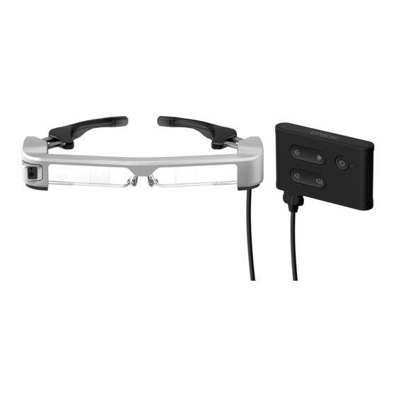
01_Chapter title Included Items 01_Head A Headset Belt clip ➡ "Headset" p.11 Cable retainer 02__lead Installation screw ➡ "Using the Belt Clip/Cable Re- tainer" p.22 Interface unit ➡ "Interface Unit" p.10 Carrying case *Not waterproof. AC adapter with plug attachment ➡... -
Page 10: Part Names And Functions
01_Chapter title Part Names and Functions 01_Head A Interface Unit LED indicator 02__lead ] (Standby) button Indicates the status of the product. Set and release standby mode and AV mute, and show/hide images. Orange: On Standby mode ➡"Standby Mode and AV Mute" p.17 Blue: Flashing No video signal detected Blue: On... -
Page 11: Interface Unit
Part Names and Functions Headset Temples Temple grip Open the temples to wear. If the temple grip gets dirty or deterio- ➡"Wearing the Headset" p.20 rates, it can be replaced. ➡"Replacing the Temple Grip" p.25 Ambient light sensor Nose pads Senses the brightness of your sur- If the nose pads get dirty, it can be roundings and automatically ad-... -
Page 12: Connecting The Interface Unit
01_Chapter title Connecting the Interface Unit and External Devices 01_Head A Inputs and Outputs The interface unit and external devices input/output the following data and power supply. 02__lead USB Type-C cables and HDMI cables are not Port Name Input/Output supplied with this product. You need to obtain •... -
Page 13: Connecting By Hdmi
Connecting the Interface Unit and External Devices Connecting by HDMI Follow the steps below to display images from external devices connected by HDMI. Connect the headset. Connect the power supply. Micro-B HDMI Connect the external device. When using the headset sensor or camera data, connect to the USB-C port. Video signals from the HDMI port have priority over video signals from the USB-C port. -
Page 14: Connecting By Usb Type-C
Connecting the Interface Unit and External Devices Connecting by USB Type-C When connecting to an external device with USB Type-C, you can use data from the headset sensors and camera as well as view the images. Also, since it can be used as a power supply source, you can perform three operations simultane- ously using one USB Type-C cable;... - Page 15 Connecting the Interface Unit and External Devices Notes on displaying images by USB Type-C When using the headset sensors or camera • This product supports DisplayPort Alternate mode (DP Alt Data from the sensors and camera built into the headset mode) for USB Type-C.
-
Page 16: Turning On/Displaying Images
01_Chapter title Turning On/Displaying Images 01_Head A When power is supplied from the Micro-B port or USB-C See the following for information on using the but- port, this product turns on. Also, when a video signal is tons. being input, the video is displayed automatically. ➡... -
Page 17: Standby Mode And Av Mute
Turning On/Displaying Images Standby Mode and AV Mute Although standby mode and AV mute will hide the im- ages and mute the audio, there are a few differences. Select the appropriate mode to suit your needs. Time to Display Power Setting Images Consumed... -
Page 18: Extended Features
01_Chapter title Extended Features 01_Head A You can access extended features by holding down two buttons at the same time. You can check the status of the extended features in the display or by using the LED indicators. 02__lead Switching between 2D and 3D display Adjusting the screen brightness automatically This product uses the side-by-side 3D display format. - Page 19 Extended Features Changing the mode setting The following three modes are available. To switch the mode, hold down the [ ] key and the [ ] button at the same time. When switching mode Power saving feature ] button LED indicator Display Mode 1 (Default setting) Enabled...
-
Page 20: Wearing The Headset
01_Chapter title Wearing the Headset 01_Head A Use both hands to open the temples, and then put • How an image is perceived varies depending on on the headset. the individual. 02__lead • You can connect earphones and microphones us- ing the 3.5 mm audio jack. -
Page 21: Wearing Over Glasses
Wearing the Headset Wearing over Glasses Using the Shaded Shield The headset can be worn over glasses. (The headset can If the surrounding ambient light is too bright to view the only be worn over glasses that are approximately 5.8 screen when wearing the headset, attach the shaded inches [147 mm] wide.) shield. -
Page 22: Using The Belt Clip/Cable Retainer
01_Chapter title Using the Belt Clip/Cable Retainer 01_Head A You can attach the interface unit to the belt by using a Connect the cables. belt clip or cable retainer. 02__lead You can also secure extra cables to the cable retainer by using a commercially available band. - Page 23 Using the Belt Clip/Cable Retainer Caution Use the same procedure to attach the cable retainer to the belt. You can secure other cables using com- • Keep the cables as close to your body as possible. Sag- mercially available bands and so on so that they do ging cables may cause accidents or injuries if they be- not catch on anything in the surrounding area.
-
Page 24: Replacing The Parts
01_Chapter title Replacing the Parts 01_Head A Attaching and Removing the Shield ■ ■ Removing■the■shield This product includes clear and shaded safety shields. If it To remove the shield, flip it up, and then push down and 02__lead is too bright to view the screen when wearing the headset, pull it towards you. -
Page 25: Replacing The Temple Grip
Replacing the Parts 01_Chapter title 01_Head A Replacing the Temple Grip Slide the replacement temple grip into the groove in the headset. 02__lead Press the part indicated by the circle ( ) and remove the tip of the temple grip. While pressing the part indicated by the circle ( Slide off the remaining temple grip. -
Page 26: Replacing The Nose Pads
Replacing the Parts Replacing the Nose Pads Pull the nose pads towards you to remove them. Attach the replacement nose pads. -
Page 27: Supported Equipment And Software
You need a dedicated SDK (Software Development Kit) *1 HDMI data transfer is not supported. to control the sensor, camera, and display from your ap- Images may not be displayed correctly at other resolu- plication. tions. See the Developer’s Guide (https://tech.moverio.epson. com/en/bt-35e/document.html) for more information. -
Page 28: Updating The Firmware
01_Chapter title Updating the Firmware 01_Head A Download the firmware to your computer from the following download site, and then update it using the Epson BT-35E Update Tool. 02__lead See the firmware release notes for more information. https://tech.moverio.epson.com/en/bt-35e/download. html... -
Page 29: Maintenance
01_Chapter title Maintenance 01_Head A Cleaning the headset Cleaning the connector ports • If you can see marks in the image or if the image is hazy, • If the connectors on the interface unit are dirty or if there 02__lead check that there is no dirt, dust, fingerprints, and so on, are foreign objects stuck to them, they may not work cor-... -
Page 30: Troubleshooting
01_Chapter title Troubleshooting 01_Head A If you think a malfunction has occurred, check the fol- The display is not hidden when you lowing. press the [ ] button 02__lead The product may be set to Mode 3 in extended features. No image is displayed Hold down the [ ] key and the [... -
Page 31: Specifications
01_Chapter title Specifications 01_Head A Product Specifications 02__lead Model Number BT-35E (H935A) Material Si-OLED Panel size 0.43" wide panel (16:9) Resolution 1280x720 Angle of view Approximately 23 degrees (diagonally) Virtual screen size 40" support (virtual viewing distance 8.2 ft [2.5 m]) Color reproduction 24 bit color (approximately 16,770,000 colors) Supported 3D... -
Page 32: Video Input
Specifications Video Input HDMI (Type A) HDMI Ver. 1.4 Resolution (frame rate) 1920 x 1080 (60 Hz/59.94 Hz), 1280 x 720 (60 Hz/59.94 Hz), 1280 x 720 (30Hz), 640 x 480 (60 Hz) EDID Supported Not supported HDCP Rev. 1.4 3D formats Not supported HDMI Data Transfer... -
Page 33: Intellectual Property Rights
02__lead Trademarks "EPSON" is a registered trademark of the Seiko Epson Corporation. "EXCEED YOUR VISION" is a registered trademark or a trademark of the Seiko Epson Corporation. Windows is a registered trademark of the Microsoft Corporation in the USA and other countries. -
Page 34: General Notes
Class B Personal Computers and Peripherals; and/or CONFORMITY CPU Boards and Power Supplies used with Class B Personal Computers We : Epson America, Inc. Located at : 3840 Kilroy Airport Way MS : 3-13 Long Beach, CA 90806 Tel : 562-981-3840 Declare under sole responsibility that the product identified herein, complies with 47CFR Part 2 and 15 of the FCC rules as a Class B digital device. - Page 35 Cet appareil numèrique de la classe B est conforme à la norme NMB-003 du Canada. Indication of the manufacturer and the importer in accordance with requirements of EU directive Manufacturer: SEIKO EPSON CORPORATION Address: 3-5, Owa 3-chome, Suwa-shi, Nagano-ken 392-8502 Japan Telephone: 81-266-52-3131 http://www.epson.com/...
-
Page 36: List Of Safety Symbols
General Notes List of Safety Symbols Approved No. Symbol mark Meaning standards The following table lists the meaning of the safety sym- IEC60417 For indoor use only No. 5957 To identify electrical equipment bols labeled on the equipment. designed primarily for indoor use. Approved IEC60417 Polarity of d.c. - Page 37 General Notes Approved No. Symbol mark Meaning standards IEC60417 Class II equipment No. 5172 To identify equipment meeting the safety requirements specified for Class II equipment according to IEC 61140. ISO 3864 General prohibition To identify actions or operations that are prohibited. ISO 3864 Contact prohibition To indicate injury that could occur...
-
Page 38: Contact List
A more up-to-date contact address can be obtained from the corresponding website listed here. If you do not find what you 02__lead need on any of these pages, please visit the main Epson home page at www.epson.com. EUROPE, MIDDLE EAST & AFRICA... - Page 39 Contact List ISRAEL ITALY KAZAKHSTAN LATVIA Epson Israel Epson Italia s.p.a. Epson Kazakhstan Rep. Office Epson Service Center Latvia http://www.epson.co.il http://www.epson.it http://www.epson.kz http://www.epson.lv LITHUANIA LUXEMBURG MACEDONIA NETHERLANDS Epson Service Center Lithuania Epson Europe B.V. Digit Computer Engineering Epson Europe B.V.
- Page 40 Epson (Middle East) http://www.epson.ae NORTH, CENTRAL AMERICA & CARIBBEAN ISLANDS CANADA COSTA RICA MEXICO ECUADOR Epson Canada, Ltd. Epson Costa Rica, S.A. Epson Mexico, S.A. de C.V. Epson Ecuador http://www.epson.ca http://www.epson.co.cr http://www.epson.com.mx http://www.epson.com.ec U. S. A. Epson America, Inc. http://www.epson.com...
- Page 41 Epson Malaysia Sdn. Bhd. http://www.epson.co.id Toyoshina Plant http://www.epson.co.kr http://www.epson.com.my http://www.epson.jp NEW ZEALAND PHILIPPINES SINGAPORE TAIWAN Epson New Zealand Epson Philippines Co. Epson Singapore Pte. Ltd. Epson Taiwan Technology & Trad- http://www.epson.co.nz http://www.epson.com.ph http://www.epson.com.sg ing Ltd. http://www.epson.com.tw THAILAND Epson (Thailand) Co.,Ltd. http://www.epson.co.th...