Advertisement
Quick Links
1 | Overview
The B430 Plug-in Telephone Communicator provides communication over the PSTN
(Public Switched Telephone Network) by directly connecting the module to the control
panel. The module provides a single telephone jack and easily installs into an on-board
connector.
You can program, diagnose, and troubleshoot the system from the control panel keypad
as well as remotely through RPS.
1
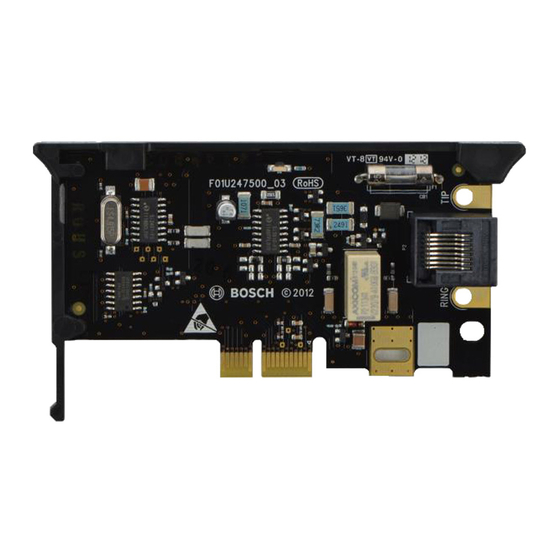
Figure 1.1: Module overview
Callout ― Description
1 ― Module handle and support leg
2 ― Line seize/ring LED
3 ― Test phone pads
4 ― RJ45 phone connector
5 ― Plug-in module retention clip opening
6 ― PCB metal contacts
2 | Install or remove the module
NOTICE!
Remove all power (AC and battery) before making any connections. Failure to
do so might result in personal injury and/or equipment damage.
1
2
3
4
5
6
2.1 | Install the module
The control panel communicates with
and provides power to the module
through the plug-in connection. Proper
installation results in the necessary
electrical and mechanical connection.
Installing the module:
1.
With the module facing the control
panel as shown below, insert the
support leg into the support hole
labeled X.
2.
Align the PCB metal contacts with
the on-board connector.
3.
Push the module into place. The
retention clip snaps closed and
secures the module in place.
Figure 2.1: Module installation
Callout ― Description
1 ― Support leg inserted into the
control panel support hole labeled X
2 ― PCB metal contacts resting on
the on-board connector
3 ― Plug-in module retention clip
2.2 | Wire the module
Connect one end of a compatible
telephone cord to the B430, and
connect the other end to an RJ31X or
RJ38X phone jack that is connected to
the phone line. The module has pads
on both sides of the board to connect
a telephone test set. Refer to Figure
2.2.
Figure 2.2: Wiring the module
Callout ― Description
1 ― Premises telephone
2 ― Incoming Telco line
3 ― Installer telephone test set
4 ― RJ45 phone connector
2.3 | Remove the module
To remove an installed module, hold the
plug-in module retention clip open with
one hand while grasping the top corners
of the module support handle with your
other hand. Pull the module out.
Advertisement

Related Manuals for Bosch B430


Summary of Contents for Bosch B430
- Page 1 2.1 | Install the module 2.2 | Wire the module The control panel communicates with The B430 Plug-in Telephone Communicator provides communication over the PSTN Connect one end of a compatible and provides power to the module (Public Switched Telephone Network) by directly connecting the module to the control telephone cord to the B430, and through the plug-in connection.
- Page 2 Copyright www.boschsecurity.com This document is the intellectual property of Bosch Security Systems, Inc. and is protected by copyright. All rights reserved. Trademarks All hardware and software product names used in this document are likely to be registered trademarks and must be treated accordingly.