Fujitsu AGU9RLF Design & Technical Manual
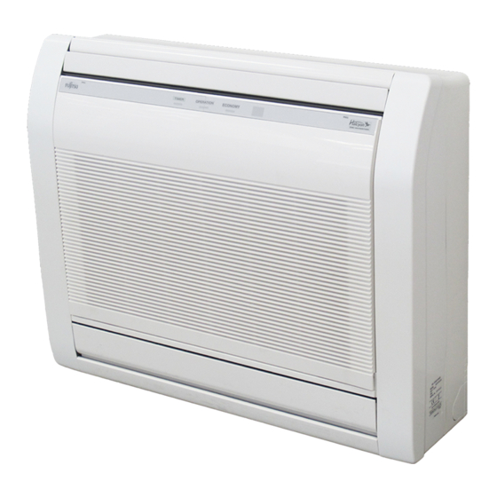
Floor type
for extra cold climate area
Hide thumbs
Also See for AGU9RLF:
- Operating manual (19 pages) ,
- Installation manual (12 pages) ,
- Design & technical manual (319 pages)

Related Manuals for Fujitsu AGU9RLF


Summary of Contents for Fujitsu AGU9RLF
- Page 1 AIR CONDITIONER Floor type DESIGN & TECHNICAL MANUAL for Extra Cold Climate Area INDOOR AGU9RLF AGU12RLF AGU15RLF OUTDOOR AOU9RLFFH AOU12RLFFH AOU15RLFFH...
-
Page 2: Indoor Unit
1. INDOOR UNIT FLOOR TYPE : AGU9RLF AGU12RLF AGU15RLF DTR_AG007E_01 2013.10.28... -
Page 3: Table Of Contents
CONTENTS 1. INDOOR UNIT 1. FEATURES ......................01 - 01 2. WIRELESS REMOTE CONTROLLER ..........01 - 04 3. SPECIFICATIONS ....................01 - 06 4. DIMENSIONS ......................01 - 07 5. WIRING DIAGRAMS ..................01 - 08 6. CAPACITY TABLE .................... -
Page 4: Features
FEATURES „ „ MODEL AGU9RLF / AOU9RLFFH AGU12RLF / AOU12RLFFH AGU15RLF / AOU15RLFFH „ „ FEATURES Energy efficiency „ Extra Cold Climate Area Model AGU9RLF AGU12RLF AGU15RLF Seasonal Energy Efficiency Ratio (SEER) 26.0 22.7 20.3 Heating Seasonal Performance Factor (HSPF) 12.4... - Page 5 Flexible & easy installation „ Piping space is wide and connection work is easy. Beneath standard window Standard concave portion Wall Half concealed Min. 940(37) Min. Min. (23- 1/4) (27- 9/16) (23-5/8) (27-9/16) Min. 730 Max. (28-3/4) (29-1/8) Max. 150 (5-7/8) (3-1/8) (7-7/8)
- Page 6 Economy operation „ Limits the maximum operation current, and the power consumption is cut down and the maximum load is suppressed. Normal operation Setting temperature Economy operation Time Air conditioner filter feature „ Apple-catechin filter Long-life ion deodorization filter - (01 - 03) -...
-
Page 7: Wireless Remote Controller
WIRELESS REMOTE CONTROLLER „ „ FEATURES 4 mode timer setup available (ON / OFF / PROGRAM / SLEEP). Easy operation. Easy to change custom code (max. 4 custom codes) by button operation. REG1U Simple function setting „ Setting of the air conditioner selection function is performed by remote controller. - Page 8 „ „ FUNCTIONS Signal transmitter MODE button FAN button MIN. HEAT button ECONOMY button SWING button TEMP. button SET button POWERFUL button TIMER ON button REG1U Start/Stop button TIMER OFF button REG1U TIMER SELECT button RESET button °C / °F switching button TIMER SLEEP button CLOCK ADJUST button TIMER CANCEL button...
-
Page 9: Specifications
SPECIFICATIONS FLOOR TYPE Type INVERTER HEAT PUMP Model name AGU9RLF AGU12RLF AGU15RLF Power source 208 / 230V ~ 60Hz Available boltage range 187 - 253V ~ 60Hz 2.64 3.52 4.16 Rated Btu/h 9000 12000 14,200 Cooling 0.90 - 3.80 0.90 - 4.20 0.90 - 5.20... -
Page 10: Dimensions
DIMENSIONS „ „ MODEL : AGU9RLF, AGU12RLF, AGU15RLF Unit: in. (mm) 7-7/8 (200) 29-1/8 (740) „ „ INSTALLATION PLACE 4 (100) or more 4 (80) or more 4 (80) or more 2 (50) or more 5 (150) or below from the floor... -
Page 11: Wiring Diagrams
WIRING DIAGRAMS „ „ MODEL : AGU9RLF, AGU12RLF, AGU15RLF TO OUTDOOR UNIT - (01 - 08) -... -
Page 12: Capacity Table
CAPACITY TABLE 6-1. COOLING CAPACITY „ „ MODEL : AGU9RLF Indoor temperature °FDB °FWB °FDB 6.88 6.10 0.26 7.77 6.09 0.27 8.20 6.72 0.27 8.78 7.05 0.27 9.38 7.21 0.28 9.67 8.02 0.28 7.79 6.88 0.44 8.80 6.87 0.45 9.28 7.58... - Page 13 „ „ MODEL : AGU15RLF Indoor temperature °FDB °FWB °FDB 11.59 9.12 0.61 13.10 9.11 0.62 13.81 10.05 0.62 14.79 10.54 0.63 15.81 10.78 0.64 16.29 11.99 0.64 12.30 9.64 0.90 13.90 9.63 0.91 14.65 10.62 0.92 15.69 11.14 0.93 16.77 11.40 0.94 17.29 12.67...
-
Page 14: Heating Capacity
6-2. HEATING CAPACITY This table is created using the maximum capacity. „ „ MODEL : AGU9RLF Indoor temperature °FDB °FDB °FWB 5.83 0.75 5.65 0.77 5.46 0.79 5.27 0.81 7.15 0.86 6.92 0.88 6.69 0.91 6.45 0.94 8.93 0.98 8.65 1.01... - Page 15 „ „ MODEL : AGU15RLF Indoor temperature °FDB °FDB °FWB 9.26 1.52 8.97 1.56 8.67 1.60 8.36 1.65 11.89 1.74 11.51 1.79 11.12 1.84 10.73 1.90 14.44 1.97 13.98 2.03 13.51 2.08 13.04 2.14 17.17 2.20 16.63 2.26 16.07 2.33 15.51 2.39 19.62...
-
Page 16: Fan Performance And Capacity
FAN PERFORMANCE AND CAPACITY 7-1. AIR VELOCITY DISTRIBUTION „ „ MODEL : AGU9RLF, AGU12RLF, AGU15RLF (ft.) (m) Unit: ft./s (m/s) Top view Vertical airflow direction louver: Up Conditions: Horizontal airflow direction louver: Center Fan speed: HIGH Operation mode: FAN Fan select: UPPER & LOWER... -
Page 17: Airflow
7-2. AIRFLOW „ „ MODEL : AGU9RLF, AGU12RLF „ Cooling Number of rotations Airflow Fan speed [r.p.m] (UPPER/LOWER) m³/h HIGH 1190/1000 m³/h 1000/850 m³/h 820/690 m³/h QUIET 660/560 zHeating „ Number of rotations Airflow Fan speed [r.p.m] (UPPER/LOWER) m³/h HIGH 1240/1040 m³/h... - Page 18 „ „ MODEL : AGU15RLF „ Cooling Number of rotations Airflow Fan speed [r.p.m] (UPPER/LOWER) m³/h HIGH 1330/1120 m³/h 1100/930 m³/h 890/750 m³/h QUIET 660/560 zHeating „ Number of rotations Airflow Fan speed [r.p.m] (UPPER/LOWER) m³/h HIGH 1330/1120 m³/h 1100/930 m³/h 860/730 m³/h...
-
Page 19: Operation Noise (Sound Pressure)
OPERATION NOISE (SOUND PRESSURE) 8-1. NOISE LEVEL CURVE „ „ MODEL : AGU9RLF „ „ Cooling Heating NC-65 NC-65 NC-60 NC-60 NC-55 NC-55 NC-50 NC-50 High High High NC-45 NC-45 NC-40 NC-40 NC-35 NC-35 NC-30 NC-30 NC-25 NC-25 Quiet Quiet... - Page 20 „ „ MODEL : AGU15RLF „ „ Cooling Heating NC-65 NC-65 NC-60 NC-60 NC-55 NC-55 High NC-50 NC-50 High NC-45 NC-45 NC-40 NC-40 NC-35 NC-35 NC-30 NC-30 NC-25 NC-25 Quiet Quiet NC-20 NC-20 NC-15 NC-15 1,000 2,000 4,000 8,000 1,000 2,000 4,000 8,000...
-
Page 21: Sound Level Check Point
8-2. SOUND LEVEL CHECK POINT Microphone Microphone ● ● Air Flow Air Flow 39-3/8in. (1m) - (01 - 18) -... -
Page 22: Electric Characteristics
ELECTRIC CHARACTERISTICS Model Name AGU9RLF AGU12RLF AGU15RLF Voltage 208 / 230 ~ Power Supply Frequency Max Operating Current Connection Cable *)Wiring Spec Limited wiring length ft. (m) 69 (21) *) Wiring Spec Selected Sample (Selected based on Japan Electrotechnical Standard and Codes Committee E0005) -
Page 23: Safety Devices
SAFETY DEVICES Model Protection form AGU9RLF AGU12RLF AGU15RLF Circuit protection Current fuse (PCB) 250V 3.15A Terminal protection Current (thermal) fuse 250V 3A OFF: 302 ± 27 °F (150 ± 15 °C) Fan motor protection Terminal protection program ON: 248 ± 27 °F (120 ± 15 °C) -
Page 24: External Input & Output
EXTERNAL INPUT & OUTPUT Connector INPUT OUTPUT REMARKS CN14 Control input See external input/output CN20 Operation status output settings for details. CN21 Error status output 11-1. EXTERNAL INPUT CONTROL INPUT (Operation/Stop or Forced stop) „ „ The air conditioner can be remotely operated by means of the following on-site work. "Operation/Stop"... - Page 25 Parts (Optional) „ Parts name Model name External connect kit UTY-XWZXZ5 Wire (External input) : UTY-XWZXZ5 - (01 - 22) -...
-
Page 26: External Output
11-2. EXTERNAL OUTPUT „ „ OPERATION STATUS OUTPUT An air conditioner operation status signal can be output. Circuit diagram example „ Indoor unit Connected unit control PC board Connector Ex.)Relay unit Ex.)Display DC 24 V Relay power supply *33 ft.(10 m) Signal Field supply *: Make the distance from the PC board to the connected unit within 33 ft.(10 m). - Page 27 „ „ ERROR STATUS OUTPUT An air conditioner error status signal can be output. Circuit diagram example „ Indoor unit Connected unit control PC board Connector Ex.)Relay unit Ex.)Display DC 24 V Relay power supply *33 ft.(10 m) Signal Field supply *: Make the distance from the PC board to the connected unit within 33 ft.(10 m).
-
Page 28: Function Settings
FUNCTION SETTINGS 12-1. INDOOR UNIT (Setting by remote controller) • The function settings of the control of the indoor unit can be changed by this procedure according to the installation conditions. Incorrect settings can cause the indoor unit to malfunction. •... - Page 29 „ „ FUNCTION DETAILS Functions 1) Filter sign 2) Vertical airflow direction range control 3) Room temperature control for cooling 4) Room temperature control for heating 5) Auto restart 6) Room temperature sensor switching 7) Remote controller custom code 8) External input control 9) Indoor unit fan control for energy saving for cooling 1) Filter sign Select appropriate intervals for displaying the filter sign on the indoor unit according to the...
- Page 30 4) Room temperature control for heating Depending on the installed environment, correction of the room temperature sensor may be required. Select the appropriate control setting according to the installed environment. ( ... Factory setting) Setting description Function number Setting value ...
- Page 31 8) External input control "Operation/Stop" mode or "Forced stop" mode can be selected. ( ... Factory setting) Setting description Function number Setting value Operation/Stop mode (Setting prohibited) Forced stop mode 9) Indoor unit fan control for energy saving for cooling Enable or disable the power-saving function by controlling the indoor unit fan rotation when the outdoor unit is stopped during cooling operation.
- Page 32 „ „ REMOTE CONTROLLER CUSTOM CODE SETTING Use the following steps to select the custom code of the remote controller. (Note that the air conditioner cannot receive a signal if the right custom code has not been set.) Press the START/STOP button until only the clock is displayed on the remote controller display.
-
Page 33: Optional Parts
OPTIONAL PARTS 13-1. CONTROLLER Exterior Parts name Summary Model No. Monitor Mo 10:00AM Large and full-dot liquid crystal Mode Set temp. screen, wide and large keys Wired remote ° F Cool High UTY-RVNUM Icon check: controller Menu easy to press, user-intuitive arrow key. - Page 34 2. OUTDOOR UNIT SINGLE TYPE : AOU9RLFFH AOU12RLFFH AOU15RLFFH DTR_AO148E_01 2013.10.28...
- Page 35 CONTENTS 2. OUTDOOR UNIT 1. SPECIFICATIONS ....................02 - 01 2. DIMENSIONS ......................02 - 02 3. REFRIGERANT CIRCUIT ................02 - 03 4. WIRING DIAGRAMS ..................02 - 05 5. CAPACITY COMPENSATION RATE FOR PIPE LENGTH AND HEIGHT DIFFERENCE ..............
-
Page 36: Specifications
SPECIFICATIONS Type INVERTER HEAT PUMP Model name AOU9RLFFH AOU12RLFFH AOU15RLFFH Power source 208 / 230V 60Hz Available voltage range 187 - 253V 60Hz Starting current Airflow Cooling 1207 (2050) 1457 (2475) 1457 (2475) rate Heating 1207 (2050) 1207 (2050) 1386 (2355) Type ×... -
Page 37: Dimensions
DIMENSIONS „ „ MODEL : AOU9RLFFH, AOU12RLFFH, AOU15RLFFH Unit: in. (mm) Top view 13/16 (20) 31-1/8 (790) 2-9/16 (65) 11/16 (18) 11-7/16 (290) 7/8 (23) 13-7/8 (352) Front view Side view 21-1/4 (540) Airflow 1 (25) hole 3/8 (10) 8-1/4 (209) hole 2-3/16 (55) -
Page 38: Refrigerant Circuit
REFRIGERANT CIRCUIT „ „ MODEL : AOU9RLFFH, AOU12RLFFH Heat exchanger 3-Way ( INDOOR ) valve 2-Way valve Muffler Muffler 4-Way valve Strainer Acccumlator Expansion valve Heat exchanger Strainer ( OUTDOOR ) Cooling Heating : Thermistor (Discharge Temp.) : Thermistor (Outdoor Temp.) : Thermistor (Heat Exchanger Out Temp.) : Thermistor (Room Temp.) : Thermistor (Pipe Temp.) - Page 39 „ „ MODEL : AOU15RLFFH Heat exchanger 3-Way ( INDOOR ) valve 2-Way valve Muffler Muffler 4-Way valve Strainer Expansion valve Heat exchanger Strainer ( OUTDOOR ) Cooling Heating : Thermistor (Discharge Temp.) : Thermistor (Outdoor Temp.) : Thermistor (Heat Exchanger Out Temp.) : Thermistor (Room Temp.) : Thermistor (Pipe Temp.) Refrigerant pipe diameter...
-
Page 40: Wiring Diagrams
WIRING DIAGRAMS „ „ MODEL : AOU9RLFFH, AOU12RLFFH - (02 - 05) -... - Page 41 „ „ MODEL : AOU15RLFFH - (02 - 06) -...
-
Page 42: Capacity Compensation Rate For Pipe Length And Height Difference
CAPACITY COMPENSATION RATE FOR PIPE LENGTH AND HEIGHT DIFFERENCE „ „ MODEL : AOU9RLFFH, AOU12RLFFH Pipe length (m) COOLING 7.5m 17ft. 25ft. 33ft. 50ft. 67ft. 50ft. 0.893 0.909 Û 1 33ft. 0.955 0.908 0.924 Indoor unit is higher than 7.5m 25ft. - Page 43 „ „ MODEL : AOU15RLFFH Pipe length (m) COOLING 7.5m 17ft. 25ft. 33ft. 50ft. 67ft. 50ft. 0.951 0.950 Û 1 33ft. 0.979 0.967 0.966 Indoor unit is higher than 7.5m 25ft. 0.988 0.983 0.971 0.970 outdoor unit. 17ft. 0.994 0.992 0.987 0.975 0.974...
-
Page 44: Additional Charge Calculation
ADDITIONAL CHARGE CALCULATION „ „ MODEL : AOU9RLFFH, AOU12RLFFH Refrigerant type R410A lbs. oz. 2lbs.10oz. Refrigerant amount 1200 „ Refrigerant charge 49 or less 66 (MAX) Pipe length 15 or less 20 (MAX) 0.22oz./ft. (20g/m) Additional charge „ „ MODEL : AOU15RLFFH Refrigerant type R410A... -
Page 45: Airflow
AIRFLOW „ „ MODEL : AOU9RLFFH „ Cooling Number of Airflow rotations (r.p.m.) 2050 1207 „ Heating Number of Airflow rotations (r.p.m.) 2050 1207 „ „ MODEL : AOU12RLFFH „ Cooling Number of Airflow rotations (r.p.m.) 2475 1050 1457 „ Heating Number of Airflow... - Page 46 „ „ MODEL : AOU15RLFFH „ Cooling Number of Airflow rotations (r.p.m.) 2475 1050 1457 „ Heating Number of Airflow rotations (r.p.m.) 2355 1000 1386 - (02 - 11) -...
-
Page 47: Operation Noise
OPERATION NOISE 8-1. NOISE LEVEL CURVE „ „ MODEL : AOU9RLFFH „ „ Cooling Heating NC-65 NC-65 NC-60 NC-60 NC-55 NC-55 NC-50 NC-50 NC-45 NC-45 NC-40 NC-40 NC-35 NC-35 NC-30 NC-30 NC-25 NC-25 NC-20 NC-20 NC-15 NC-15 1,000 2,000 4,000 8,000 1,000 2,000... - Page 48 „ „ MODEL : AOU15RLFFH „ „ Cooling Heating NC-65 NC-65 NC-60 NC-60 NC-55 NC-55 NC-50 NC-50 NC-45 NC-45 NC-40 NC-40 NC-35 NC-35 NC-30 NC-30 NC-25 NC-25 NC-20 NC-20 NC-15 NC-15 1,000 2,000 4,000 8,000 1,000 2,000 4,000 8,000 Octave band center frequency,Hz Octave band center frequency,Hz - (02 - 13) -...
-
Page 49: Sound Level Check Point
8-2. SOUND LEVEL CHECK POINT 39-3/8in. (1m) - (02 - 14) -... -
Page 50: Electric Characteristics
ELECTRIC CHARACTERISTICS Model name AOU9RLFFH AOU12RLFFH AOU15RLFFH Voltage 208 / 230 ~ Power supply Frequency 11.8 14.8 Starting Current MAX. CKT. BKR *1) Wiring Spec.: Power Cable *1) Wiring Spec.: Selected Sample (Selected based on Japan Electrotechnical Standard and Codes Committee E0005) MCA : Min Circuit Amp (Calculation based on UL1995) MAX. -
Page 51: Safety Devices
SAFETY DEVICES Model Protection form AOU9RLFFH AOU12RLFFH AOU15RLFFH 250V 20A Current fuse 250V 25A (Near the terminal) 250V 5A Circuit protection 250V 15A 250V 10A Current fuse (Main printed circuit board) 250V 3.15A 250V 3.15A Thermal protection OFF: 212 ± 27 °F (100 ± 15 °C) Fan motor protection program ON: 203 ±...