Honeywell T6 Pro Installation Instructions Manual
Hide thumbs
Also See for T6 Pro:
- Installation manual ,
- Installation instructions manual (36 pages) ,
- User manual (31 pages)
Table of Contents
Advertisement
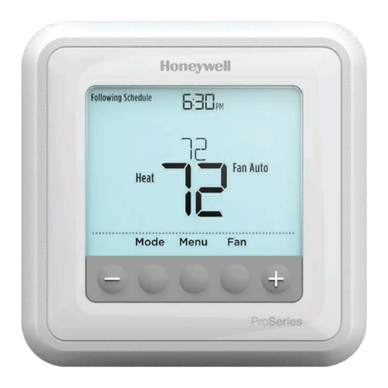
T6 Pro
Programmable Thermostat
Installation Instructions
Package Includes:
• T6 Pro Thermostat
• UWP™ Mounting System
• Honeywell Standard Installation
Adapter (J-box adapter)
• Honeywell Decorative Cover Plate –
Small; size 4-49/64 in x 4-49/64 in x
11/32 in (121 mm x 121 mm x 9 mm)
• Screws and anchors
• 2 AA Batteries
• Installation Instructions and User
Guide
Optional Cover Plate installation
NOTE: If Optional Cover Plate is not
required, see "UWP Mounting System
installation" on next page.
Use the Optional Cover Plate when:
• Mounting the thermostat to an
electrical junction box
• Or when you need to cover paint gap
from old thermostat.
1. Separate the Junction Box Adapter
from the Cover Plate. See Figure 1.
2. Mount the Junction Box Adapter to
the wall or an electrical box using any
of the eight screw holes. Insert and
tighten mounting screws supplied with
Cover Plate Kit. Do not overtighten. See
Figure 2. Make sure the Adapter Plate
is level.
3. Attach the UWP by hanging it on the
top hook of the Junction Box Adapter
and then snapping the bottom of the
UWP in place. See Figure 3.
4. Snap the Cover Plate onto the Junction
Box Adapter. See Figure 4.
1
2
Use 2x
supplied
screws #6
5/8"
4
3
Advertisement
Table of Contents

Related Manuals for Honeywell T6 Pro


Summary of Contents for Honeywell T6 Pro
-
Page 1: Programmable Thermostat
• T6 Pro Thermostat • UWP™ Mounting System • Honeywell Standard Installation Adapter (J-box adapter) • Honeywell Decorative Cover Plate – Small; size 4-49/64 in x 4-49/64 in x 11/32 in (121 mm x 121 mm x 9 mm) • Screws and anchors •... -
Page 2: Uwp Mounting System Installation
UWP Mounting System installation 5. Before starting, turn the power off at the breaker box or switch. Open package to find the UWP. See Figure 5. 6. Position the UWP on wall. Level and mark hole positions. See Figure 6. Drill holes at marked positions, and then lightly tap supplied wall anchors into the wall using a hammer. -
Page 3: Wiring Terminal Designations
Rc terminal, set the slider to the down position (2 wires). NOTE: Slider Tabs for U terminals should be left in place for T6 Pro models. R/Rc slider tab Wiring terminal designations Heat Pump fault input... -
Page 4: Forced Air And Hydronics
Wiring conventional systems: forced air and hydronics Shaded areas below apply only to TH6320U/TH6220U or as otherwise noted. 1H/1C System (1 transformer) 1H/1C System (2 transformers) Power [1] Power (heating transformer) [1] [R+Rc joined by Slider Tab] [2] Power (cooling transformer) [1] Compressor contactor Compressor contactor 24VAC common [3]... - Page 5 Wiring heat pump systems Shaded areas below apply only to TH6320U/TH6220U or as otherwise noted. 1H/1C Heat Pump System 3H/2C Heat Pump System (TH6320U only) [10] Power [1] Power [1] [R+Rc joined by Slider Tab] [2] [R+Rc joined by Slider Tab] [2] Compressor contactor Compressor contactor (stage 1) 24VAC common [3]...
-
Page 6: Thermostat Mounting
Thermostat mounting 1. Push excess wire back into the wall opening. 2. Close the UWP door. It should remain closed without bulging. 3. Align the UWP with the thermostat, and push gently until the thermostat snaps in place. 4. Turn the power on at the breaker box or switch. -
Page 7: Fan Operation Settings
System operation settings 1 Press the Mode button to cycle to the next available System mode. 2 Cycle through the modes until the required System mode is displayed and leave it to activate. NOTE: Available System modes vary by model and system settings. -
Page 8: Advanced Setup Options
Installer setup (ISU) 1 Press and hold CENTER and buttons for approximately 3 seconds to enter advanced menu. 2 Press Select to enter ISU. 3 Press Select to cycle through menu setup options. 4 Press to change values or select from available options. - Page 9 0 °F to 5 °F 0.0 °C to 2.5 °C Note: Differential is NOT deadband. Honeywell uses an advanced algorithm that fixes deadband at 0 °F. The differential setting is the minimum number of degrees from set-point needed to switch from the last mode running (heat or cool) to the opposite mode when the thermostat is in auto-changeover.
- Page 10 Advanced setup options (ISU) # ISU ISU Name ISU Options (factory default in bold) Compressor Protection 0 = Off 1 - 5 minutes Adaptive Intelligent Recovery 0 = No 1 = Yes Note: Adaptive Intelligent Recovery (AIR) is a comfort setting. Heating or cooling equipment will turn on earlier, ensuring the indoor temperature will match the setpoint at the scheduled time.
-
Page 11: Installer System Test
Installer system test To perform a System Test: 1 Press and hold CENTER and buttons for approximately 3 seconds to enter advanced menu. 2 Use to go to TEST. Press Select to enter System Test. 3 Use to change between Heat, Cool, Fan, Em Heat, or Ver (thermostat version information). -
Page 12: Specifications
Specifications Temperature Ranges Heat: 40 °F to 90 °F (4.5 °C to 32.0 °C) Cool: 50 °F to 99 °F (10.0 °C to 37.0 °C) Working Ambient Temperature 32 °F to 120 °F (0 C° to 48.9 °C) Operating Ambient Temperature 37 °F to 102 °F (2.8 °C to 38.9 °C) Shipping Temperature -20 °F to 120 °F (-28.9 °C to 48.9 °C) -
Page 13: Troubleshooting
Troubleshooting If you have difficulty with your thermostat, please try the following suggestions. Most problems can be corrected quickly and easily. Display is • Check circuit breaker and reset if necessary. blank • Make sure power switch for heating & cooling system is on. •... -
Page 14: Customer Assistance
Customer assistance For assistance with this product, please visit customer.honeywell.com. Or call Honeywell Customer Care toll-free at 1-800-468-1502. Pull to remove the thermostat from the UWP. Home and Building Technologies In the U.S.:...