Advertisement
Quick Links
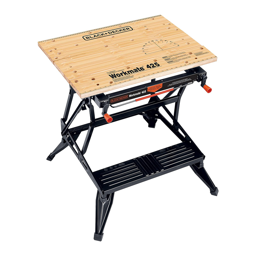
Workmate
REAR JAW
MÂCHOIRE ARRIÈRE
MORDAZA TRASERA
SNAP-IN KNOBS
BOUTONS À
ENCLENCHEMENT RAPIDE
MANGOS DE LA MANIVELA
RELEASE LEVER
LEVIER DE DÉGAGEMENT
PALANCA DE LIBERACIÓN
FOLDING LEGS
PIEDS ESCAMOTABLES
PATAS PLEGABLES
BEFORE RETURNING THIS PRODUCT
FOR ANY REASON PLEASE CALL
1-800-54-HOW-TO (544-6986)
IF YOU SHOULD EXPERIENCE A PROBLEM
WITH YOUR BLACK & DECKER PRODUCT,
CALL 1-800-54-HOW-TO (544-6986)
BEFORE YOU CALL, HAVE THE FOLLOWING INFORMATION AVAILABLE, CATALOG No., TYPE No., AND
DATE CODE. IN MOST CASES, A BLACK & DECKER REPRESENTATIVE CAN RESOLVE YOUR
PROBLEM OVER THE PHONE. IF YOU HAVE A SUGGESTION OR COMMENT, GIVE US A CALL. YOUR
FEEDBACK IS VITAL TO BLACK & DECKER.
SAVE THIS MANUAL FOR FUTURE REFERENCE.
VEA EL ESPAÑOL EN LA CONTRAPORTADA.
INSTRUCTIVO DE OPERACIÓN, CENTROS DE SERVICIO Y PÓLIZA DE GARANTÍA.
ADVERTENCIA: LÉASE ESTE INSTRUCTIVO ANTES DE USAR EL PRODUCTO.
Cat No. WM425 Type 5
Copyright © 2005 Black & Decker
WARNING: Read and understand all instructions. Failure to follow all instructions
listed below may result in serious personal injury.
1. Do not load with more than 550 pounds.
2. Do not apply an unbalanced load which could cause the work center to tip over.
3. Do not use the work center as a stepladder or standing platform. Do not use the lower
platform as a step when the work center is in "Workbench" position. The footboard is a
foot REST only.
4. Do not store work center outdoors or in a damp location.
5. Avoid applying excessive force when clamping with the swivel pegs.
6. Be sure that the legs are fully open (for workbench height) and be sure that the table
locks in position.
7. When using a power tool with the work center, follow the safety instructions in the
tool's instruction manual.
8. Always wear safety glasses when operating power tools.
9. An even pressure of the vise jaws on the workpiece is essential. Tighten both crank
handles uniformly.
10. When assembling your work center, use only the special plastic socket wrench
provided. Use of other wrenches or sockets can damage your work center.
SAVE THESE INSTRUCTIONS FOR FUTURE USE.
ASSEMBLY
®
1. The Workmate
425 work center comes partially assembled. Empty the carton
completely onto the floor and identify all the components. (Fig. 1)
2. Assemble two top blocks to the underside of the rear jaw by fitting the raised posts on
the top blocks into the smaller holes of the rear jaw. Insert bolts through the rear jaw
and into top blocks and tighten with supplied wrench. (Fig. 2)
3. Assemble top blocks to middle jaw the same as rear jaw. (Fig. 3)
4. Remove the white clip from the end of each vise screw and discard. (Clip is for
protection of part only.)
5. Aligning the hole in the vise crank with the hole in the vise screw, push the vise crank
onto the vise screw end (protruding from the front of the vise jaw bracket). Using a
hammer, drive the supplied pin into the aligned holes. Repeat this procedure for the
installation of the other vise crank. (Fig. 4)
6. Complete the assembly by pushing the snap-in knobs into the holes in the vise cranks.
(Fig. 5)
7. Install the front vise jaw on top of the top blocks so that the small holes at each end of
the vise jaw fit down over the posts on the top side of the blocks. With the jaw
positioned as described above insert into the frame as shown in figure 6. Insert a bolt
into the holes in the jaw and tighten them securely into the holes in the pivot nut. Use
the socket wrench provided.
®
8. Tip the front of the Workmate
up and rest it against your knee as shown in Fig. 7. Pull
upwards on both left and right release levers to unlock Workmate
hands, push the top of the Workmate
with your other hand until the frame locks in place. (Fig.7b) Note: New Workmate
stiff and require more effort to raise into the locked working position. To close the
®
Workmate
for storage, pull upward on the two release levers to unlock the
®
Workmate
. While holding the levers up pull back and down to close the Workmate
(Fig.7c)
FEATURES & APPLICATIONS
VERTICAL CLAMPING
9. Pull vertical locking bar toward yourself and lift front vise jaw until it is in vertical, locked
position Note: Rear jaw must be in middle "keyhole" position. (Fig. 8)
CHANGING THE INDEXED POSITION OF THE REAR JAW
10. Install rear jaw in one of three possible indexed "keyhole" positions by inserting the
indexing lug into a keyhole in the vise jaw bracket. Secure the rear jaw by moving rear
jaw to the back of the key hole. (Fig. 9)
®
425 TYPE 5
MIDDLE JAW
MÂCHOIRE CENTRALE
MORDAZA MEDIA
FRONT VISE JAW
MÂCHOIRE AVANT
MORDAZA FRONTAL
CRANK
MANIVELLE
MANIVELA
VERTICAL LOCKING BAR
BARRE DE VERROUILLAGE
VERTICALE
BARRA DE FIJACION VERTICAL
FOOTREST (NO STEP)
REPOSE-PIED (PAS UN MARCHE-PIED)
DESCANSO PARA LOS PIES (NO ESCALON)
Form # 632231-00
(APR-05)
Printed in China
®
(Fig. 7a). Using both
®
up and away from you while holding the footrest
INSTALLING THE MIDDLE JAW
11. With front jaw cranked to the front of the work center, insert the indexing lugs of the
middle jaw into the front keyholes. Rear jaw is then installed in the back keyholes. Turn
crank handle clockwise to tighten. (Fig 10)
SWIVEL PEGS
12. The four supplied swivel pegs can be used in any of the holes in the front and rear jaws.
The pegs are used to extend the size of your Workmate's holding capacity. (Fig 11)
Fig.1
3 Jaws
3 mâchoires
3 mordazas
Workmate Frame
Châssis de l'étau-établi
Estructura
2 Vise Screws
2 tiges filetées
2 Tornillos de prensa
2 Pivot Nut
2 écrous de pivot
2 Tuercas de giro
Fig. 2
Fig. 3
Fig. 5
Fig. 7, 7a, 7b, 7c
Fig. 7
Fig. 8
SERVICE INFORMATION
All Black & Decker Service Centers are staffed with trained personnel to provide customers
with efficient and reliable power tool service. Whether you need technical advice, repair, or
genuine factory replacement parts, contact the Black & Decker location nearest you. To find
your local service location, refer to the yellow page directory under "Tools—Electric" or call:
1-800-54-HOW TO. (544-6986)
IMPORTANT: To assure product SAFETY and RELIABILITY, repairs, maintenance and
adjustment should be performed by Black & Decker Service Centers or other qualified service
organizations, always using identical replacement parts.
FULL TWO-YEAR HOME USE WARRANTY
Black & Decker (U.S.) Inc. warrants this product for two years against any defects in material
or workmanship. The defective product will be replaced or repaired at no charge in either of
two ways.
®
are
The first, which will result in exchanges only, is to return the product to the retailer from whom
it was purchased (provided that the store is a participating retailer). Returns should be made
within the time period of the retailer's policy for exchanges (usually 30 to 90 days after the
®
.
sale). Proof of purchase may be required. Please check with the retailer for their specific
return policy regarding returns that are beyond the time set for exchanges.
The second option is to take or send the product (prepaid) to a Black & Decker owned or
authorized Service Center for repair or replacement at our option. Proof of purchase may be
required. Black & Decker owned and authorized Service Centers are listed under "Tools-
Electric" in the yellow pages of the phone directory.
This warranty does not apply to accessories. This warranty gives you specific legal rights and
you may have other rights which vary from state to state. Should you have any questions,
contact the manager of your nearest Black & Decker Service Center. This product is not
intended for commercial use.
FREE WARNING LABEL REPLACEMENT: If your warning labels become illegible or are
missing, call 1-800-544-6986 for a free replacement.
Imported by
Black & Decker (U.S.) Inc.,
701 E. Joppa Rd.
Towson, MD 21286 U.S.A.
Wrench
4 Top Blocks
Clé
4 blocs supérieurs
Llave
4 Bloques superiores
6 Bolts
2 front Blocks
6 boulons
2 blocs avant
6 Tornilos
2 bloques frontales
2 Pins
2 tiges
2 Snap-in Knobs
2 Pernos
2 poignées de manivelle
2 Perillas a presión
4 Swivel Pegs
4 mordaches orientables
4 Topes giratorios
Fig. 4
Fig. 6
Fig. 7b
Fig. 7a
Fig. 9
Fig. 10
Fig. 11
2 Cranks
2 manivelles
2 Manivelas
Fig. 7c
See 'Tools-Electric'
– Yellow Pages –
for Service & Sales
Advertisement

Related Manuals for Black & Decker Workmate 425 TYPE 5


Summary of Contents for Black & Decker Workmate 425 TYPE 5
- Page 1 INSTALLING THE MIDDLE JAW 11. With front jaw cranked to the front of the work center, insert the indexing lugs of the middle jaw into the front keyholes. Rear jaw is then installed in the back keyholes. Turn crank handle clockwise to tighten. (Fig 10) ®...
- Page 2 AVANT DE RETOURNER CE PRODUIT POUR QUELQUE ANTES DE DEVOLVER ESTE PRODUCTO POR RAISON QUI SOIT, VEUILLEZ APPELER AU CUALQUIER RAZÓN, POR FAVOR LLAME AL 1-800-54-HOW-TO (544-6986) (55)5326-7100 AVERTISSEMENT : Assurez-vous de lire et de comprendre toutes les directives. Négliger ADVERTENCIA: Lea y comprenda todas las instrucciones.