Table of Contents
Advertisement
Quick Links
Technical Manual
Of
Intel Bay Trail Series CPU
Based
SBC
NO.G03-NF711-F
Revision: 1.0
Release date: January 8, 2018
Trademark:
* Specifications and Information contained in this documentation are furnished for information use only, and are
subject to change at any time without notice, and should not be construed as a commitment by manufacturer.
Advertisement
Table of Contents

Related Manuals for JETWAY JNF711-2807


Summary of Contents for JETWAY JNF711-2807
- Page 1 Technical Manual Intel Bay Trail Series CPU Based NO.G03-NF711-F Revision: 1.0 Release date: January 8, 2018 Trademark: * Specifications and Information contained in this documentation are furnished for information use only, and are subject to change at any time without notice, and should not be construed as a commitment by manufacturer.
- Page 2 Environmental Protection Announcement Do not dispose this electronic device into the trash while discarding. To minimize pollution and ensure environment protection of mother earth, please recycle.
-
Page 3: Table Of Contents
TABLE OF CONTENT ENVIRONMENTAL SAFETY INSTRUCTION ............... iv USER’S NOTICE ........................v MANUAL REVISION INFORMATION ................... v ITEM CHECKLIST ........................ v CHAPTER 1 INTRODUCTION OF THE MOTHERBOARD FEATURE OF MOTHERBOARD ................1 SPECIFICATION ....................2 LAYOUT DIAGRAM ....................3 CHAPTER 2 HARDWARE INSTALLATION JUMPER SETTING.................... -
Page 4: Environmental Safety Instruction
Environmental Safety Instruction Avoid the dusty, humidity and temperature extremes. Do not place the product in any area where it may become wet. 0 to 60 centigrade is the suitable temperature. (The figure comes from the request of the main chipset) ... -
Page 5: User's Notice
USER’S NOTICE COPYRIGHT OF THIS MANUAL BELONGS TO THE MANUFACTURER. NO PART OF THIS MANUAL, INCLUDING THE PRODUCTS AND SOFTWARE DESCRIBED IN IT MAY BE REPRODUCED, TRANSMITTED OR TRANSLATED INTO ANY LANGUAGE IN ANY FORM OR BY ANY MEANS WITHOUT WRITTEN PERMISSION OF THE MANUFACTURER. -
Page 6: Chapter 1 Introduction Of The Motherboard
Chapter 1 Introduction of the Motherboard Feature of Motherboard ® Onboard Intel Bay Trail Series Processor, with low power consumption never denies high performance 1* 5V DC-IN power Onboard 2GB DDR3L DRAM Onboard 1* full-size Mini-PCIE/MSATA slot ... -
Page 7: Specification
Specification Spec Description PCB size: 1.8’’ (84 mm x 55 mm) Design ® Embedded CPU Integrated with Intel Bay Trail series CPU (TDP: 4.3W/6W) Onboard 2G un-buffered DRAM Memory 1 * full-size Mini-PCIE/MSATA shared slot Expansion Slot ... -
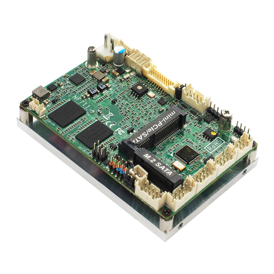
Page 8: Layout Diagram
Layout Diagram Internal Diagram-Front Side: LAN_LED VGA Port eDP Port USB 3.0 Wafer Wafer SMBUS Header Header Wafer DC-in Power Connector Wafer LCD_VDD USB 2.0 Wafers GPIO Wafer Full-size Mini-PCIE/MSATA Slot M.2 SATA ( ) MPEST Slot ( ) COM1 Serial Port Buzzer Wafer... - Page 9 Internal Diagram-Back Side: Intel CPU Onboard DRAM Note: CPU is the most important part of the board and very fragile to any possible harm. Make sure that there is no damage to the CPU during any installation procedures!
- Page 10 Connectors, Wafers & Headers Name Description DCIN Internal 5V DC–in power connector 2-pin Block USB30 USB 3.0 port wafer 5-pin Block USB20/21/22 USB 2.0 port wafer X3 4-pin Block Embedded display port wafer 20-pin Block VGA port wafer 10-pin Block SMBUS SMBUS header 4-pin Block...
-
Page 11: Chapter 2 Hardware Installation
Jumper Jumper Name Description JBAT Pin (1-2): Clear CMOS RAM Settings 6-Pin Block Pin (3-4): Reset RTC Pin (5-6): Flash Descriptors Override AT_MODE AT/ATX Mode Select 3-Pin Block LCD_VDD eDP Port LCD VDD Select 3-Pin Block Chapter 2 Hardware Installation 2-1 Jumper Setting Pin 1&2 of JBAT (6-pin): Clear CMOS RAM Setting →... - Page 12 Pin 3&4 of JBAT (6-pin): Reset RTC Select → Pin (3&4) of JBAT Reset RTC Pin 1 3-4 Open: Normal; Pin 1 3-4 Closed: Reset RTC. JBAT Pin 5&6 of JBAT (6-pin): Flash Deacriptors Override Select → Pin (5&6) of JBAT Flash Override Pin 1 5-6 Open:Enable Security Measures...
- Page 13 AT_MODE (3-pin): AT Mode /ATX Mode Select → AT_MODE AT/ATX Mode Select 1-2 Closed: ATX Mode Select(Defualt); 2-3 Closed: AT Mode Select. AT_MODE *ATX Mode Selected: Press power button to power on after power input ready; AT Mode Selected: Directly power on as power input ready. LCD_VDD (3-pin): eDP LCD VDD Select →...
-
Page 14: Connectors, Wafers And Headers
Connectors, Wafers and Headers (1) DCIN(2-pin) : Internal 5V DC-in power connector Pin1 Pin No. Definition DCIN (2) USB30 (5-pin): USB 3.0 Port Wafer Pin 1 USB30... - Page 15 (3) USB20/ USB21/ USB22 (4-pin): USB 2.0 Port Wafer DATA+ DATA- USB20 USB22 Pin 1 USB21 (4) EDP (20-pin): EDP Wafer Pin1 Pin NO. Pin Define Pin NO. Pin Define Pin 1 LCD_VDD Pin 2 Pin 3 LCD_VDD Pin 4 DATA1_N Pin 5 Pin 6...
- Page 16 (5) VGA (10-pin): VGA Wafer Pin 1 (6) SMBUS (4-pin): SMBUS Header Pin 1 SMBUS (7) LAN_LED (4-pin): LAN Activity LED Header Pin 1 LAN_LED...
- Page 17 (8) LAN (8-pin): LAN Wafer MDI_2_N MDI_3_N MDI_2_P MDI_3_P MDI_0_N MDI_1_N MDI_0_P MDI_1_P Pin 1 (9) GPIO (10-pin): GPIO Wafer GPIO7 GPIO6 GPIO4 GPIO5 GPIO3 GPIO2 GPIO0 GPIO1 GPIO Pin 1 (10) FP_AUDIO (9-pin): Line-Out, MIC-In Wafer This header connects to Front Panel Line-out, MIC-In connector with cable. LINEOUT_JD LINEOUT_L JD_SENSE...
- Page 18 (11) JW_FP (9-pin): Front Panel Header Pin 1 JW_FP (12) BUZZ(2-pin): Buzzer Wafer BUZZ Pin 1...
- Page 19 (13) COM1/2 (9-pin): Serial Port Wafers : COM1 RS232/422/485 Serial Port Wafer; : COM2 RS232 Serial Port Wafer. COM1 Pin 1 Pin 1 COM1: RS232/422/485 COM2: Serial Port RS232 Serial Port COM2 Pin NO. RS232 *RS422 *RS485 Pin 1 DATA- Pin 2 DATA+ Pin 3...
-
Page 20: Chapter 3 Introducing Bios
Chapter 3 Introducing BIOS Notice! The BIOS options in this manual are for reference only. Different configurations may lead to difference in BIOS screen and BIOS screens in manuals are usually the first BIOS version when the board is released and may be different from your purchased motherboard. Users are welcome to download the latest BIOS version form our official website. -
Page 21: Bios Menu Screen
BIOS Menu Screen The following diagram show a general BIOS menu screen: Menu Bar General Help Items Current Setting Value Menu Items Function Keys BIOS Menu Screen... -
Page 22: Function Keys
Function Keys In the above BIOS Setup main menu of, you can see several options. We will explain these options step by step in the following pages of this chapter, but let us first see a short description of the function keys you may use here: ... -
Page 23: Memu Bars
3-5 Menu Bars There are six menu bars on top of BIOS screen: Main To change system basic configuration Advanced To change system advanced configuration Chipset To change chipset configuration Security Password settings Boot To change boot settings Save & Exit Save setting, loading and exit options. -
Page 24: Main Menu
Main Menu Main menu screen includes some basic system information. Highlight the item and then use the <+> or <-> and numerical keyboard keys to select the value you want in each item. System Date Set the date. Please use [Tab] to switch between date elements. System Time Set the time. -
Page 25: Advanced Menu
3-7 Advanced Menu OS Selection The optional settings: [Windows 8.X]; [Linux/Android]; [Windows 7]. * Note: User need to go to this item to select the OS mode before installing corresponding OS driver, otherwise problems will occur when installing the driver. ... - Page 26 ACPI Sleep State Use this item to select the highest ACPI sleep state the system will enter when the suspend button is pressed. The optional settings are: [Suspend Disabled]; [S3 (Suspend to RAM)]. Super I/O Configuration Press [Enter] to make settings for the following sub-items: Super IO Configuration ...
- Page 27 Change Settings Use this item to select an optimal setting for super IO device. The optional settings are: [Auto]; [IO=3F8h; IRQ=4]; [IO=2F8h; IRQ=3]; [IO=3E8h; IRQ=4]; [IO=2E8h; IRQ=3]. Serial Port FIF0 Mode The optional settings are: [16-Byte FIF0]; [32-Byte FIF0]; [64-Byte FIF0]; [128-Byte FIF0].
- Page 28 WatchDog Wake-up Timer Unit The optional settings are: [Sec.]; [Min.]. ATX Power Emulate AT Power This item support Emulate AT power function, MB power On/Off control by power supply. Use needs to select ‘AT or ATX Mode’ on MB jumper at first (ATX Mode & AT Mode Select).
- Page 29 The optional settings are: [None]; [Even]; [Odd];[Mark]; [Space]. Stop Bits The optional settings are: [1]; [2]. Flow Control The optional settings are: [None]; [Hardware RTS/CTS]. VT-UTF8 Combo Key Support The optional settings are: [Disabled]; [Enabled]. Recorder Mode The optional settings are: [Disabled]; [Enabled]. Resolution 100x31 The optional settings are:[Disabled];...
- Page 30 Terminal Type The optional settings are: [VT100]; [VT100+]; [VT-UTF8]; [ANSI]. VT_UTF8 is the preferred terminal type for out-of-band management. The next best choice is VT100+ and then VT100. See above, in Console Redirection Settings page, for more help with Terminal Type/Emulation. Bits per second The optional settings are: [9600];...
- Page 31 This item should be set as [Disabled] for Windows XP. Execute Disable Bit The optional settings: [Disabled]; [Enabled]. Hardware Prefetcher The optional settings are: [Disabled]; [Enabled]. Use this item to turn on/off the Mid Level Cache (L2) streamer prefetcher. Adjacent Cache Line Prefetch The optional settings are: [Disabled];...
- Page 32 m-SATA Port The optional settings are: [Enabled]; [Disabled]. The optional settings are: [Enabled]; [Disabled]. Network Stack Configuration Press [Enter] to go to ‘Network Stack’ screen to make further settings. Network Stack The optional settings are: [Enabled]; [Disabled]. When set as [Enabled], the following sub-items shall appear: Ipv4 PXE Support The optional settings are: [Disabled];...
- Page 33 Other PCI devices This item determines OpROM execution policy for devices other than Network, storage or video. The optional settings are: [UEFI only]; [Legacy only]. Wake-up Function Settings Press [Enter] to make settings for the following sub-items: Wake-up System with Fixed Time Use this item to enable or disable system wake-up by RTC alarm.
- Page 34 The optional settings are: [Enabled]; [Disabled]. EHCI Hand-off This is a workaround for OSes without EHCI hand-off support. The EHCI ownership change should be claimed by EHCI driver. The optional settings are: [Disabled]; [Enabled]. USB Mass Storage Driver Support The optional settings are: [Disabled]; [Enabled]. USB Hardware Delay and Time-outs: USB Transfer Time-out Use this item to set the time-out value for control, bulk, and interrupt transfers.
-
Page 35: Chipset Menu
3-8 Chipset Menu North Bridge Press [Enter] to view current using memory information and make settings for the following sub-items: PAVC Use this item to enable or disable Protected Audio Video Control. The optional settings are: [Disabled]; [LITE Mode]; [SERPENT Mode]. DVMT Pre-Allocated Use this item to select DVMT 5.0 pre-allocated (fixed) graphics memory size used... - Page 36 by the internal graphics device. The optional settings are: [64M]; [96M]; [128M]; [160M]; [192M]; [224M]; [256M]; [288M]; [320M]; [352M]; [384M]; [416M]; [448M]; [480M]; [512M]. DVMT Total Gfx Mem Use this item to select DVMT 5.0 total graphics memory size used by the internal graphics device.
- Page 37 USB Configuration USB 3.0 Support This item is for user to select mode of operation of XHCI controller. The optional settings are: [Enabled]; [Auto]; [Disabled]. USB 2.0 Support This item is for user to control the USB EHCI (USB2.0) functions. One EHCI controller must always be enabled.
-
Page 38: Security Menu
3-9 Security Menu Security menu allow users to change administrator password and user password settings. Administrator Password Press [Enter] to create new administrator password. Press again to confirm the new administrator password. User Password Press [Enter] to create new user password. Press again to confirm the new user password. -
Page 39: Boot Menu
3-10 Boot Menu Boot Configuration Setup Prompt Timeout Use this item to set number of seconds to wait for setup activation key. Bootup Numlock State Use this item to select keyboard numlock state. The optional settings are: [On]; [Off]. Quiet Boot The optional settings are: [Disabled];... -
Page 40: Save & Exit Menu
Boot Option Priorities Boot Option#1/2… The optional settings are: [UEFI: Built-in EFI Shell]; [Disabled]. 3-11 Save & Exit Menu Save Changes and Reset This item allows user to reset the system after saving the changes. Discard Changes and Reset This item allows user to reset the system without saving any changes. - Page 41 Restore Defaults Use this item to restore /load default values for all the setup options. Save as User Defaults Use this item to save the changes done so far as user defaults. Restore User Defaults Use this item to restore defaults to all the setup options. Boot Override UEFI: Built-in EFI Shell Press this item and a dialogue box shall appear to ask if user wish to save...