Advertisement
Quick Links
Introduction
When users purchase a WLAN solution, they often need to place access points in obscure
locations. In the past, a dedicated 24-hour, 90-264 VAC power source was required for each
access point in addition to the Ethernet infrastructure. This often required an electrical
contractor to install power drops at each access point location. With the Motorola Power
Injector solution (pt # AP-PSBIAS-1P2-AFR), centralized power can be provided for devices
without a local power supply for each.
Product Description
The Motorola Power Injector (pt # AP-PSBIAS-1P2-AFR) is a single-port, 802.3af compliant
Power over Ethernet hub combining low-voltage DC with Ethernet data in a single cable
connecting to an AP. The Power Injector's single DC and Ethernet data cable creates a modified
Ethernet cabling environment eliminating the need for separate Ethernet and power cables.
Data
Power
Power
Injector
to AP-5131 LAN
Port
AP-5131
Wireless LAN
(3)
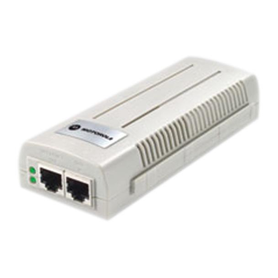
The Power Injector is a small lightweight unit with a RJ-45 Ethernet cord input connector from
the hub on the front right-hand side of the unit and a RJ-45 data and power output connector
to the AP on the front left-hand side of the unit. On the back of the unit is a 110-220 VAC power
input.
A separate Power Injector is required for each device comprising the network. The Power
Injector supports the following devices; AP100, AP200, AP300 and AP-5131.
Caution - Using the Power Injector with an unsupported Motorola device could
render the device inoperable and void your warranty.
The Power Injector has the following features:
• Independent power controller (SPEAR™), CPU controller and input (Data) and output
(Data + Power) shielded RJ-45 connectors
• Supports standard 10/100BaseT Ethernet networks over a standard TIA/EIA-568
Category 5 (or higher) cabling
• Meets the IEEE 802.3af standard
• Universal AC Input: 110/220 V, 60/50 Hz.
• Minimum port output continuous allowable power of 15.4W at 48V
(minimum 12.95W at the PDTE)
• Underload, overload, short-circuit & under/over voltage port protection.
• Port Status and Main power LED indicators
• Standalone or wall mount installation support
• Interconnection option with other Power Injector units.
(4)
Technical Specifications
Physical Specifications
Width
58.5mm
Height
31mm
Depth
145mm
Weight
450gr
Environmental Specifications
Operating Temperature
0°C to 40°C (32°F to 104°F)
Storage Temperature
-20°C to 70°C (-4°F to 158°F)
Operating Humidity
10% to 93% Non-condensing
Storage Humidity
10% to 93% Non-condensing
Electrical Specifications
Input Voltage
90VAC to 264VAC (47Hz - 63Hz)
Maximum Output Power
.15.4 W
Nominal Output Voltage
48VDC
Ethernet Interface
Input (Data In)
Ethernet 10/100Base-T
(RJ-45 female socket)
Output (Data & Power Out)
Ethernet 10/100Base-T, plus 48VDC
RJ-45 female socket, with DC voltage
on pairs 7-8 and 4-5
(5)
Installation
Preparing for Site Installation
The Power Injector can be installed free standing, on an even horizontal surface or wall
mounted using the power injector's wall mounting key holes.
The following guidelines should be adhered to before cabling the Power Injector to the Ethernet
source and Motorola device:
• Verify the device receiving converged power and Ethernet from the Power Injector is a
product approved by Motorola (AP100, AP200, AP300 and AP-5131).
• Do not block or cover airflow to the Power Injector.
• Keep the Power Injector away from excessive heat, humidity, vibration and dust.
• The Power Injector is not a repeater, and does not amplify the Ethernet data signal. For
optimal performance, ensure the Power Injector is placed as close as possible to the
network data port. Do not configure the cable length between the Ethernet network
source, the Power Injector and the Motorola AP beyond 100 meters (333ft).
Cabling the Power Injector
To install the Power Injector to an Ethernet data source and Motorola device:
Caution - Ensure AC power is supplied to the Power Injector using an AC cable with an
appropriate ground connection approved for the country of operation.
1. Connect the Power Injector to an AC outlet (110VAC to 220VAC).
2. Connect RJ-45 Ethernet cable between the network data supply (host) and the Power
Injector Data In connector.
3. Connect a RJ-45 Ethernet cable between the Power Injector Data & Power Out connector
and the Motorola device receiving converged power and Ethernet.
(6)
Advertisement

Related Manuals for Motorola AP-PSBIAS-1P2-AFR


Summary of Contents for Motorola AP-PSBIAS-1P2-AFR
- Page 1 The Power Injector can be installed free standing, on an even horizontal surface or wall contractor to install power drops at each access point location. With the Motorola Power A separate Power Injector is required for each device comprising the network. The Power...
- Page 2 Cable each device as described in the Cabling the Power Injector section of this document. Only one Motorola device (AP 100, AP 200, AP 300 or AP-5131) can be powered from a single Power Injector.