Table of Contents
Advertisement
Advertisement
Table of Contents
Troubleshooting

Related Manuals for Yamaha RT100M


Summary of Contents for Yamaha RT100M
- Page 1 OWNER’S MANUAL RT100M 3UL-28199-26...
- Page 2 INTRODUCTION EAU00000 Congratulations on your purchase of the Yamaha RT100. This model is the result of YamahaÕs vast experience in the production of fine sporting, touring, and pacesetting racing machines. It represents the high degree of craftsmanship and reliability that have made Yamaha a leader in these fields.
-
Page 3: Important Manual Information
This manual should be considered a permanent part of this machine and should remain with it even if the machine is subsequently sold. Yamaha continually seeks advancements in product design and quality. Therefore, while this manual contains the most current product information available at the time of printing, there may be minor discrepancies between your machine and this manual. - Page 4 IMPORTANT MANUAL INFORMATION EW000002 PLEASE READ THIS MANUAL CAREFULLY AND COMPLETELY BEFORE OPERATING THIS MACHINE. EAU00006 THIS MACHINE IS DESIGNED AND MANUFACTURED FOR OFF-ROAD USE ONLY. IT IS ILLE- GAL TO OPERATE THIS MACHINE ON ANY PUBLIC STREET, ROAD OR HIGHWAY. SUCH USE IS PROHIBITED BY LAW.
- Page 5 EAU00008 RT100M OWNERÕS MANUAL © 1999 by Yamaha Motor Co., Ltd. 1st Edition, May 1999 All rights reserved. Any reprinting or unauthorized use without the written permission of Yamaha Motor Co., Ltd. is expressly prohibited. Printed in Japan.
-
Page 6: Table Of Contents
TABLE OF CONTENTS EAU00009 SAFETY INFORMATION........1-1 Seat..............3-6 Safe riding ............1-1 Rear shock absorber adjustment ......3-7 Protective apparel ..........1-2 Modification ............1-2 PRE-OPERATION CHECKS ........ 4-1 Loading and accessories ........1-3 Pre-operation check list ........4-1 Gasoline and exhaust gas........1-4 Location of the important label ......1-5 OPERATION AND IMPORTANT RIDING POINTS .............. - Page 7 TABLE OF CONTENTS Throttle cable free play adjustment ..... 6-9 Rear wheel installation ........6-23 Tires ..............6-10 Troubleshooting..........6-24 Wheels ............... 6-11 Troubleshooting chart ........6-25 Clutch lever free play adjustment ...... 6-12 Front brake lever free play adjustment....6-13 MACHINE CARE AND STORAGE......
-
Page 9: Safety Information
SAFETY INFORMATION EAU00020 TWO-WHEELED MACHINES ARE SINGLE TRACK VEHICLES. THEIR SAFE USE AND OPERATION ARE DEPENDENT UPON THE USE OF PROPER RIDING TECHNIQUES AS WELL AS THE EXPER- TISE OF THE OPERATOR. EVERY OPERATOR SHOULD KNOW THE FOLLOWING REQUIREMENTS BEFORE RIDING. HE OR SHE SHOULD: 1. -
Page 10: Protective Apparel
Always wear protective clothing that covers your legs, ankles, and feet. Modification Modifications made to the machine not approved by Yamaha, or the removal of original equipment, may render your machine unsafe for use and may cause severe personal injury. Modifications may also make... -
Page 11: Loading And Accessories
Genuine Yamaha accessories have been specifically designed for use on this ma- chine. Since Yamaha cannot test all other accessories which may be available, you must personally be re- sponsible for the proper selection, installation and use of non-Yamaha accessories. You should use extreme caution when selecting and installing any accessories. -
Page 12: Gasoline And Exhaust Gas
SAFETY INFORMATION 2. Caution must be used if adding electrical accessories. If these accessories exceed the capacity of the machineÕs electrical system, an electric failure could result, which could cause a dangerous loss of lights or engine power. Gasoline and exhaust gas 1. -
Page 13: Location Of The Important Label
SAFETY INFORMATION EAU01277 Location of the important label Please read the following label carefully before operating this machine. WARNING Before you operate this vehicle, read the ownerÕs manual. English 3HP-21568-00... -
Page 14: Description
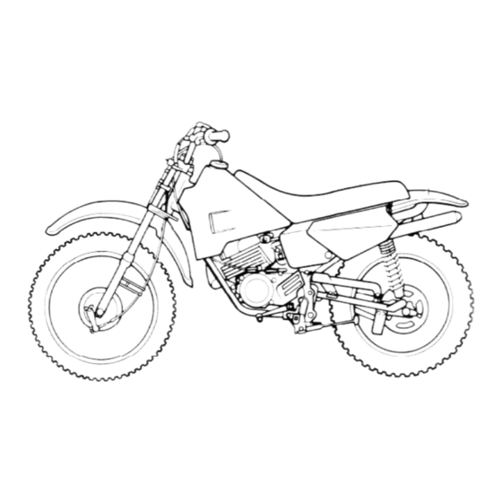
DESCRIPTION EAU00026 Left view Right view 1. Fuel cock (page 3-4) Controls/Instruments 2. Starter (choke) (page 3-5) 3. Air filter (page 6-7) 4. Oil tank (page 3-4) 5. Oil level window (page 3-3) 6. Shift pedal (page 3-1) 7. Seat (page 3-6) 8. -
Page 15: Instrument And Control Functions
INSTRUMENT AND CONTROL FUNCTIONS EAU00027 1. Engine stop switch ÒENGINE STOPÓ 1. Clutch lever 1. Shift pedal EAU00118* EAU00155 EAU00157 Handlebar switch Clutch lever Shift pedal The clutch lever is located on the left This machine is equipped with a con- handlebar. -
Page 16: Front Brake Lever
INSTRUMENT AND CONTROL FUNCTIONS 1. Front brake lever 1. Rear brake pedal 1. Fuel tank cap 2. Open EAU00158 EAU00162 Front brake lever Rear brake pedal EAU00179 Fuel tank cap The front brake lever is located on the The rear brake pedal is on the right Remove the fuel tank cap by turning it right handlebar. -
Page 17: Fuel
INSTRUMENT AND CONTROL FUNCTIONS EAU00185 CAUTION: Always wipe off spilled fuel immedi- ately with a dry and clean soft cloth. Fuel may deteriorate painted surfac- es or plastic parts. EAU00192 1. Filler tube 1. Oil level window Recommended fuel: 2. Fuel level EAU02956 Regular gasoline Two-stroke engine oil... -
Page 18: Fuel Cock
INSTRUMENT AND CONTROL FUNCTIONS 1. Oil tank filler cap 1. Arrow mark positioned over ÒOFFÓ 1. Arrow mark positioned over ÒONÓ EAU01121 Recommended oil: Fuel cock With the lever in this position, fuel flows Yamalube 2 or 2-stroke engine oil The fuel cock supplies fuel from the to the carburetor. -
Page 19: Starter (Choke)
INSTRUMENT AND CONTROL FUNCTIONS 1. Arrow mark positioned over ÒRESÓ 1. Starter (choke) 1. Kick starter EAU00211 EAU00212 Starter (choke) Kick starter This indicates reserve. If you run out of Starting a cold engine requires a richer Rotate the kick starter away from the fuel while riding, move the lever to this air-fuel mixture. -
Page 20: Seat
INSTRUMENT AND CONTROL FUNCTIONS 1. Open To lock the seat EAU02991 Seat Install the seat in its original position. To open the seat NOTE: Turn the lever as shown. Make sure that the seat is securely fit- ted. -
Page 21: Rear Shock Absorber Adjustment
INSTRUMENT AND CONTROL FUNCTIONS EW000040 Always adjust each shock absorber to the same setting. Uneven adjust- ment can cause poor handling and loss of stability. 1. Position indicator EAU00300 Rear shock absorber adjustment Each shock absorber is equipped with a spring preload adjusting ring. Adjust spring preload as follows. -
Page 22: Pre-Operation Checks
PRE-OPERATION CHECKS EAU01114 Owners are personally responsible for their vehicleÕs condition. Your machineÕs vital functions can start to deteriorate quickly and unexpectedly, even if it remains unused (for instance, if it is exposed to the elements). Any damage, fluid leak or loss of tire pressure could have serious consequences. - Page 23 PRE-OPERATION CHECKS ITEM ROUTINE PAGE Brake and clutch lever ¥ Check for smooth operation. 6-18 pivots ¥ Lubricate if necessary. ¥ Check for smooth operation. Sidestand pivot 6-18 ¥ Lubricate if necessary. ¥ Check the tightness of all chassis nuts, bolts and screws. Chassis fasteners Ð...
-
Page 24: Operation And Important Riding Points
OPERATION AND IMPORTANT RIDING POINTS EAU00372 EAU00374 EAU02992 EAU01258 Starting and warming up a Starting a warm engine cold engine The starter (choke) is not required This model is designed for off- when the engine is warm. 1. Turn the fuel cock to ÒONÓ. road use only. -
Page 25: Shifting
OPERATION AND IMPORTANT RIDING POINTS EC000048 EAU00437 Engine break-in CAUTION: There is never a more important period Do not coast for long periods in the life of your machine than the pe- with the engine off, and do not riod between zero and 20 hours of tow the machine a long dis- riding. -
Page 26: Parking
After break-in Avoid prolonged full-throttle operation. Vary speed occasionally. EC000049 CAUTION: If any engine trouble should occur during the break-in period, consult a Yamaha dealer immediately. -
Page 27: Periodic Maintenance And Minor Repair
If you do not have necessary tools re- the safest and most efficient condition quired during a service operation, take possible. Safety is an obligation of the your machine to a Yamaha dealer for service. machine owner. The maintenance and lubrication schedule chart should be... -
Page 28: Periodic Maintenance And Lubrication
PERIODIC MAINTENANCE AND MINOR REPAIR EAU00473 PERIODIC MAINTENANCE AND LUBRICATION EVERY INITIAL ITEM CHECKS AND MAINTENANCE JOBS (1 month) 6 months 12 months ¥ Check fuel hoses for cracks or damage. Fuel line ¥ Replace if necessary. ¥ Check condition. Fuel filter ¥... - Page 29 Transmission oil ¥ Correct accordingly. ¥ Change oil at initial and thereafter every 24 months. * Since these items require special tools, data and technical skills, they should be serviced by a Yamaha dealer. EAU00479 NOTE: The air filter needs more frequent service if you are riding in unusually wet or dusty areas.
-
Page 30: Panel Removal And Installation
PERIODIC MAINTENANCE AND MINOR REPAIR 1. Panel A 1. Panel A 2. Screw EAU01777 Panel removal and installation EAU03021 Panel A The panel illustrated needs to be re- To remove moved to perform some of the mainte- 1. Remove the seat. (See page 3-6 nance described in this chapter. -
Page 31: Spark Plug Inspection
Instead, take the machine to a Yamaha dealer. The spark plug should Tightening torque: be periodically removed and inspected Spark plug: because heat and deposits will cause 25 Nm (2.5 mákg) -
Page 32: Transmission Oil
PERIODIC MAINTENANCE AND MINOR REPAIR 2. With the engine stopped, unscrew the dipstick and rest it on the threads of the oil filler hole. NOTE: Wait a few minutes until the oil level settles before checking. 3. The oil level should be between the maximum and minimum level 1. -
Page 33: Air Filter
PERIODIC MAINTENANCE AND MINOR REPAIR 5. Fill the engine with oil. Install the dipstick and tighten it. Recommended oil: See page 8-1. Oil quantity: Total amount: 0.7 L Periodic oil change: 1. Screw 1. Air filter element 0.65 L 3. Remove the air filter element from EAU02995 Air filter its case and clean it with solvent. -
Page 34: Carburetor Adjustment
EC000085 adjustment. Most adjustments should CAUTION: be left to a Yamaha dealer who has the professional knowledge and experi- Make sure the air filter is prop- ence to do so. However, the following erly seated in the filter case. -
Page 35: Idle Speed Adjustment
Standard idle speed: 1,300 ~ 1,450 r/min NOTE: If the specified idle speed cannot be obtained by performing the above ad- justment, consult a Yamaha dealer. -
Page 36: Tires
Front Rear 3. Tighten the locknut. in it, or if the side wall is cracked, con- 125 kPa 125 kPa tact a Yamaha dealer immediately and Off-road riding (1.25 kgf/cm (1.25 kgf/cm 1.25 bar) 1.25 bar) have the tire replaced. -
Page 37: Wheels
Brakes, tires, and warpage of the wheel. Be sure the related wheel parts replacement Minimum tire tread spokes are tight and undamaged. should also be left to a Yamaha 1.0 mm depth (front and rear) If any abnormal condition exists in dealer. -
Page 38: Clutch Lever Free Play Adjustment
PERIODIC MAINTENANCE AND MINOR REPAIR If the specified free play cannot be ob- tained, proceed with the following steps. 4. Loosen the locknut 1. 5. Turn the adjusting bolt 2 in direction a to loosen the cable. 6. Loosen the locknut 3. 7. -
Page 39: Front Brake Lever Free Play Adjustment
PERIODIC MAINTENANCE AND MINOR REPAIR 1. Locknut 1. Adjusting nut a. Free play 2. Adjusting bolt If the specified free play cannot be ob- EAU01510* c. Free play Rear brake pedal free play tained, proceed with the following EAU01472 adjustment steps. -
Page 40: Checking The Front And Rear Brake Shoes
If the thickness is less than EW000102 Spin the wheel several times and find 2 mm, have a Yamaha dealer replace the tightest position of the chain. Check the shoes as a set. Brake pedal free play should be and/or adjust the chain slack while itÕs... -
Page 41: Drive Chain Slack Adjustment
PERIODIC MAINTENANCE AND MINOR REPAIR are marks on each side of the swingarm and a match mark on each chain puller. Use these marks to align the rear wheel. EC000096 CAUTION: Too little chain slack will overload the engine and other vital parts. Keep the slack within the specified 1. -
Page 42: Drive Chain Lubrication
Yamaha dealer to replace it. chain lubricant between both rows pin hole do not match, tighten the of side plates and on all center roll- nut slightly to align them. -
Page 43: Throttle Cable And Grip Lubrication
Lubricate the pivoting parts. adjustment. Adjusting should be left to be greased at the time that the cable is Recommended lubricant: a Yamaha dealer who has the profes- lubricated, since the grip must be re- Engine oil sional knowledge and experience to do moved to get at the end of the throttle cable. -
Page 44: Brake And Clutch Lever Lubrication
Lubricate the pivoting parts. Recommended lubricant: Check that the sidestand moves up Lithium soap base grease Recommended lubricant: and down smoothly. Engine oil Recommended lubricant: Engine oil EW000113 If the sidestand does not move smoothly, consult a Yamaha dealer. 6-18... -
Page 45: Front Fork Inspection
If EC000098 any free play can be felt, ask a Yamaha CAUTION: dealer to inspect and adjust the steer- ing. Inspection is easier if the front If any damage or unsmooth move- wheel is removed. -
Page 46: Wheel Bearings
Rear wheel service Use a machine stand or machine jack If there is play in the front or rear wheel Since the Yamaha RT100 has no cen- to elevate the machine so the rear hub or if the wheel does not turn terstand, follow these precautions wheel is off the ground. -
Page 47: Front Wheel Removal
EW000122 over the stopper on the front outer tube) and let the machine down. It is advisable to have a Yamaha 3. Push down hard on the handle- dealer service the wheel. bars several times to check for Securely support the machine proper fork operation. -
Page 48: Rear Wheel Removal
EW000122 brake cam lever. 3. Loosen the wheel axle nut. It is advisable to have a Yamaha 4. Elevate the rear wheel by placing dealer service the wheel. a suitable stand under the engine. -
Page 49: Rear Wheel Installation
PERIODIC MAINTENANCE AND MINOR REPAIR EAU01686* Rear wheel installation 5. Adjust the rear brake pedal free play. (See page 6-13.) 1. Install the rear wheel and the axle. 2. Install the axle nut and let the ma- chine down. 3. Insert the brake rod into the brake cam lever and install the brake free play adjusting nut. -
Page 50: Troubleshooting
If your machine requires any repair, bring it to a Yamaha dealer. The skilled technicians at a Yamaha dealership have the tools, experience, and know- how to properly service your machine. -
Page 51: Troubleshooting Chart
Open throttle half-way and start Wipe clean with dry cloth and correct Wet. spark gap or replace spark plug. the engine. Remove spark plug and check electrodes. Engine doesnÕt start, ask a Dry. Ask a Yamaha dealer to inspect. Yamaha dealer to inspect. 6-25... -
Page 52: Machine Care And Storage
MACHINE CARE AND STORAGE EAU01518* Care Before cleaning Cleaning 1. Cover up the muffler outlet with a After normal use The exposure of its technology makes plastic bag. Remove dirt with warm water, a neutral a machine charming but also vulnera- 2. - Page 53 MACHINE CARE AND STORAGE ECA00010 Do not use any harsh chemical For machines equipped with a CAUTION: products on plastic parts. Be windshield: Do not use strong Avoid using strong acidic wheel sure to avoid using cloths or cleaners or hard sponges as cleaners, especially on spoked sponges which have been in they will cause dulling or...
- Page 54 7. Wax all painted surfaces. 8. Let the machine dry completely NOTE: before storing it or covering it. Consult a Yamaha dealer for advice on what products to use.
-
Page 55: Storage
MACHINE CARE AND STORAGE Storage Long-term c. Install the spark plug cap onto the Before storing your machine for several spark plug and place the spark Short-term months: plug on the cylinder head so that Always store your machine in a cool, 1. - Page 56 MACHINE CARE AND STORAGE 7. Check and, if necessary, correct the tire air pressure, then raise the machine so that both of its wheels are off the ground. Alternatively, turn the wheels a little every month in order to prevent the tires from becoming degraded in one spot.
-
Page 57: Specifications
1.5 L Bore Stroke 52.0 45.6 mm Carburetor Compression ratio 6.7:1 Type quantity VM22SS Starting system Kick starter Manufacturer MIKUNI Lubrication system Separate lubrication Spark plug (Yamaha Autolube) Type/Manufacturer BR7ES / NGK 0.7 ~ 0.8 mm Clutch type Wet, multiple-disc... - Page 58 SPECIFICATIONS Transmission Rear Primary reduction system Helical gear Type With tube Primary reduction ratio 3.895 Size 3.00-16 4PR Secondary reduction system Chain drive Manufacturer/ model CHENG SHIN/KNOBBY Secondary reduction ratio 3.429 Air pressure (cold tire) Transmission type Constant mesh 5-speed Off-road riding Operation Left foot operation...
- Page 59 SPECIFICATIONS Suspension Front Type Telescopic fork Rear Type Swingarm Shock absorbers Front Coil spring / oil damper Rear Coil spring / oil damper Spring preload adjustable Wheel travel Front 110 mm Rear 80 mm Electrical system Ignition system C.D.I. Generator system C.D.I.
-
Page 60: How To Use The Conversion Table
SPECIFICATIONS EAU01064 HOW TO USE THE CONVERSION TABLE CONVERSION TABLE All specification data in this manual are listed in SI and METRIC TO IMPERIAL METRIC UNITS. Metric unit Multiplier Imperial unit Use this table to convert METRIC unit data to IMPERIAL mákg 7.233 ftálb... -
Page 61: Consumer Information
Record this number in the space pro- removal procedures.) Record the infor- vided. mation on this label in the space pro- vided. This information will be needed VEHICLE IDENTIFICATION to order spare parts from your Yamaha NUMBER: dealer. MODEL LABEL INFORMATION:... -
Page 62: Noise Regulation (For Australia)
CONSUMER INFORMATION EAU01388 NOISE REGULATION (For Australia) TAMPERING WITH NOISE CON- TROL SYSTEM PROHIBITED Owners are warned that the law may prohibit: (a) The removal or rendering inopera- tive by any person other than for purposes of maintenance, repair or replacement, of any device or element of design incorporated into any new vehicle for the pur- pose of noise control prior to its... - Page 63 YAMAHA MOTOR CO., LTD. PRINTED ON RECYCLED PAPER PRINTED IN JAPAN 99 · 5 - 0.3 × 1...