Honeywell JADE W7220 Installation Instructions Manual
Economizer module
Hide thumbs
Also See for JADE W7220:
- Installation instructions and operators manual (32 pages) ,
- Installation instructions manual (25 pages) ,
- Manual (24 pages)
Advertisement
Quick Links
JADE™ Economizer Module
(MODEL W7220)
This document describes wiring, power up, basic
troubleshooting, and common installation issues for the
JADE™ Economizer Module (Model W7220). For further
information on mounting and operation, refer to Honeywell
document 63-2700.
BEFORE INSTALLATION
Review the following before installing the The W7220:
Electrical
Rated Voltage: 20 to 30 Vac RMS; 50/60 Hz
Relay Contact Rating: 30 Vac
IMPORTANT
All inputs and outputs must be Class 2 wiring.
INSTALLATION INSTRUCTIONS
Inputs
A Mixed air (MA) analog sensor is required on all W7220
units; either an OA (Outdoor Air) sensor for dry bulb change
over or an OA Sylkbus sensor for outdoor enthalpy change
over is required in addition to the MA sensor. An additional
Return Air (RA) Sylkbus sensor can be added to the system
for differential enthalpy changeover.
DCV (CO
) Sensor (C7232): 2-10 Vdc control signal; mini-
2
mum impedance >50k ohm.
Outputs
Actuator signal: 2-10 Vdc; minimum actuator impedance is
2k ohm
Exhaust fan and AUX: Contact closure (24 Vac)
24 Vac Out: 100 VA Class 2 transformer
When Installing This Product
1. Read these instructions carefully. Failure to follow them
could damage the product or cause a hazardous condi-
tion.
2. Check ratings given in instructions and on the product to
ensure the product is suitable for your application.
3. Installer must be a trained, experienced service
technician.
4. After installation is complete, check out product
operation as provided in these instructions.
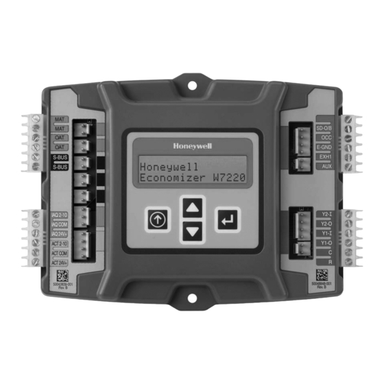
INSTALLATION AND SETUP
The Economizer module may be mounted in any orientation.
However, mounting in the orientation shown above permits
proper viewing of the LCD display and use of the keypad.
E4436
62-0331-03
Advertisement

Related Manuals for Honeywell JADE W7220


Summary of Contents for Honeywell JADE W7220
-
Page 1: Before Installation
JADE™ Economizer Module (Model W7220). For further When Installing This Product information on mounting and operation, refer to Honeywell document 63-2700. 1. Read these instructions carefully. Failure to follow them could damage the product or cause a hazardous condi- tion. - Page 2 JADE™ ECONOMIZER MODULE WIRING CAUTION Equipment Damage Hazard. All wiring must comply with applicable electrical codes and Electrostatic discharge can short equipment ordinances, or as specified on installation wiring diagrams. circuitry. Module wiring in the field is terminated to the four screw Ensure that you are properly grounded before terminal blocks located on the left and right sides.
- Page 3 NOTE THAT THE C7250 20K NTC SENSOR CAN BE MOUNTED IN THE OAT ONLY IN THIS CONFIGURATION. THERMOSTAT IF THE COMMUNICATING ACTUATOR IS USED, IT IS CONNECTED TO THE S-BUS TERMINALS USING M32284 2-WIRE SYLKBUS WIRING. Fig. 2. Stand-alone dry-bulb Economizer configuration with Honeywell MS7503 Direct Coupled Actuator. 62-0331—03...
- Page 4 IF THE COMMUNICATING ACTUATOR IS USED, IT IS CONNECTED TO THE S-BUS DISCHARGE AIR TERMINALS USING 2-WIRE SYLKBUS WIRING. TEMP/HUMIDITY (ENTHALPY) SYLKBUS SENSOR M28979 Fig. 3. Economizer with Sylk Bus sensors for enthalpy configuration with Honeywell M7215 black motor. 62-0331—03...
- Page 5 IF THE COMMUNICATING ACTUATOR IS USED, IT IS CONNECTED TO THE S-BUS DISCHARGE AIR TERMINALS USING 2-WIRE SYLKBUS WIRING. TEMP/HUMIDITY (ENTHALPY) SYLKBUS SENSOR M32285 Fig. 4. Economizer with Sylk Bus sensors for enthalpy configuration with a Honeywell MS7305 Direct Coupled Actuator. 62-0331—03...
-
Page 6: Troubleshooting
ALARMS(_) MA T SENS ERR Initial Menu Display CO2 SENS ERR On initial start up, Honeywell displays on the first line and OA T SENS ERR Economizer W7220 on the second line. After a brief pause, DA ENTHL ERR the revision of the software appears on the first line and the second line will be blank. -
Page 7: Common Installation Issues And Concerns
Wiring I have 4 terminals on my The economizer 24 Vac COM can be wired to the Honeywell actuator common actuator and the wiring only or TR1). The actuators have internal ground circuits. - Page 8 Automation and Control Solutions Honeywell International Inc. 1985 Douglas Drive North Golden Valley, MN 55422 Honeywell Limited-Honeywell Limitée 35 Dynamic Drive ® U.S. Registered Trademark Toronto, Ontario M1V 4Z9 © 2010 Honeywell International Inc. 62-0331—03 M.S. 11-10 customer.honeywell.com Printed in U.S.A.