Honeywell VisionPRO 8000 Product Data
With wi-fi
Hide thumbs
Also See for VisionPRO 8000:
- User manual (156 pages) ,
- Owner's manual (41 pages) ,
- Product data (40 pages)
Table of Contents
Advertisement
VisionPRO
APPLICATION
The VisionPRO® 8000 with Wi-Fi features an effortless, 7-Day
programmable touchscreen thermostat that provides control
of temperature and one of the following: humidification,
dehumidification, or ventilation. Up to 3 Heat/2 Cool heat
pump systems or up to 2 Heat/2 Cool conventional systems
are supported in residential and commercial applications.
®
8000 with Wi-Fi
FEATURES
• Thermostat aquires weather data through either a
wired sensor or an Internet connection, making for a
truly universal installation.
• U1 Terminals
One set of universal outputs that are configurable for one
IAQ product, such as a Humidifier, Dehumidifier or
Ventilator.
• Thermostat S1, S1
Configurable S1 Terminals can be configured for a wired
indoor, wired outdoor, or discharge air sensor.
• On-board Humidity sensor
• Customizable Service Reminders
Set up to 10 service reminders. Choose from the pre-set
options or customize your own. Reminders can be based
on date or the outdoor temperature.
• Selectable for Residential and Light Commercial
Applications
One thermostat does it all to meet the needs of Residential
and Light Commercial applications. Simply select Residen-
tial or Commercial during the installer setup. If Commercial
is selected, the thermostat will use commercial language,
meet building codes and offer 365 day holiday scheduling.
®
PRODUCT DATA
33-00096-01
Advertisement
Table of Contents

Related Manuals for Honeywell VisionPRO 8000


Summary of Contents for Honeywell VisionPRO 8000
-
Page 1: Application
® ® VisionPRO 8000 with Wi-Fi PRODUCT DATA FEATURES • Thermostat aquires weather data through either a wired sensor or an Internet connection, making for a truly universal installation. • U1 Terminals One set of universal outputs that are configurable for one IAQ product, such as a Humidifier, Dehumidifier or Ventilator. -
Page 2: Table Of Contents
TRADELINE® Catalog or price sheets for complete ordering number. If you have additional questions, need further information, or would like to comment on our products or services, please write or phone: 1. Your local Honeywell Environmental and Combustion Controls Sales Office (check white pages of your phone directory). 2. Honeywell Customer Care... -
Page 3: Specifications
® ® VISIONPRO 8000 WITH WI-FI SPECIFICATIONS Cool Indication: ® VisionPRO® 8000 with Wi-Fi displays “Cool On” when the thermostat turns the cooling on. Thermostat Description: Heat Indication: Feature Description VisionPRO® 8000 with Wi-Fi displays “Heat On” when the Powering method •... - Page 4 ® ® VISIONPRO 8000 WITH WI-FI Accessories Product Part Number Wired Outdoor Sensor 10k ohm NTC C7089U1006 Wired Wall-mount Indoor Sensor 10k ohm NTC C7189U1005 Wired Flush-mount Indoor Sensor 20k ohm NTC C7772A1004, C7772A1012 Wired Wall-mount Indoor Sensor 20k ohm NTC TR21 Wired Wall-mount Indoor Sensor 10k ohm NTC TR21-A...
-
Page 5: System Installation
® ® VISIONPRO 8000 WITH WI-FI SYSTEM INSTALLATION When Installing this Product... 1. Read these instructions carefully. Failure to follow the instructions can damage the product or cause a hazard- ous condition. 2. Check the ratings given in the instructions to make sure the product is suitable for your application. -
Page 6: Wiring 24 Vac Common
® ® VISIONPRO 8000 WITH WI-FI INSTALLATION Selecting Discharge Air Temperature Sensor Mounting Location 1. Install the Discharge Air Temperature Sensor on the duct in a location where the air is mixed well. See Fig. 3–7. Model Numbering TH8321 Stages 3H/2C HP 2H/2C CONV Residential or Commercial... - Page 7 ® ® VISIONPRO 8000 WITH WI-FI ALTERNATE MOUNTING LOCATION FOR DISCHARGE SENSOR. MOUNT DISCHARGE BYPASS SENSOR HERE HUMIDIFIER VENTILATOR DEHUMIDIFIER DEHUMIDIFIER MOUNT DISCHARGE SENSOR HERE ABOVE CENTER HEAT OF A-COIL EXCHANGER UPSTREAM OF DEHUMIDIFIER HEAT EXCHANGER BLOWER M35772 BLOWER Fig. 7. M35770 Installing Discharge Air Temperature Fig.
-
Page 8: Selecting Thermostat Location
® ® VISIONPRO 8000 WITH WI-FI Selecting Thermostat Location 2. Position and level the wallplate (for appearance only). 3. Use a pencil to mark the mounting holes. Install the thermostat about 5 ft. (1.5m) above the floor in an area 4. - Page 9 ® ® VISIONPRO 8000 WITH WI-FI Mounting Thermostat on Wallplate CONVENTIONAL 1. Align thermostat at bottom and snap into place as shown. HEAT PUMP Fig. 13. Thermostat wired directly to equipment. 1. Power the thermostat using Rc and C terminals. Refer to Fig.
-
Page 10: Make Changes To Installer Setup
Reset To Select RESET TO DEFAULTS to place all Defaults thermostat settings back to the factory settings. Device Info For Honeywell use only. M35344 Make Changes to Installer Setup RoHs Compliant Conformité RoHs 1. Touch Menu. Assembled in Mexico Assemblé... -
Page 11: Installer Setup (Isu) Table
® ® VISIONPRO 8000 WITH WI-FI Table 2. Installer Setup (ISU) Table. Residential, Installer Setup Commercial Number Name Settings Default or Both Notes Application Residential Residential Both Commercial Thermostat Name [Select Thermostat Name] Thermostat Both The Web Interface displays the name of the thermostat that you enter on this screen. - Page 12 ® ® VISIONPRO 8000 WITH WI-FI Table 2. Installer Setup (ISU) Table. (Continued) Residential, Installer Setup Commercial Number Name Settings Default or Both Notes Cool Stages / 1 if ISU 101 is Both Conventional: Compressor Residential Cool Stage 3 is only available if ISU 101 is Stages Commercial.
- Page 13 ® ® VISIONPRO 8000 WITH WI-FI Table 2. Installer Setup (ISU) Table. (Continued) Residential, Installer Setup Commercial Number Name Settings Default or Both Notes Backup Heat Stg 2 None Default varies based Both The thermostat supports up to 2 backup heat on previous stages.
- Page 14 ® ® VISIONPRO 8000 WITH WI-FI Table 2. Installer Setup (ISU) Table. (Continued) Residential, Installer Setup Commercial Number Name Settings Default or Both Notes A-L/A Terminal None None Commercial This ISU is only displayed when ISU 101 Application is Commercial. Time Of Day Economizer Note: When the thermostat is setup for...
- Page 15 ® ® VISIONPRO 8000 WITH WI-FI Table 2. Installer Setup (ISU) Table. (Continued) Residential, Installer Setup Commercial Number Name Settings Default or Both Notes Auto Changeover 2° F to 9° F (in 1° F increments) 3° F Both This ISU is only displayed when ISU 300 is set Deadband to Automatic.
- Page 16 ® ® VISIONPRO 8000 WITH WI-FI Table 2. Installer Setup (ISU) Table. (Continued) Residential, Installer Setup Commercial Number Name Settings Default or Both Notes Cool Differential Comfort Comfort Both ISU 301 Control Options must be set to Stage 2 Advanced to view or adjust this ISU. 1.0°...
- Page 17 ® ® VISIONPRO 8000 WITH WI-FI Table 2. Installer Setup (ISU) Table. (Continued) Residential, Installer Setup Commercial Number Name Settings Default or Both Notes Heat Differential Comfort Comfort Both ISU 301Temperature Control Options must be Stage 3 set to Advanced to view or adjust this ISU. 1.0°...
- Page 18 ® ® VISIONPRO 8000 WITH WI-FI Table 2. Installer Setup (ISU) Table. (Continued) Residential, Installer Setup Commercial Number Name Settings Default or Both Notes 308, Backup Heat Comfort Comfort Both ISU 301 Control Options must be set to Droop Stage 2 Advanced to view or adjust Backup Heat Droop 2.0°...
- Page 19 ® ® VISIONPRO 8000 WITH WI-FI Table 2. Installer Setup (ISU) Table. (Continued) Residential, Installer Setup Commercial Number Name Settings Default or Both Notes Radiant Cycles 1 to 12 CPH Both This ISU is only displayed when ISU 201 Per Hour Stage 1 Heating Equipment is Geothermal Radiant.
- Page 20 ® ® VISIONPRO 8000 WITH WI-FI Table 2. Installer Setup (ISU) Table. (Continued) Residential, Installer Setup Commercial Number Name Settings Default or Both Notes Heat Cycles Per 1 to 12 CPH Conv. Forced Air = 5 Both This ISU is only displayed when ISU 207 Heat Hour Stage 1 Stages is set to 1 stage.
- Page 21 ® ® VISIONPRO 8000 WITH WI-FI Table 2. Installer Setup (ISU) Table. (Continued) Residential, Installer Setup Commercial Number Name Settings Default or Both Notes Heat Cycles Per 1 to 12 CPH Conv. Forced Air = 5 Both This ISU is only displayed when ISU 207 Heat Hour Stage 3 Stages is set to 3 stages.
- Page 22 ® ® VISIONPRO 8000 WITH WI-FI Table 2. Installer Setup (ISU) Table. (Continued) Residential, Installer Setup Commercial Number Name Settings Default or Both Notes Backup Heat 1 to 12 CPH Electric = Both This ISU is only displayed when ISU 207 or 213 Cycles Per Hour 9 CPH Backup Heat Stages is set to 2 stages.
- Page 23 ® ® VISIONPRO 8000 WITH WI-FI Table 2. Installer Setup (ISU) Table. (Continued) Residential, Installer Setup Commercial Number Name Settings Default or Both Notes Type of Override Standard Standard Commercial Standard: The system maintains temperatures Initiate Occupancy programmed for the occupied and unoccupied time periods.
- Page 24 ® ® VISIONPRO 8000 WITH WI-FI Table 2. Installer Setup (ISU) Table. (Continued) Residential, Installer Setup Commercial Number Name Settings Default or Both Notes Min. Heat 0° F Commercial Off: The heating system will begin recovery at Recovery Outdoor the time that is scheduled. -20°...
- Page 25 ® ® VISIONPRO 8000 WITH WI-FI Table 2. Installer Setup (ISU) Table. (Continued) Residential, Installer Setup Commercial Number Name Settings Default or Both Notes Max. Heat 40° F Commercial Off: The heating system will begin recovery at Recovery Outdoor the time that is scheduled. -20°...
- Page 26 ® ® VISIONPRO 8000 WITH WI-FI Table 2. Installer Setup (ISU) Table. (Continued) Residential, Installer Setup Commercial Number Name Settings Default or Both Notes Min. Cool 90° F Commercial Off: The cooling system will begin recovery at Recovery Outdoor the time that is scheduled. -20°...
- Page 27 ® ® VISIONPRO 8000 WITH WI-FI Table 2. Installer Setup (ISU) Table. (Continued) Residential, Installer Setup Commercial Number Name Settings Default or Both Notes Max. Cool 70° F Commercial Off: The cooling system will begin recovery at Recovery Outdoor the time that is scheduled. -20°...
- Page 28 ® ® VISIONPRO 8000 WITH WI-FI Table 2. Installer Setup (ISU) Table. (Continued) Residential, Installer Setup Commercial Number Name Settings Default or Both Notes Indoor Sensor [Select Indoor Sensor Name] Indoor Sensor Both Select a name (location) of the Wired Remote Name Indoor Sensor.
- Page 29 ® ® VISIONPRO 8000 WITH WI-FI Table 2. Installer Setup (ISU) Table. (Continued) Residential, Installer Setup Commercial Number Name Settings Default or Both Notes Air Filter 2 Both Reminder Run Time: 10, 20, 30, 45, 60, 90, 120, 150 days Calendar: 30, 45, 60, 75 days 3, 4, 5, 6, 9, 12, 15 months...
- Page 30 ® ® VISIONPRO 8000 WITH WI-FI Table 2. Installer Setup (ISU) Table. (Continued) Residential, Installer Setup Commercial Number Name Settings Default or Both Notes User Humidifier in User Humidifier in Heat Mode - User Humidifier in Both Heat: Includes Heat, Emergency Heat and Auto. No or Yes Heat Mode Heat Mode - Yes...
- Page 31 ® ® VISIONPRO 8000 WITH WI-FI Table 2. Installer Setup (ISU) Table. (Continued) Residential, Installer Setup Commercial Number Name Settings Default or Both Notes Dehum Wiring Thermostat defaults Both U1 are dry contacts that require power. See to the unused “Wiring IAQ Equipment or a Heat/Cool Stage to universal terminal the Universal Terminals”...
- Page 32 ® ® VISIONPRO 8000 WITH WI-FI Table 2. Installer Setup (ISU) Table. (Continued) Residential, Installer Setup Commercial Number Name Settings Default or Both Notes User Dehumidifier User Dehumidifier in Heat Mode Use Dehumidifier in Both This ISU is only displayed when ISU 900 Dehum - No or Yes in Heat Mode Cool Mode - Yes...
- Page 33 ® ® VISIONPRO 8000 WITH WI-FI Table 2. Installer Setup (ISU) Table. (Continued) Residential, Installer Setup Commercial Number Name Settings Default or Both Notes Dehumidifier Filter Both Reminder 30, 60, Calendar Days 3 to 12 Calendar Months (in 1 month increments) 1000 Ventilation Type None...
- Page 34 ® ® VISIONPRO 8000 WITH WI-FI Table 2. Installer Setup (ISU) Table. (Continued) Residential, Installer Setup Commercial Number Name Settings Default or Both Notes 1012 Vent Priority Lockouts Lockouts Residential Lockouts are Priority: The thermostat places a priority on lockouts versus the ASHRAE 62.2 ASHRAE ventilation standard.
- Page 35 ® ® VISIONPRO 8000 WITH WI-FI Table 2. Installer Setup (ISU) Table. (Continued) Residential, Installer Setup Commercial Number Name Settings Default or Both Notes 1014 Vent During Hum Both This feature is used to help reach the user's or Dehum Calls desired humidity level by not allowing the ventilation equipment to run during a call for humidification or dehumidification.
- Page 36 ® ® VISIONPRO 8000 WITH WI-FI Table 2. Installer Setup (ISU) Table. (Continued) Residential, Installer Setup Commercial Number Name Settings Default or Both Notes 1402 Indoor -3° F to 3° F (in 1° F increments) 0° F Both 0° F - No difference in displayed temperature Temperature and the actual room temperature.
-
Page 37: Connect To Wi-Fi® Network
NOTE: You will need the thermostat MAC and CRC IDs to M35346 add the thermostat. They are on the screen under Menu, Wi-Fi Setup and on the Thermostat ID Card packed with the thermostat. M35360 Connection Successful M35351 Register at: Honeywell.com/TCC M35361A 33-00096—01... - Page 38 ® ® VISIONPRO 8000 WITH WI-FI ® Connect to a hidden Wi-Fi network 1. Touch MENU, then Wi-Fi Setup. DoaIol Inrol Madorl 2. Touch Other, then Select. Wi-Fi Setup 3. When prompted, press the screen to edit the network Installer Options name.
-
Page 39: Installer Tests
® ® VISIONPRO 8000 WITH WI-FI INSTALLER TESTS Use the installer tests to check out the system: • Equipment Test: Tests the heating, cooling, fan, and IAQ equipment. The test allows you to manually call for each system to ensure the equipment and thermostat operate properly. -
Page 40: Operation
® ® VISIONPRO 8000 WITH WI-FI MOUNTING C7089U1006 WIRED OUTDOOR TEMPERATURE SENSOR Do not mount the sensor: • in direct sunlight. • where hot or cold air blows on the sensor. Discharge line from an outdoor compressor unit, vent or fan causes inaccurate temperature readings. -
Page 41: Setting The Time/Date
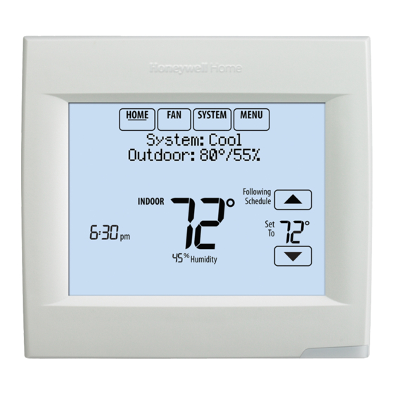
® ® VISIONPRO 8000 WITH WI-FI HOME. Touch to display Home screen. FAN. Select fan mode. SYSTEM. Select system mode (Heat/Cool). MENU. Touch to display options. Start here to set a program schedule. Current status. Shows system mode (heat/cool), outdoor ®... -
Page 42: Setting System Mode
® ® VISIONPRO 8000 WITH WI-FI Preset Energy-Saving Schedules 3. Touch Done to save and exit. • On: Fan is always on. These default Energy Saver settings can reduce expenses. • Auto: Fan runs only when heating or cooling system is •... -
Page 43: Permanent Hold
® ® VISIONPRO 8000 WITH WI-FI Overriding Schedules: Residential NOTE: To reduce costs, use the “Preset Energy-Saving Schedules” on page 42. 3. Select the days to schedule, touch Next. 1. Touch to adjust the temperature (right side of screen) and the Hold Until time (left side). -
Page 44: Viewing Equipment Status
® ® VISIONPRO 8000 WITH WI-FI Setting Vacation Hold: Residential This feature helps you save energy while you are away, and restores comfortable settings just before you return home. 1. Touch MENU. MCR34100 Fig. 48. 2. Select Vacation Mode. MCR34106 Fig. -
Page 45: Holiday Mode
® ® VISIONPRO 8000 WITH WI-FI 1. Touch MENU. 2. Select Create New Event. Create New Event MCR34100 Fig. 52. 2. Select Holiday Schedule. MCR34116 Fig. 56. Holiday Schedule 3. Select Specific Date or Month/Weekday. Holiday Mode • For Specific Date, you are prompted to select the event’s start date, settings, end date, and frequency. - Page 46 ® ® VISIONPRO 8000 WITH WI-FI 1. Touch MENU. Add / Edit Holidays MCR34100 Fig. 62. 2. Select Holiday Mode to display Temperature While Away. MCR34119 Fig. 59. 3. Touch the check box next to each holiday for which you Holiday Mode want to maintain specific settings, (Touch ...
- Page 47 ® ® VISIONPRO 8000 WITH WI-FI Humidification Press HERE Auto Start Occupancy MCR34129 Fig. 68. M34127 3. Touch to select humidity level. Fig. 65. 4. Touch Done to save your settings. Touch Cancel to ignore changes. Touch the buttons to set the temperature or the Hold ...
- Page 48 ® ® VISIONPRO 8000 WITH WI-FI 1. Touch MENU and select Dehumidification. Dehumidification MCR34100 Auto Fig. 70. Dehumidification Equipment Status MCR34130 MCR34131 Fig. 71. Fig. 72. 2. Select Auto. 3. Touch to select humidity level. 4. Touch Done to save your settings. Touch Cancel to ignore changes.
- Page 49 ® ® VISIONPRO 8000 WITH WI-FI Adjusting Dehumidification Settings: Adjusting Ventilation Settings Commercial Use 1. Touch MENU, and select Ventilation. This feature can control a dehumidifier or use your air conditioner to reduce humidity. MCR34100 1. Touch MENU and select Dehumidification. Fig.
-
Page 50: Cleaning The Thermostat Screen
® ® VISIONPRO 8000 WITH WI-FI Temporary Boost: Touch 2. Select an option and follow prompts: to select how long to run ventilation temporarily. To turn it off, set it to zero. • Reminders to change filters • Fahrenheit/Celsius display •... -
Page 51: Adjusting Security Settings
® ® VISIONPRO 8000 WITH WI-FI 3. Touch Yes. A countdown timer displays elapsed time until • Unlocked: Full access allowed. • Partially locked: Only temperature can be changed. the screen is reactivated. • Fully locked: No access allowed. Clean screen Lock Mode for 30 seconds? Unlocked... -
Page 52: Advanced Features
® ® VISIONPRO 8000 WITH WI-FI Advanced Features P + I CONTROL A conventional mechanical or electronic thermostat does not control temperature precisely at setpoint. Typically there is an ADAPTIVE INTELLIGENT RECOVERY (RESIDENTIAL USE offset (droop) in the control point as the system load changes. ONLY) Many factors contribute to offset including the switch Over time, the VisionPRO®... -
Page 53: Staging Control
® ® VISIONPRO 8000 WITH WI-FI Universal Output Options TH8321 Thermostat Only (U1) • Humidification (ISU 803) Installer Options • Dehumidification (ISU 904) • Ventilation (ISU 1002) • Cool Stage 3 (ISU 208) • Conventional Heat Stage 3 (ISU 210, 214) •... - Page 54 ® ® VISIONPRO 8000 WITH WI-FI TO CHANGE DIFFERENTIAL SETTINGS MANUAL TEMPERATURE CHANGE 1. Select Advanced Options to view/adjust differentials When the Backup Heat Droop is set to Comfort, the thermostat between all stages. uses backup heat as needed to keep the indoor temperature within 1 °F (0.5 °C) of the setpoint.
- Page 55 ® ® VISIONPRO 8000 WITH WI-FI Backup Heat Upstage Timer Multistage Control The Backup Heat Upstage Timer is available for any system Multistage Control keeps the high stage of the equipment with 2 heating types and the Backup Heat Droop is set to 2 °F running until the desired setpoint is reached.
-
Page 56: Heat Pump And Backup Heat Operation
® ® VISIONPRO 8000 WITH WI-FI HEAT PUMP AND BACKUP HEAT OPERATION Heat pump with outdoor temperature lockouts Outdoor temperature lockouts are optional. See Installer Setup options (ISU 312). Alert Light - General Forced Air Heat and then Backup Heat as needed to maintain the desired temperature. - Page 57 ® ® VISIONPRO 8000 WITH WI-FI Fossil Fuel Backup Heat (Backup Heat NOT Fig. 110. Other options are "None" (Geothermal Forced Air is not used) and "Cool Only" (Geothermal Forced Air Allowed to Run with Heat Pump) is only used for cooling). See Fig. 110. HEAT MODE The thermostat turns on Backup Heat only when the indoor temperature drops to the selected Backup Heat Droop setting...
-
Page 58: Indoor Air Quality (Iaq) Control
® ® VISIONPRO 8000 WITH WI-FI 6. Select the Backup Heat Type. See Fig. 113. humidity to help prevent frost or condensation on your windows. Use a higher number if indoor air seems too dry. To prevent frost/condensation on your windows during cold outdoor temperatures, poorly insulated windows require a lower Window Protection setting, which will limit how much your humidifier can run. - Page 59 ® ® VISIONPRO 8000 WITH WI-FI 2. Select the terminals wired to the humidifier. See allowed to run again after the discharge tem- Fig. 116. perature rises above the dew point tempera- ture. NOTE: U1 are Normally Open Dry Contacts that require power from the system transformer or a separate transformer.
-
Page 60: Control Humidification Level
® ® VISIONPRO 8000 WITH WI-FI Fig. 124. 6. Window Protection is set on a scale from 1–10. A setting of 1 represents poorly insulated windows and a setting of 10 represents well insulated windows. A lower number Fig. 120. automatically reduces the humidity to help prevent frost or condensation on your windows. -
Page 61: Set Up Dehumidification With Cooling System
® ® VISIONPRO 8000 WITH WI-FI NOTE: The thermostat will not lower the fan speed when the second stage of cooling is on. Set up Dehumidification With Cooling System Some screens shown in this section may not appear on the thermostat, depending on how you set up dehumidification. - Page 62 ® ® VISIONPRO 8000 WITH WI-FI Fig. 131. 2. Select the terminals wired to the Whole House Dehumid- ifier. See Fig. 132. Fig. 133. 4. Set Dehumidifier Fan Control settings. See Fig. 134. • Tstat Controls Fan Thermostat turns on the dehumidifier and the fan when dehumidification is needed.
-
Page 63: Set Up Dehumidification Away Mode
® ® VISIONPRO 8000 WITH WI-FI Dehumidification Away Mode Set up Dehumidification Away Mode 1. Select Allowed at ISU 918. See Fig. 138. Dehumidification Away Mode protects the home when unoccupied for long periods of time during hot and humid weather by maintaining the desired humidity and temperature settings. -
Page 64: Control Dehumidification Level
® ® VISIONPRO 8000 WITH WI-FI Control Dehumidification Level • Low Limit Temperature Setting If the cooling system is used to control humidity while 1. Touch MENU and select Dehumidification. Dehumidification Away Mode is active, the thermostat allows the cooling system to lower the indoor air to the Low Limit Temperature Setting to reach the Dehumidification Setting at ISU 920. -
Page 65: Set Up Dehumidification With Cooling System
® ® VISIONPRO 8000 WITH WI-FI NOTE: Reheat can be used on heat pump applications humidification and dehumidification settings. The thermostat that have a forced air backup heat source (gas, will automatically switch between humidification and oil, or electric). The thermostat will turn on the dehumidification to maintain the desired humidity level. -
Page 66: Set Up Dehumidification With Dehumidifier
® ® VISIONPRO 8000 WITH WI-FI Dehumidification using a Dehumidifier • Normally Closed – contacts are normally closed and will open during a call for dehumidification. The Dehumidifier option requires a dedicated unit for dehumidification. The thermostat can be set to control dehumidification in all modes (Heat, Off, Cool [ISU 912]). -
Page 67: Control Dehumidification Level
® ® VISIONPRO 8000 WITH WI-FI 3. Select the system mode(s) to allow dehumidification. 5. Set the desired lockout option. See Fig. 153. See Fig. 151. NOTE: Heat includes Heat, Emergency Heat and Auto. If the system is in Auto mode, the thermostat will allow dehumidification if the last call was for heat. -
Page 68: Ventilation
® ® VISIONPRO 8000 WITH WI-FI 2. Select Auto. • Percent On Time The thermostat operates ventilation equipment based on a percentage entered in the installer setup (ISU 1012). For example if Percent On Time is set to 50%, the ventilation equipment will run at random times during a 1 hour period Dehumidification until it reaches a 50% run time (approximately 30 minutes). -
Page 69: Set Up Ventilation
® ® VISIONPRO 8000 WITH WI-FI 3. Select the Ventilation Control Method. See “Ventilation Options are: • Ventilation Low Temperature Lockout Setpoint Control Methods (ISU 1005)” on page 68 for more infor- (Off, -20° to 40° F) mation. See Fig. 159. •... - Page 70 ® ® VISIONPRO 8000 WITH WI-FI will indicate the following based on the Equipment Venti- When using this option, it is recommended to lation Rate, Square Footage and Number of Bedrooms. increase the rate (CFM) of the ventilation equipment See Fig. 162. to meet the ASHRAE 62.2 ventilation standard in a •...
- Page 71 ® ® VISIONPRO 8000 WITH WI-FI 8. If Percent On Time was selected for ISU 1005, select the When ISU 1012 Ventilation Priority is set to Lockouts are Ventilation Percent on Time. See Fig. 164. Priority, or ISU 1005 Ventilation Control Methods is set to Percent On Time, the thermostat will indicate whether this meets or may not meet the ASHRAE 62.2 Standard or the Percent On Time setting.
- Page 72 ® ® VISIONPRO 8000 WITH WI-FI 2. Select Mode, Temporary Boost, or Lockout, then select or dehumidification. The thermostat will indicate whether this meets or may not meet the ASHRAE 62.2 Standard appropriate options. or the Percent On Time setting. See Fig. 168. NOTE: ISU 1014 Lockout Ventilation on Humidification or Dehumidification Calls is not an option when Mode...
-
Page 73: Iaq Reminders
® ® VISIONPRO 8000 WITH WI-FI 3. Select the reminder you want to set. 4. Press to set the timer length. Ranges, incre- ments, and units will change based on the reminder. Lockout in Sleep NOTE: When set for run time days, the thermostat Period: tracks the amount of time the fan has run and compares that time against the number of run... - Page 74 ® ® VISIONPRO 8000 WITH WI-FI 4. Press the up or down arrows to set the outdoor tempera- You can change or create custom reminders in ISU 1200. ture and press Next. Fig. 179. Fig. 182. For example, to set up a Fall Service Reminder based on NOTE: A seasonal maintenance reminder will appear Outdoor Temperature: when the outdoor temperature reaches the level...
- Page 75 ® ® VISIONPRO 8000 WITH WI-FI 7. When the user touches Press HERE for info on the 10. To clear the Alert, (and turn off the Red Alert Light on the Home Screen, the reminder message will be displayed. thermostat), select Dismiss. To create a new custom reminder: 1.
- Page 76 ® ® VISIONPRO 8000 WITH WI-FI 5. Touch Press HERE to edit to set the reminder message 8. Select whether you want the reminder to appear only (see Fig. 191). once or to be recurring, and press Next. Fig. 191. Fig.
- Page 77 ® ® VISIONPRO 8000 WITH WI-FI 12. When the user touches Press HERE for info on the • Dismiss Home Screen, the reminder message will be displayed: • View Dealer Info 14. Selecting View More Info displays the Custom Reminder message.
-
Page 78: Commercial Features
® ® VISIONPRO 8000 WITH WI-FI COMMERCIAL FEATURES The thermostat can be setup for residential or light commercial applications (ISU 101). When the thermostat is setup for commercial, the thermostat meets commercial code, Title 24 and provides the following features: •... - Page 79 ® ® VISIONPRO 8000 WITH WI-FI 4. Make selections as prompted on each screen. For more 4. Review the settings and touch Done to save them. Touch information, see next two pages. Cancel to ignore the changes. 5. Touch Done to save your settings. Setting Custom Events: Commercial Schedule adjusted to 62 in heating...
- Page 80 ® ® VISIONPRO 8000 WITH WI-FI 4. Touch to select the Heat and Cool temperatures. Temperature Temperature While Away During Holiday MCR34123 MCR34121 Fig. 214. Fig. 211. 4. Review the settings and touch Done to save them. Touch 5.
-
Page 81: Ramp Rates (Commercial Use)
® ® VISIONPRO 8000 WITH WI-FI Ramp Rates (Commercial Use) system may run several hours when it may not be required to maintain indoor comfort. When outdoor conditions are When the ramp rate is set to Off, the thermostat begins favorable, ventilation with outdoor air can achieve the same recovery at the scheduled time. -
Page 82: Pre-Occupancy Purge
® ® VISIONPRO 8000 WITH WI-FI Fig. 218. Pre-Occupancy Purge Fig. 220. Temperature Display The thermostat can be set up for Pre-Occupancy Purge in the installer setup (ISU 401). When setup for Pre-Occupancy The temperature reading displayed on the home screen is from Purge, the thermostat runs the fan 1 to 3 hours before each the sensor or sensors that are being used for temperature occupied period to provide a comfortable workplace upon... - Page 83 ® ® VISIONPRO 8000 WITH WI-FI Calibration - Outdoor Sensor Table 7. C7089U1006 Sensor Resistance at Outdoor Temperature. (Continued) The C7089U1006 Outdoor Sensor is calibrated at the factory Outdoor Outdoor and cannot be recalibrated in the field. Temperature Temperature Ohms of Ohms of Table 7.
-
Page 84: Wiring
® ® VISIONPRO 8000 WITH WI-FI WIRING Table 9. Thermostat Terminal Designation Descriptions. Conventional System Heat Pump Terminal Description Terminal Description Common wire from secondary side of cooling Common wire from secondary side of cooling transformer (if 2 transformers). transformer. Cooling power Cooling power Heating power... - Page 85 K terminal, split that signal and re-route it to operate the compressor and/or fan for normal operation. See form 69-2065EFS for additional information. THX9321R SUBBASE WIRESAVER CONVENTIONAL USED USED Rc K C W-O/B AUX/E Honeywell THP9045A Rc Y G C W-O/B USED USED USED FURNACE HEAT PUMP M31302A Fig.
-
Page 86: Wiring Iaq Equipment Or A Heat/Cool Stage To The Universal Terminals
® ® VISIONPRO 8000 WITH WI-FI Wiring IAQ Equipment or a Heat/Cool Stage to the Universal Terminals To Thermostat “U” terminals can be used for humidification, dehumidification, ventilation or a stage of heating/cooling. SYSTEM SYSTEM TRANSFORMER TRANSFORMER THERMOSTAT THERMOSTAT HUM, DEHUM OR FIELD INSTALL JUMPER VENT BETWEEN R AND U1... -
Page 87: Wiring C7089U1006 Outdoor Sensor
® ® VISIONPRO 8000 WITH WI-FI Wiring C7089U1006 Outdoor Sensor CAUTION Electrical Shock Hazard. CAUTION Can cause electrical shock or equipment damage. Disconnect power supply before connecting wiring. Electrical Interference (Noise) Hazard. Can cause erratic system operation. Wiring must comply with applicable codes, ordinances and Keep wiring at least one foot away from large inductive regulations: loads such as motors, line starters, lighting ballasts and... -
Page 88: Wiring Guide - Wired Indoor Sensors
® ® VISIONPRO 8000 WITH WI-FI Wiring guide — Wired Indoor Sensors Wiring 2 TR21 sensors (20k ohm) and 1 TR21-A sensor (10k CAUTION ohm) for temperature averaging network. Select 20K in the Installer Setup (ISU 503) when using 2 TR21 sensors and 1 Electrical Interference (Noise) Hazard. -
Page 89: Troubleshooting
® ® VISIONPRO 8000 WITH WI-FI TROUBLESHOOTING Table 10. Troubleshooting. Symptom Action • Check circuit breaker and reset if necessary. Screen is blank • Make sure power switch at heating and cooling system is on. • Make sure furnace door is closed securely. Screen is difficult •... -
Page 90: Regulatory Information
® ® VISIONPRO 8000 WITH WI-FI REGULATORY INFORMATION FCC Compliance Statement IC Regulations This device complies with Industry Canada’s licence-exempt § 15.19 (A)(3) (USA ONLY) RSSs. Operation is subject to the following two conditions: This device complies with part 15 of the FCC Rules. Operation 1. - Page 91 ® ® VISIONPRO 8000 WITH WI-FI 33-00096—01...
- Page 92 Wi-Fi is a registered trademark of Wi-Fi Alliance Automation and Control Solutions Honeywell International Inc. 1985 Douglas Drive North ® U.S. Registered Trademark Golden Valley, MN 55422 © 2016 Honeywell International Inc. 33-00096—01 M.S. 01-16 customer.honeywell.com Printed in United States...