Table of Contents
Advertisement
Available languages
Available languages
Quick Links
EN
DE
EN
Smart card reader with keypad
Mounting the unit
1.
Remove power to the control panel, or 4-door DGP, as applicable.
2.
Remove the two front panel screws at the bottom of the RAS (see
Figure
), and then remove the RAS back plate. Retain the screws
to secure the RAS later.
3.
Position the RAS back plate (with the tamper spring at the top)
against the mounting surface to determine the locations of
mounting holes and for cabling access (a reduced card reading
range may occur if mounted on a metal surface).
4.
Mount the back plate on a flat surface using four screws (the hole
nearest the tamper spring must have a screw in order for the
tamper switch to work correctly).
5.
Terminate the cable, as required (see wiring details below).
6.
For on-line mode, set the BUS address (DIP switches 1 through 4).
For on-line mode, set the TERM switch (DIP switch 5) as required.
For off-line mode, the TERM switch must be off (up). See DIP switch
settings for details.
7.
Mount the RAS on the back plate by engaging the top, and then
lowering the RAS to be flat against the back plate. The rear tamper
switch must be sealed for the system to work correctly. Ensure that
the back plate tamper spring rests on the tamper switch actuator
RAS 1
RAS 2
RAS 3
RAS 4
RAS 5
RAS 6
RAS 7
RAS 8
RAS 9
RAS 10
RAS 11
RAS 12
RAS 13
RAS 14
RAS 15
RAS 16
ATS1197
(protruding from the resin in the back of the RAS) when the RAS is in
position.
8.
Fix the RAS to the back plate using the two screws removed earlier
from the bottom of the RAS.
9.
Apply power to the control panel, or the 4-door DGP.
10. For online mode, use an LCD RAS on the BUS (or the system
management software) to program polling and set up the required
items for the new RAS. In particular, the ATS1197 RAS must be
programmed as a non-LCD RAS.
11. Check that the ATS1197 is communicating correctly and verify that
the tamper switch is working properly (i.e. "RAS Tamper" is not
showing on the LCD RAS).
WARNING:
All power should be turned off to the control panel before wiring
the RAS.
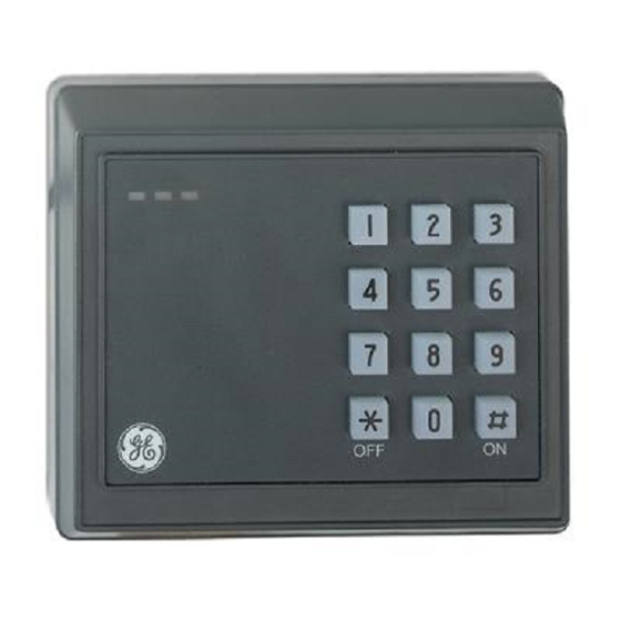
Location of features (figure
1.
Red/Green dual colour LED.
2.
Yellow LED.
3.
Red LED.
4.
Locking screws.
Connecting control panel to keypad RAS
Refer to the ATS Control Panel Installation Guide for instructions.
Tamper switch
The ATS1197 tamper switch is closed when the unit is fitted on the
mounting plate. In operation, the LCD display will show "RAS Tamper"
when not closed.
RAS DIP switch settings (figure
A row of DIP switches is located on the rear of the RAS (figure
used for setting the RAS address and the bus termination (TERM)
condition. These settings are described in the following sections.
1.
RAS address
in "UP" position is off, and switch in "DOWN" position is on.
2.
TERM switch
must be no more than two TERM switches or links set to 'ON' for
any bus. Refer to the control panel installation guide for details
about the use of TERM switches or links.
'ON' is indicated as black (down). Example: RAS 2 = On, off, off, off.
Connections
Colour
Application
Red
+12 V nominal (8.5 to 14.0 VDC supply)
The RAS can be powered using the bus + and – power from
the control panel if the distance between the RAS and the
control panel does not exceed 100 m (328 feet). Otherwise
the RAS can be powered by AUX PWR from a DGP, or by an
auxiliary power supply.
Black
0 V (DC supply ground)
Green
D0/D–/Clock, may be used for D0 (Wiegand data), D–
(RS485 data), Magnetic stripe clock. Normal operating
voltage 0 to +5 V (absolute maximum is +12 V).
2006 GE Security B.V.
All rights reserved.
www.gesecurity.net
Smart card reader with keypad
)
)
: Set the RAS address using switches 1 to 4. Switch
: Use switch 5 to set TERM to 'ON', if needed. There
ATS1197
) and is
MAINST-ATS1197
Mar 2006
Advertisement
Table of Contents

Related Manuals for GE ATS1197


Summary of Contents for GE ATS1197
- Page 1 Tamper switch RAS 1 RAS 2 RAS 3 RAS 4 The ATS1197 tamper switch is closed when the unit is fitted on the mounting plate. In operation, the LCD display will show "RAS Tamper" when not closed. RAS 5 RAS 6...
-
Page 2: Status Led Indications
In offline mode, the TERM switch (DIP switch 5) must be ‘off’ (up). White D1/D+/Data, may be used for D1 (Wiegand data), D+ DIP switches 1 to 4 are not used in offline mode. (RS485 data), magnetic stripe data. Normal operating voltage 0 to +5 V (absolute maximumis +12 V). -
Page 3: Programming Map
7-Watch Dog minute to indicate that the RAS is connected and operating normally. If 0-Exit, Menu: *-Change, #-Exit the ATS1197 tamper is active, the data byte will not be sent (disabled by default). 8-O/C Output Door Output Menu 8, O/C output... -
Page 4: Data Transmission
Unsecured When an unsecured card is badged on a reader using the programmiert werden. magnetic stripe format, 32 bit data is transmitted. 11. Überprüfen Sie, ob das ATS1197 ordnungsgemäß kommuniziert und stellen Sie sicher, dass der Sabotagekontakt richtig arbeitet (die Meldung "BDT-Sabotage" sollte nicht auf der LCD-BDT angezeigt Offline werden). -
Page 5: Fehlerbehebung
"EIN" wird schwarz dargestellt (nach unten). Beispiel: BDT 2 = Ein, Bereiche scharfgeschaltet sind. Rot blinkend während Aus, Aus, Aus. Entriegelungszeit, wenn Bereich scharfgeschaltet ist. Verbindungen LED aus: wenn mindestens eine, aber nicht alle der BDT-Alarmgruppe zugeordneten Bereiche Farbe Anwendung scharfgeschaltet sind. - Page 6 Die Rx- und Tx-LEDs auf der Leiterplatte sollen die Störungsdiagnose Programmieroptionen erleichtern; sie sind sichtbar, wenn die rückwärtige Kunststoffabdeckung entfernt wurde. Das ATS1197 stellt ein Menü zur Verfügung, über das eine Reihe von Die gelbe Rx-LED blinkt, um anzuzeigen, dass abgefragte Daten am Optionen eingestellt werden können. Systembus...
- Page 7 Menü 9, Optionskarte Offline Mit dieser Option wird die Verwendung von Leserkonfigurationskarten Leserprotokoll (optionale Karten) am Leser aktiviert (Standardeinstellung) und Kartenformat Wiegand Magnetstreifen deaktiviert. Diese Option sollte deaktiviert werden, wenn unterbunden werden soll, dass die Lesereinrichtung durch Konfigurationskarten Gesichert Wird die Karte einem Wird die Karte einem Leser verändert werden kann.
-
Page 8: Manufacturer's Declaration Of Conformity
MANUFACTURERS DECLARATION OF CONFORMITY Product identification: Model/type : ATS1197 BOM revision level Category (description) : Non LCD, Remote Arming Station, with Card Reader and keypad Brand : GE Security Manufacturer: GE Security 646 Whitehorse Road Mitcham, 3132 Australia GE Security B.V.