Table of Contents
Advertisement
Available languages
Available languages
Advertisement
Table of Contents

Related Manuals for NAMCO Ridge Racer V Arcade Battle


Summary of Contents for NAMCO Ridge Racer V Arcade Battle
-
Page 1: Operators Manual
RIDGE RACER V OPERATORS MANUAL T IS THE RESPONSIBILITY OF THE OPERATOR TO MAINTAIN CUSTOMER SAFETY AT ALL TIMES AND IT IS IMPERATIVE THAT THE DETAILS SET OUT IN THIS MANUAL ARE FOLLOWED PRECISELY Issue 1 Part No. 90500117... -
Page 2: Table Of Contents
Contents OPERATORS MANUAL ..........................1 GENERAL SAFETY CONSIDERATIONS ....................4 ALLGEMEINE SICHERHEITSHINWEISE ....................6 GENERELLE SIKKERHEDSOVERVEJELSER ..................8 CONSIDERACIONES GENERALES DE SEGURIDAD................10 CONSIGNES GENERALES DE SECURITE .................... 12 ΕΞΕΤΑΣΗ ΓΕΝΙΚΗΣ ΑΣΦΑΛΕΙΑΣ ......................14 CONSIDERAZIONI GENERALI SULLA SICUREZZA ................16 VANLIGE SIKKERHETSTILTAK ....................... - Page 3 8. MAINTENANCE ..........................56 Error Messages .......................... 58 Replacing the CD Rom Drive ..................... 59 Replacing the Steering PCB and/or Fuse ................... 61 Repacing the Amplifier PCB ....................... 62 Replacing the Fluorescent Lamp or Starter................63 Replacing the Gear Shift Assy ....................64 8-6-1 Replacing the Gear Shift Microswitch ..................
-
Page 4: General Safety Considerations
This equipment is for indoor use only and should only be used for the purpose intended. Namco Europe Ltd. bears no responsibility for accidents, injury or damage resulting from unauthorized changes to, or improper use of this equipment. - Page 5 Do not make any alteration to this equipment without prior approval. Doing so could cause unforeseeable danger. Only parts specified by Namco Europe Ltd. should be used when replacing parts. (Including screws) Ensure that the power to the equipment is turned OFF before commencing any maintenance work.
-
Page 6: Allgemeine Sicherheitshinweise
(Suchsysteme), die Weitergabe oder sonstiges Kopieren für den gewerblichen und privaten Gebrauch sind untersagt und bedürfen der vorherigen Genehmigung durch NAMCO EUROPE LIMITED. Die informationen in diesem Handbuch entsprechen den Tatsachen bei Drucklegung. NAMCO EUROPE LIMITED behält sich jedoch das Recht zu Änderungen ohne vorherige Bekanntgabe vor. - Page 7 Es dürfen keierlei Veränderungen ohne vorherige Genehmigung am Gerät vorgenommen werden. Zuwiderhandlungen stellen eine Gefahrenquelle dar. Für die Repartur dürfen nur Originalersatzteile (incl. Schrauben) von NAMCO EUROPE LTD. verwendet werden. Vor Beginn aller Wartungsarbeiten (Fehlersuche, Reparaturen etc.) muß der Netzstecker gezogen werden.
-
Page 8: Generelle Sikkerhedsovervejelser
Denne rnaskine er kun til indendørs brug og bør kun bruges til det beregnede formål. Namco Ltd. bærer intet ansvar for ulykker eller skader som er et resultat af uautoriserede ændringer eller fejlagtig brug af denne rnaskine. - Page 9 Justeringer eller vedligehold af denne maskine bør kun udføres af kvalificeret personale. Skift ikke noget på maskinen uden godkendelse, det kan føre til uforudset fare. Der bør kun bruges dele specificeret af Namco Europe Limited når der skiftes eller repareres dele (inklusiv skruer).
-
Page 10: Consideraciones Generales De Seguridad
NAMCO EUROPE LIMITED. Si bien la información contenida en este manual se da de buena fe y es correcta en el momento de su impresión, NAMCO EUROPE LIMITED se reserva el derecho de hacer cambios y alteraciones sin previo aviso. - Page 11 No realice alteraciones en esta máquina sin aprobación previa. De hacerlo así, pueden causar peligros imprevisibles. Sólo deben usarse las partes especificadas por Namco Europe Ltd. para reparaciones o reemplazos (incluidos los tornillos). Asegúrese de que la máquina está desconectada antes de comenzar cualquier trabajo de mantenimiento (reparaciones, resolución de problemas, etc.)
-
Page 12: Consignes Generales De Securite
Malgré le fait que les informations contenues dans ce manuel soient données de bonne foi et étaient actualisées au moment de leur impression, NAMCO EUROPE LIMITED se réserve le droit de procéder à des changements ou à des modifications sans avis préliminaire. - Page 13 Ne pas apporter de modifications sur cette machine sans autorisation préalable, faute de quoi cela pourrait entraîner un danger. Seules les pièces détachées Namco Europe Ltd. doivent être utilsées pour le remplacement ou la réparation de pièces (y compris les vis) S’assurer que l’interrupteur soit sor OFF avant de commencer tout travail de maintenance (localisation...
-
Page 14: Εξεταση Γενικησ Ασφαλειασ
Καθώς αυτές οι πληροφορίες σε αυτ το εγχειρίδιο έχουν δοθεί με καλή πίστη και ακριβώς την ώρα της τύπωσης , η εταιρεία NAMCO EUROPE LIMITED κρατάει το δικαίωμα να κάνει οποιεσδήποτε αλλαγές χωρίς ειδοποίηση. Τα μηχανήματα έχουν κατασκευαστεί σύμφωνα με τους ρους της Ευρωπαϊκής Κοιν τητας , και έχουν ελεγχθεί σύμφωνα με τους ν μους... - Page 15 ΣΗΜΕΙΩΣΕΙΣ ΓΙΑ ΤΗΝ ΕΓΚΑΤΑΣΤΑΣΗ 2m 20cm or more 30cm or more 30cm or more ΠΟΤΕ να μην αν βει το μηχ νημα ε ν δεν χει ολοκληρωθε η εγκατ σταση. Play zone Για την αποφυγ ηλεκτρικ ν σοκ πρ πει το μηχ νημα να χει γειωθε . Για...
-
Page 16: Considerazioni Generali Sulla Sicurezza
Quest macchina deve essere usata solo in interni e deve essere usata solo per gli scopi per cui è progettata. Namco Europe Ltd non si assume responsabilità per incidenti, ferite o damni risultanti da cambiamenti non autorizzati o da uso improprio della macchina. - Page 17 Quando si rimpiazza o si riparano delle parti (incluse le viti) si possono usare solo parti approvate dalla Namco Europe Ltd. Assicurarsi che la macchina sia SPENTA prima di incominciare qualsiasi lavoro di manutenzione (guasti, riparazioni etc.) Se state per iniziare un lavoro non descritto in questo manuale, contattate il vostro distributore per instruzioni poichè...
-
Page 18: Vanlige Sikkerhetstiltak
NAMCO EUROPE LIMITED. Da informasjonen i denne manualen er gitt i god tru og var korrekt da den ble utgitt, tillegger NAMCO EUROP LIMITED seg retten til å lage forandringer uten varsel. - Page 19 Installasjon, service, justering eller rutine vedlikehold skal bare utføres av kvalifiserte personer. Ikke lag noen forandringer på denne maskinen uten godkjenning. Dette kan medføre uforutsette farer. Bare deler spesifisert av Namco Europe Ltd. skal benyttes ved utskifting eller reparasjon av deler (dette gjelder også skruer).
-
Page 20: Algemene Veiligheidsoverwegingen
Namco Europe Limited. Ofschoon de informatie in deze handleiding in goed vertrouwen is gegeven en nauwkeurig was ten tijde van het drukken, houdt Namco zich het recht voor om veranderingen en aanpassingen te maken zonder bericht. - Page 21 Maak geen veranderingen aan deze machine zonder goedkeuring vooraf. Dit kan onvoorzien gevaar opleveren. Alleen onderdelen die door Namco Europe Ltd. zijn gespecificeerd dienen gebruikt te worden bij het vervangen of repareren van onderdelen (incl. schroeven). Zorg ervoor dat de machine UITgeschakeld is voordat er enig onderhoudswerk wordt verricht (troubleshooting, reparaties etc.)
-
Page 22: Avisos De Perigo
NAMCO EUROPA LIMITADA. A informação contida neste manual foi fornecida de boa fé, sendo rigorosa na altura da sua publicação. A NAMCO EUROPA LIMITADA, reserva-se o direito de proceder a mudanças e alterações sem qualquer aviso prévio. - Page 23 A substituição ou reparação de peças deverá ser feita apenas com peças de origem ou especificadas pela “Namco Europa Ltd.” (incluindo parafusos) Certifique-se que a maquina se encontra desligada sempre que iniciar qualquer tipo de trabalho de manutenção.
-
Page 24: Allmänna Säkerhetsbeaktanden
återvinningssystem, översändas eller på annat sätt kopieras för offentlig eller privat användning, utan tillstånd från NAMCO EUROPE LIMITED. Eftersom informationen i denna manual lämnas ut i god tro och var korrekt när den trycktes, reserverar sig NAMCO EUROPE LIMITED för ändringar. - Page 25 Gör inga ändringar på denna maskin utan ett godkännande i förväg. Detta kan förorsaka oförutsägbar fara. Endast delar som är specificerade av Namco Europe Ltd. ska användas vid utbyten eller reparation av delar (inklusive skruvar). Försäkra dig om att strömmen är avstängd innan underhållsarbete påbörjas (felsökning, reparationer etc.)
-
Page 26: Yleiset Turvallisuunäkökodat
Tästä julkaisusta ei saa ottaa missään muodossa kopioita yksityis- tai julkiseen käyttöön ilman NAMCO EUROPE LIMITED:in lupaa. Tässä ohjekirjassa olevat tiedot pitävät julkaisuhetkellä paikkansa. NAMCO EUROPE LIMITED:illä on kuitenkin oikeus muutoksiin ilman erillistä ilmoitusta. Tämä laite on valmistettu EC direktiivien mukaisesti. Se on testattu ja todettu noudattavan seuraavia direktiivejä: 89/336/EEC ja 72/23/EEC (EN55014, EN55104 ja EN 60335-1 standardit). - Page 27 Tälle laitteelle ei saa tehdä mitään hyväksymättömiä muutoksia. Se voi aiheuttaa ennalta-arvaamattomia vaaroja. Vain Namco Europe Ltd:n määrittelemiä varaosia saa käyttää vaihtaessasi tai korjatessasi osia. (sisältäen ruuvit). Varmista, että laite on kytketty POIS PÄÄLTÄ ennen työn aloittamista.
-
Page 28: Specifications
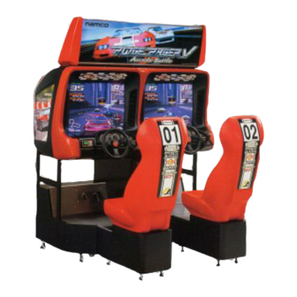
1. SPECIFICATIONS POWER SUPPLY:- 230v /350watts AC AMBIENT OPERATING +5°C to +25°C TEMPERATURE MONITOR:- Hantarex 28” Polo-Medium Planar (Type 02193240) COIN ACCEPTOR:- Mars CashFlow - 4 Channel Dispense DIMENSIONS:- Assembled 1600(w) x 1630(w) x 1990(h) Monitor Cabinet 1600(w) x 870(d) x 1590(h) Seat Assembly 452(w) 820(d) x 1220(h) -
Page 29: How To Play
2. HOW TO PLAY This is a multi-play car racing game, which can be played by one or two people. The player(s) compete against computer cars. [Game Overview] • The object of the game is to complete a specified number of laps in the given time period. -
Page 30: Major Components
3. MAJOR COMPONENTS Fluorescent lamp Header Assy Game PCB Assy Mains-In and ON / OFF switch Game PCB Assy Monitor Control panel Assy Control panel Assy Steering Assy Brake pedal Assy Accelerator pedal Assy Seat Assy Coin Assy Seat Assy Page 30... -
Page 31: Moving The Machine
4. MOVING THE MACHINE This machine is fitted with castors to make it easier to move. Take care when moving the machine on an inclined surface. The overall height of this machine is 1990mm. Take care of any overhead obstructions. (e.g. Light Fittings, Electric Cables etc.) When moving the game , ensure that the game is dis-assembled into 4 parts: Monitor Cabinet, Header Assembly and Seat Assemblies. - Page 32 This machine is designed for INDOOR USE ONLY. Do not install in the following places. Outdoors Direct Sunlight, places with excessive humidity or dust, places where there is water leakage, near air-conditioning or heating equipment, places with excessive heat or cold temperature. Places where it would be in the way of emergency exits or fire extinguishing equipment.
- Page 33 CETTE MACHINE EST DESTINEE UNIQUEMENT A UN USAGE INTERIEUR NE PAS INSTALLER LA MACHINE DANS LES ENDROITS SUIVANTS A l’extérieur. Directement exposée au soleil, aux endroits excessivement humides ou poussiéreux, aux endroits où il y a des risques de fuite d’eau, près de ventilateurs ou source de chaleur, aux endroits très chauds ou froids.
- Page 34 ESTA MAQUINA FOI CONCEBIDA PARA UTILIZAÇÃO EM ESPACOS INTERIORES APENAS NÃO INSTALAR A MAQUINAS NOS SEGUINTES LOCAIS:- Exteriores. `Luz solar directa, locais com humidade excessiva ou pó, locais aonde existam fugas de água perto de ar condicionados ou equipamentos calorificos e locais com temperaturas excessivamente quentes ou frias.
-
Page 35: Fitting The Header Assembly
5-2 Fitting the Header Assembly The Header Assembly has a forward centre of gravity, so it is important that at least two people are used to fit or remove the Header Assembly. The fitting position of the Header Assembly is very high, and it is important that a means of reaching the height safely , without stretching, is available (e.g. - Page 36 Fit the 3off pozi head screw, with flat and spring washer, (M6x16) to retain the Header Assembly in position. Pozi head screw (with flat/spring washers) (M6 x 16) Header Assy Page 36...
-
Page 37: Fitting The Seat Assemblies
5-3 Fitting the Seat Assemblies Remove 10off security screw (M5x16) and remove both floor plates. Place the Seat Assemblies up to the Monitor Cabinet and set the adjustable feet so that the seat base is level with the main cabinet. Connect the connectors. -
Page 38: Adjusting The Level Adjusters
5-4 Adjusting the Level Adjusters When the assembled game is in its final position, lower the twelve (12) level adjusters,(4off Monitor Assy and 4off each Seat Assy), with a spanner so that the machine is level and all castors are raised from the floor by approx. -
Page 39: Fitting The Game Pcb Security Cards
5-6 Fitting the Game PCB Security Cards • The Security Cards are designed for this Game only. Do not use them with other models. Do not insert any other Security Cards. These may result in malfunctions. • Always turn OFF the power before inserting the Security cards. •... -
Page 40: Fitting The Cd Rom
5-7 Fitting the CD Rom • The supplied CD-ROMs are designed for this game only. Do not use them with othergames. Do not insert any other CD-ROMs. These may result in malfunction. • Always install one CD-ROM to each Game PCB Assy. •... -
Page 41: Adjustments
6. ADJUSTMENTS Adjustment or maintenance on this machine should be carried out by qualified personnel only. Einstellungen und Wartung des Gerätes dürfen nur von dafür qualifiziertem Fachpersonal vorgenommen werden. Justeringer eller vedligehold af denne maskine bør kun udføres af kvalificeret personale. Los ajustes y el mantenimiento de esta máquina deben ser realizados sólo por personal cualificado. -
Page 42: Adjustment Switches
6-2 Adjustment Switches The Adjustment switches are located inside the coin door. Service Switch. Press this switch to obtain game credits without incrementing the play meter. Test Switch Slide the test switch ON to enter test mode. Test mode allows testing and the changing of game settings. (Refer to section 6-3 "Test Mode"... -
Page 43: Test Mode
6-3 Test Mode Open the coin door and slide the test switch “ON”. The “Menu Screen” will be displayed on the monitor. Select the test required by using the select up/down switch. The colour of the selected test will change. Activate the test by pressing the Enter switch. -
Page 44: Coin Options
6-3-1 Coin Options Select “COIN OPTIONS” on the menu screen to set the game cost and related settings. The following screen is displayed. Use the Select Up/Down switch choose the required item then press the Enter button. Use the Select Up/Down switch to change the setting. Press the Enter button to return to option select mode. -
Page 45: Game Options
6-3-2 Game Options Select “GAME OPTIONS” on the menu screen to set the game variables, the following screen is displayed. Use the Select Up/Down switch to choose the required item then press the Enter button. Use the Select Up/Down switch to change the setting. Press the Enter button to return to option select mode. - Page 46 s t i a l i , ) t z i l ) f ( z i l z i l z i l z i l c i f y t l t i t ) i ( n i l ) j ( y l l c i f...
-
Page 47: I/O Test
6-3-3 I/O Test Select “I/O TEST” on the menu screen to test the switches and lamps. The following screen is displayed. Use the Select Up/Down switch to choose the required item then press the Enter button to enter the test. Select “EXIT”... -
Page 48: I/O Pcb Test
DIP SW 1234 [ON : RED] LINK LINK AS 1 (LEFT) I / O PCB CHECK namco ltd: FCA-1: ver 1.00: EXP Multipurpose + Rotary Encoder I/O PCB CONNECT OK NAMCO LTD. EXIT SELECT SW : CHOOSE ENTER SW : ENTER... -
Page 49: Switch Test
6-3-3-3 Switch Test Select “Switch Test” on the I/O menu screen to test the switches. The following screen is displayed. The display shows the current state of the switches. Press the Up Select switch and the Enter switch together to EXIT and return to the I/O menu screen I / O TEST DIP SW... -
Page 50: Lamp Test
6-3-3-4 Lamp Test Select ‘LAMP TEST’ from the I/O Test Screen. The following screen is displayed:- I / O TEST DIP SW 1234 [ON : RED] LINK LINK AS 1 (LEFT) LAMP TEST VIEW CHANGE EXIT SELECT SW : CHOOSE ENTER SW : ENTER (a) The View Change lamp will turn On or OFF each time the Enter switch is pressed, and the display will change from OFF to ON. -
Page 51: Monitor Test
6-3-4 Monitor Test Select “MONITOR TEST” on the menu screen to test and adjust the Monitor. The following screen is displayed. Use the Select Up/Down switch to choose the required item then press the Enter button. To return to the Monitor Test Menu from a test pattern press the Enter button. -
Page 52: Sound Test
6-3-5 Sound Test Select “SOUND TEST” on the menu screen to test the audio and adjust the volume settings. The following screen is displayed. Use the Select Up/Down switch to choose the required item then press the Enter button. Use the Up/Down switch to change the setting. Press the Enter button to return to item select mode Select “EXIT”... -
Page 53: Cd Test
6-3-6 CD Test Select “CD TEST” on the menu screen to test the CD Read-In. The following screen is displayed. Use the Select Up/Down switch to choose the required item then press the Enter button to enter the test. Select “EXIT” and press the Enter button to return to the menu screen. CD TEST TYPE INITIALIZE... -
Page 54: Ads Data
6-3-7 ADS Data By selecting ADS Data from the menu screen, all of the bookkeeping details can be read and/or reset. 6-3-8 Others Select “OTHERS” on the menu screen. The following screen is displayed. Use the Select Up/Down switch choose the required item then press the Enter button. -
Page 55: Initialization
7. INITIALIZATION Adjustments when Replacing Parts The following operation must always be performed after replacing the Game PCB, Rom, or Control Potentiometers. The game will not operate correctly if these adjustments are not made. Slide the TEST switch ON while pressing the SERVICE switch . The following screen is displayed. -
Page 56: Maintenance
8. MAINTENANCE Adjustment or maintenance on this machine should be carried out by qualified personnel only. Ensure that the POWER to the machine is turned OFF before commencing any maintenance work. (Trouble shooting, service or repairs etc.) Einstellungen und Wartung des Gerätes dürfen nur von dafür qualifiziertem Fachpersonal vorgenommen werden. - Page 57 Aanpassingen of onderhoud aan deze machine dient alleen uitgevoerd te worden door bekwaam personeel. Zorg ervoor dat de machine UITgeschakeld is voordat er enig onderhoudswerk wordt verricht (troubleshooting, reparaties etc.) Afinações ou manutenção nesta maquina, deverão ser efectuadas sómente por pessoal qualificado. Certifique-se que a maquina se encontra desligada sempre que iniciar qualquer tipo de trabalho de manutenção.
-
Page 58: Error Messages
8-1 Error Messages The machine automatically executes a self-test when the power is turned ON. If the machine is normal, the startup screen appears on the monitor. If there is something wrong, the machine beeps or displays an error message on the monitor, and stops operation. -
Page 59: Replacing The Cd Rom Drive
8-2 Replacing the CD Rom Drive Ensure that the Power to the game is turned OFF before starting work. Remove the Monitor Cabinet Lower Rear Door. Remove the CD Rom and place the CD Rom in a safe place. (see 5-7 page 40) Disconnect the 7 connectors (shaded) as shown below. - Page 60 Disconnect the three connectors as shown shaded in the figure below. Remove 1off pozi head screw (M4x10), with flat and spring washer, and remove the CD Drive in the direction of the arrow, as shown below, taking care not to bend the hook on the rear of the Drive. CD-ROM drive Connectors Hook...
-
Page 61: Replacing The Steering Pcb And/Or Fuse
8-3 Replacing the Steering PCB and/or Fuse Remove 8off button head screws (M5x12) and remove the Monitor Cabinet Rear Cover. Replace the fuse or: Disconnect the six connectors shown shaded in the diagram below. Loosen 2off pozi head screws (M6), lift the PCB Base to disengage it from the screws and remove the PCB with the PCB Base. -
Page 62: Repacing The Amplifier Pcb
8-4 Repacing the Amplifier PCB Remove the floor plates. (see 5-3 page 37) Disconnect the connectors shown shaded in the diagram below. To remove the Amplifier PCB from the locking supports, squeeze the tabs of the support together and gently lift the PCB upwards. Repeat for each support. -
Page 63: Replacing The Fluorescent Lamp Or Starter
8-5 Replacing the Fluorescent Lamp or Starter. Remove 3off button head screws (M5x12) and remove the top retaining bracket. Remove the Header Acrylic. Button head screw (M5 x 12) Top Retaining Bracket Header Acrylic Replace the Fluorescent tube or starter. Starter Fluorescent lamp Reassemble in reverse order. -
Page 64: Replacing The Gear Shift Assy
8-6 Replacing the Gear Shift Assy Remove 4off security screws (M6x16). Lift the Gear Shift Assembly only sufficient to disconnect the connector. Security screw (M6 x 16) Gear Shift Assy Connector Remove the Gear Shift Assy. Reassemble in reverse order. Page 64... -
Page 65: Replacing The Gear Shift Microswitch
8-6-1 Replacing the Gear Shift Microswitch remove the Gear Shift Assy. (see 8-6 page 64) Disconnect the Fast-On connectors. Remove 2off pozi head screws and remove the Microswitch. Pozi head screw (M3x16) Microswitch Reassemble in reverse order. Page 65... -
Page 66: Removing The Play Panel Assy
8-7 Removing the Play Panel Assy Remove the Gear Shifter Assy. Remove 6off security screw (M5x20) and lift the Play Panel only sufficient to access the connector. Security screw (M5 x 20) Control panel Assy Security screw (M5 x 20) Disconnect the connector and lift the Play Panel Assy away. -
Page 67: Replacing The View Change Switch
8-8 Replacing the View Change/Credit Available Switches Remove the Play Panel Assy. (see 8-7 page 66) Remove the switch/lamp assembly by pulling it out from the switch body. Replace the switch or lamp. View change switch Control panel Assy View change switch Yellow White White/Black... -
Page 68: Replacing The Steeering Assembly
8-9 Replacing the Steeering Assembly Remove the Play Panel Assy. (see 8-7 page 66) Disconnect the Steering Motor and Steering Potentiometer connectors. Remove 4off hex head screws (M8x25) and remove the Steering assembly. Hex head screw (M8x25) Hex head screw (M8x25) Reassemble in reverse order Page 68... -
Page 69: Replacing The Steering Potentiometer
8-10 Replacing the Steering Potentiometer Remove the steering assembly. (see 8-9 page 68) Remove 2off hex socket head screws (M4x10) holding the potentiometer mounting bracket to the front plate. Slacken the grub screw (M4x10) and remove the potentiometer complete with the mounting bracket. Hex socket head screw (M4x10) Grub screw (M4x10) Mounting bracket... -
Page 70: Replacing The Drive Belt
8-11 Replacing the Drive Belt Remove the steering assembly. (see 8-9 page 68) Slacken the adjustment screw (hex head M6x60). Slacken the 4off hex nuts to remove the tension from the belt. Belt Hex head screw (Mx60) Hex nut (M5) Replace the drive belt. -
Page 71: Removing The Steering Wheel
8-12 Removing the Steering Wheel Remove 3off countersunk socket head screws and remove the centre cap. Remove 3off countersunk socket head screws and remove the steering wheel. Steering wheel Centre cap Countersunk socket head screw (M3x16) Countersunk socket head screw (M6x26) Note: When replacing the steering wheel ensure that the steering wheel... -
Page 72: Removing The Pedal Assy
8-13 Removing the Pedal Assy Remove 4off button head screws (M5x20). Accelerator pedal assy Brake pedal Assy Connectors Pedal plate Button head screw (M5 x 12) Withdraw the pedal assembly only sufficiently to disconnect the connectors. Remove the pedal assembly. Reassemble in reverse order Page 72... -
Page 73: Replacing The Pedal Potentiometer
8-14 Replacing the Pedal Potentiometer Remove the pedal asembly. (see 8-13 page 72) Slacken the hex socket screw (M4x8) and remove the potentiometer complete with potentiometer bracket. Accelerator pedal Assy Hexagonal wrench Hex socket screw (M4 x 8) Ground lead Brake pedal Assy Whizztite Nut Connector... -
Page 74: Replacing The Brake Damper
8-15 Replacing the Brake Damper Remove the pedal assemble. (see 8-13 page 72) Remove 4off flange socket head screws (M6x8) and remove the brake damper assy. Flange socket (M6 x 8) Flange socket (M6 x 8) Brake damper Replace the damper assy and reassemble in reverse order. Note: After replacing the damper ensure that the game is re-initialized. -
Page 75: Replacing The Pedal Stop Rubber
8-16 Replacing the Pedal Stop Rubber Remove the pedal assembly. (see 8-13 page72) Hexagonal bolt (M6 x 60) Countersunk washer nut Cushion and spacer Cross section Spacer Cushion Remove the countersunk washer nut and hex head screw (M6x60). Replace the stop rubber. Reassemble in reverse order. -
Page 76: Replacing The Monitor
8-17 Replacing the Monitor THE POWER TO THE GAME MUST BE SWITCHED OFF BEFORE REMOVING THE MONITOR. The monitor is heavy. Ensure that at least two people are available to remove the monitor, and ensure that there is sufficient space to work safely. - Page 77 Remove 6off security screw (M5x20) and remove the Monitor Face CTR. Security screw (M5 x 20) Monitor face CTR Security screw (M5 x 20) Remove 5off security screw (M5x20) and remove the Monitor Face UPR, Monitor Face and Monitor Mask as one assembly. Monitor face UPR Security screw (M5 x 20) Monitor mask...
- Page 78 Remove 4offpozi head screws (M5x12) and remove the top bracket. Top bracket Pozi head screw (M5 x 12) Remove 2off pozi head screw(M5x12) and remove the Mask Bracket. Pozi head screw (M5 x 12) Mask bracket Page 78...
- Page 79 Remove 4off Pozi head screws (M8x20), with flat and spring washers, holding the Monitor in place. Monitor Washer (M8) Washer (M8) Pozi head screw (M8x20) (with flat/spring washer) 10. Slowly tilt the monitor forward and then lift the monitor out from the front. Monitor 11.
-
Page 80: Parts
9. PARTS 9-1 Monitor Cabinet Opposite side Opposite side Opposite side Cross section B-B Cross section C-C Page 80... - Page 81 " 8 a l l a l l e l l ½ " Page 81...
-
Page 82: Header Assy
9-2 Header Assy Opposite side c i l c i l t t i Page 82... -
Page 83: Mains-In Assy And Service Bracket
9-3 Mains-In Assy and Service Bracket d i l c t i c t i c t i t l i Page 83... -
Page 84: Play Panel Assy
9-4 Play Panel Assy a l i a l i Page 84... -
Page 85: Steering Assy
9-5 Steering Assy Page 85... -
Page 86: Shifter Assy
9-6 Shifter Assy t f i Page 86... -
Page 87: Accelerator Pedal Assy
9-7 Accelerator Pedal Assy Cross section A-A Page 87... -
Page 88: Brake Pedal Assy
9-8 Brake Pedal Assy Cross section A-A Page 88... -
Page 89: Game Pcb Assy
9-9 Game PCB Assy ½ " Page 89... -
Page 90: Seat Assy
9-10 Seat Assy d i l ½ " Page 90... -
Page 91: Schematic
HEADER Assy AMP UNIV 3w AMP UNIV 3w AMP EI 3w AMP EI 3w White / Blue White / Blue BROWN FLUORESCENT Assy STEERING White / Red White / Red STEERING GRN/YEL STEERING STEERING BLUE V257 STR PCB V257 Ass (L) STR PCB White / Black White / Black... - Page 92 Copies of Namco Game Manuals can be downloaded from our website: www.namco.co.uk/html/spares/index.htm For all Parts or Technical Support contact: Brent Spares, Namco House, Units 5-8, Acton Park Estate, The Vale, London. W3 7QE www.namco.co.uk For Technical Support, Warranty and Advance Replacement Parts:-...