Table of Contents
Advertisement
Quick Links
Download this manual
See also:
User Manual
Car Audio
TA B L E OF CO NT E NT S
Location of PCBS........................... ...1-1
Specifications................................. ...1-2
Measurement setup..................... ......1-3
Service aids................................. ...1-4
Instructions on cd playability............1-5/6
Disassembly diagram...... ..................2
Malfunction check chart..................... ...3-2
Wiring diagram........................... ...... ...4-1
Main board-circuit diagram-1...............5-1
Main board-circuit diagram-2...............5-2
Pcb layout top/bottom view..................5-3
Servo board-circuit diagram-1............ ...6-1
1228 BG LE
WW
Ve rs ion 1 .1
Servo board-circuit diagram-2...............6-2
Layout diagram top/bottom view... ... ... ...6-3
SB+CB board-circuit diagram...............7-1
SB+CB board-layout top/bottom view......7-2
LB+SD+CB board-circuit diagram...............8-1
-1 2
/
KEY board-circuit diagram..................9-1
KEY-
layout diagram top/ bottom view
Exploded view-main unit.....................10-1
CED230
.........9-2
314178537781
Advertisement
Table of Contents

Summary of Contents for Philips CED230
-
Page 1: Table Of Contents
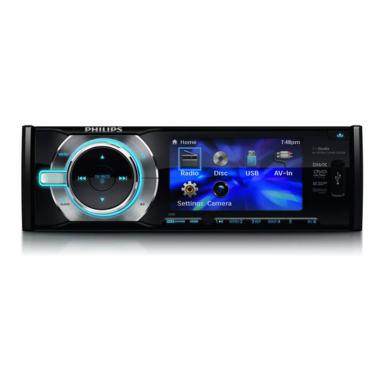
Car Audio CED230 TA B L E OF CO NT E NT S Location of PCBS……………………… …1-1 Servo board-circuit diagram-2……………6-2 Layout diagram top/bottom view… … … …6-3 Specifications…………………………… …1-2 Measurement setup………………… ……1-3 SB+CB board-circuit diagram……………7-1 Service aids…………………………… …1-4 SB+CB board-layout top/bottom view……7-2 Instructions on cd playability…………1-5/6... -
Page 2: Location Of Pcbs
1- 1 L oc ation of P C B s MAIN BOARD KEY BOARD SERVO BOARD SD BOARD LONG BOARD CONNECT BOARD VERSION VARIATIONS: CED230(X) Type/Versions Service policy Board inused: MAIN BOARD SERVO BOARD KEY BOARD CONNECT BOARD SD BOARD... -
Page 3: Specifications
SPECIFICATIONS General Tuner Power supply: 12V DC(11V -16V Frequency range 87. 5-108.0MHz(Eur) negative ground 65. 0-74.0MHz(OIRT) Fuse: 87. 5-107.9MHz(Ame) Suitable speaker impedance: 4-8Ω Frequency range 522-1620KHz(Eur) Maximum power output: 45Wx4channels -AM(MW) 530-1710MHz(Ame) Continuous power output: 18Wx4channels(4Ω 10% T.H.D.) Usable sensitivity Pre-Amp output voltage: 2.0V(CD play mode;... -
Page 4: Measurement Setup
MEASUREMENT SETUP Tuner FM Bandpass LF Voltmeter 250Hz-15kHz e.g. PM2534 e.g. 7122 707 48001 RF Generator e.g. PM5326 S/N and distortion meter e.g. Sound Technology ST1700B Use a bandpass filter to eliminate hum(50Hz,100Hz) and disturbance from the pilottone(19kHz,38kHz). Tuner AM (MW,LW) Bandpass LF Voltmeter 250Hz-15kHz... -
Page 5: Service Aids
SERVICE AIDS WARNING All ICs and many other semi-conductors are susceptible to electrostatic discharges (ESD). Careless handling during repair can reduce life drastically. When repairing, make sure that you are connected with the same potential as the mass of the set via a wrist wrap with resistance. Keep components and tools also at this potential. -
Page 6: Instructions On Cd Playability
INSTRUCTIONS ON CD PLAYABILITY Customer complaint " CD related problem" Set remains closed! ① Check playability playability For flap loaders(=access to CD drive possible) ③ clesning method④is recommended "fast" lens cleaning check playability playability Play a CD for at least 10 minutes check playability playability ann lnfo for customer... -
Page 8: Disassembly Diagram
Disassembly Diagram 1、P ull out the mounting collar from the 2、Press the release key first, 3、loosen and take out the two bolts 4、Take out the top cover with a forceps. main set with two L-keys. then take out the panel. with a screw-driver. - Page 9 Disassembly Diagram 、 、 、 11 loosen and take out the bolt 12 loosen and take out the bolt 13 loosen and take out the bolt with a screw-driver, with a screw-driver, with a screw-driver, 14、P ull out the two pieces of connection-pegs 15、Loosen and take out the six bolts carefully with a screwdriver.
-
Page 10: Software Version Check&Upgrade
Software version check & upgrade Upgrade software Check MCU software version When the device is power on at the first time, in USB/SD/Disc mode, press the key in turn: 1. Copy the file "MCU.BIN" into USB stick stop down left right 2. -
Page 11: Malfunction Check Chart
Malfunction check chart TDA7388 of main Change main Main board which in Main board Check tuner circuit and its conjoint part is good or bad SD no read USB no read Whether connect to SD Whether connect to USB Check the socket of SD Check the socket of USB Change servo Change servo... -
Page 12: Wiring Diagram
WIRING DIAGRAM... -
Page 13: Main Board-Circuit Diagram-1
MAIN BOARD-CIRCUIT DIAGRAM-1... -
Page 14: Main Board-Circuit Diagram-2
MAIN BOARD-CIRCUIT DIAGRAM-2... -
Page 15: Pcb Layout Top/Bottom View
MAIN BOARD-PCB LAYOUT TOP/BOTTOM VIEW... -
Page 16: Servo Board-Circuit Diagram-1
SERVO BOARD-CIRCUIT DIAGRAM-1... -
Page 17: Servo Board-Circuit Diagram-2
SERVO BOARD-CIRCUIT DIAGRAM-2... -
Page 18: Layout Diagram Top/Bottom View
SERVO BOARD-LAYOUT DIAGRAM TOP/BOTTOM VIEW... -
Page 19: Sb+Cb Board-Circuit Diagram
SB+CB BOARD-CIRCUIT DIAGRAM... -
Page 20: Sb+Cb Board-Layout Top/Bottom View
SB+CB BOARD-PCB LAYOUT TOP/BOTTOM VIEW... -
Page 21: Lb+Sd+Cb Board-Circuit Diagram
LB+SD+CB BOARD-CIRCUIT DIAGRAM... -
Page 22: Lb+Sd+Cb Board-Layout Top/Bottom View
LB+SD +CB BOARD- LAYOUT TOP/BOTTOM VIEW... -
Page 23: Key Board-Circuit Diagram
KEY BOARD-CIRCUIT DIAGRAM... - Page 24 KEY BOARD-LAYOUT DIAGRAM TOP/ BOTTOM VIEW...
-
Page 25: Exploded View-Main Unit
10-1 10-1 EXPLODED VIEW-MAIN UNIT...


