Table of Contents
Advertisement
TABLE OF CONTENTS
1 Safety Precautions----------------------------------------------- 2
1.1. Information for Your Safety------------------------------ 2
1.2. Cautions for use ------------------------------------------- 3
2 Service Navigation ----------------------------------------------- 4
2.1. Introduction-------------------------------------------------- 4
2.2. Important Notice ------------------------------------------- 4
3 Specifications ----------------------------------------------------- 5
3.1. Specifications (Rated) ------------------------------------ 5
3.2. Accessories ------------------------------------------------- 5
4 Location of Controls and Components ------------------- 6
5 Service Fixture & Tools----------------------------------------- 7
5.1. Service Fixture and Tools-------------------------------- 7
5.2. Clean Box --------------------------------------------------- 7
6 Disassembly and Assembly Instructions ---------------- 8
6.1. Outline-------------------------------------------------------- 8
6.2. Disassembly Flow Chart --------------------------------- 8
6.3. Disassembly procedure ---------------------------------- 9
6.4. Assembly Flow Chart ------------------------------------ 11
6.5. Assembly procedure -------------------------------------12
7 Maintenance-------------------------------------------------------15
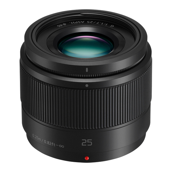
Interchangeable Lens for Digital Camera
Model No.
Coulor
(K)..........Black Type
(S)..........Silver Type
PAGE
7.1. ABOUT THE LENS -------------------------------------- 15
8 Exploded View and Replacement Parts List ----------- 16
ORDER NO. DSC1510023CE
H-H025PP
H-H025E
H-H025GK
© Panasonic Corporation 2015 Unauthorized copy-
ing and distribution is a violation of law.
B26
PAGE
Advertisement
Table of Contents

Related Manuals for Panasonic H-H025PP


Summary of Contents for Panasonic H-H025PP
-
Page 1: Table Of Contents
6.1. Outline-------------------------------------------------------- 8 6.2. Disassembly Flow Chart --------------------------------- 8 6.3. Disassembly procedure ---------------------------------- 9 6.4. Assembly Flow Chart ------------------------------------ 11 6.5. Assembly procedure -------------------------------------12 7 Maintenance-------------------------------------------------------15 © Panasonic Corporation 2015 Unauthorized copy- ing and distribution is a violation of law. -
Page 2: Safety Precautions
1 Safety Precautions 1.1. Information for Your Safety... -
Page 3: Cautions For Use
1.2. Cautions for use... -
Page 4: Service Navigation
2 Service Navigation 2.1. Introduction This service manual contains technical information, which allow service personnel’s to understand and service this model Please place orders using the parts list and not the drawing reference numbers. If the circuit is changed or modified, the information will be followed by supplement service manual. 2.2. -
Page 5: Specifications
3 Specifications 3.1. Specifications (Rated) 3.2. Accessories... -
Page 6: Location Of Controls And Components
4 Location of Controls and Components... -
Page 7: Service Fixture & Tools
5 Service Fixture & Tools 5.1. Service Fixture and Tools The following Service Fixture and Tools are used for Checking & Servicing for this unit. 5.2. Clean Box • The repair quality is considered, and it is recommended working in the environment of satisfied clean level less than class 10,000 (Federal Standard 209D). -
Page 8: Disassembly And Assembly Instructions
6 Disassembly and Assembly Instructions 6.1. Outline Please be disassembly and assembly with reference to the flow chart and illustrations drawings. Important: 1. It is recommended dealing with Clean Box, to keep maintaining the dustproof environment. (Refef to " 5.2. Clean Box " section of this Service Manual for details.) 2. -
Page 9: Disassembly Procedure
6.3. Disassembly procedure 6.3.3. Removal of the Shading Frame 1. Remove 2 screws (B) and the Shading Frame. 6.3.1. Removal of the Deco. Ring Unit 1. Deco. Ring Unit is sticked on the Filter Ring. 2. Put the sheet so that the lens glass is fullty covered. 3. - Page 10 6.3.5. Removal of the Lens P.C.B. Unit 6.3.6. Removal of the Rear Frame Unit and the Lens Mount Contact Unit 1. Remove 3 screws (F) and the Rear Frame Unit. 1. Remove 2 screws (E) and disconnect 5 connectors. 2. Remove the Lens P.C.B. Unit and the Lens Mount Con- nect Unit.
-
Page 11: Assembly Flow Chart
6.4. Assembly Flow Chart... -
Page 12: Assembly Procedure
6.5. Assembly procedure 6.5.2. Installation of the Deco. Ring Unit 1. Please insert the 3 protrusions of the Deco. Ring Unit Important: back to 3 holes of the Filter Ring. 1. When tightening the screw, use a torque driver (Caution) (RFKZ0456) by ordering the screwing order with specified •... - Page 13 6.5.3. Installation of the Rear Frame Unit 6.5.4. Installation of the Lens P.C.B. Unit and the Lens Mount Contact Unit 1. Install the Rear Frame Unit. 2. Tighten 3 screws (F) by using the torque driver with spec- 1. Connect FPC of the Lens Mount Connect Unit to connec- ified torque.
- Page 14 6.5.5. Installation of the L Mount Unit 6.5.6. Installation of the Shading Frame 1. Install the L Mount Unit. 1. Install the Shading Frame. 2. Tighten 1 screw (C) and 3 screws (D) in numerical order 2. Tighten 2 screws (B) in numerical order by using the by using the torque driver with specified torque.
-
Page 15: Maintenance
7 Maintenance 7.1. ABOUT THE LENS 7.1.1. DUST/DIRT ON THE OUTER CASING PART(S) 1. Blow off the dust first, then sweep out the dust from narrower spaces with soft cleaning brush. 2. Wipe up the Outer casing part with the dry fuzz-free cloth. 7.1.2. -
Page 16: Exploded View And Replacement Parts List
8 Exploded View and Replacement Parts List Please click the radio button for "Diagrams II / Parts List" on the menu bar in XML Service Manual. If you want to print, please click the icon button for "Print" on the icon bar and select the item.