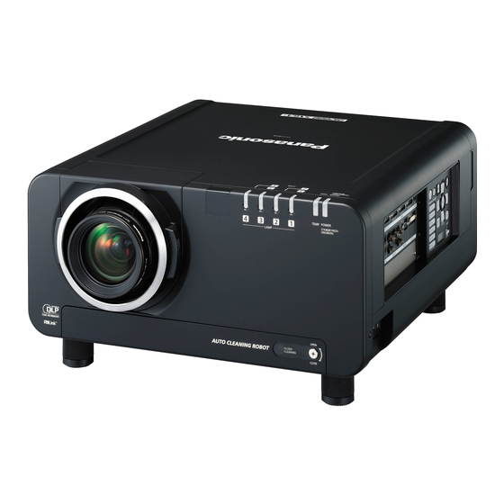
Panasonic PT-DZ12000U Service Manual
Dlp based projector
Hide thumbs
Also See for PT-DZ12000U:
- Operating instructions manual (200 pages) ,
- Brochure & specs (6 pages) ,
- Setup and operation manual (37 pages)
Table of Contents

Related Manuals for Panasonic PT-DZ12000U


Summary of Contents for Panasonic PT-DZ12000U
- Page 1 ORDER NO. VED0809388C0 DLP Based Projector PT-DZ12000U PT-DZ12000E PT-D12000U PT-D12000E PT-DW100U PT-DW100E © 2008 Matsushita Electric Industrial Co., Ltd. All rights reserved. Unauthorized copying distribution is a violation of law.
- Page 2 PT-DZ12000U / PT-DZ12000E / PT-D12000U / PT-D12000E / PT-DW100U / PT-DW100E...
-
Page 3: Table Of Contents
PT-DZ12000U / PT-DZ12000E / PT-D12000U / PT-D12000E / PT-DW100U / PT-DW100E CONTENTS Page Page 1 Safety Precautions 12.13. Removal of R3-P.C.Board 1.1. General Guidelines 12.14. Removal of S-P.C.Board 1.2. Leakage Current Check 12.15. Removal of SL-P.C.Board 1.3. UV Precaution and UHM Lamp Precautions 12.16. - Page 4 PT-DZ12000U / PT-DZ12000E / PT-D12000U / PT-D12000E / PT-DW100U / PT-DW100E 16.18. J2/J3/L1/L2/L3/L4-P.C.Board 17.2. A-P.C.Board (Component Side) 16.19. R/R2/R3/SL/CL-P.C.Board 17.3. G-P.C.Board (Foil Side) 16.20. S-P.C.Board 17.4. G-P.C.Board (Component Side) 16.21. B-Module (1/2) 17.5. S-P.C.Board 16.22. B-Module (2/2) 18 Terminal guide of ICs and transistors...
-
Page 5: Safety Precautions
PT-DZ12000U / PT-DZ12000E / PT-D12000U / PT-D12000E / PT-DW100U / PT-DW100E 1 Safety Precautions 1.1. General Guidelines · For continued safety, no modification of any circuit must be attempted. · Unplug the power cord from the power outlet before disassembling this projector. -
Page 6: Specifications
PT-DZ12000U / PT-DZ12000E / PT-D12000U / PT-D12000E / PT-DW100U / PT-DW100E 2 Specifications... - Page 7 PT-DZ12000U / PT-DZ12000E / PT-D12000U / PT-D12000E / PT-DW100U / PT-DW100E...
-
Page 8: Function For Safety
PT-DZ12000U / PT-DZ12000E / PT-D12000U / PT-D12000E / PT-DW100U / PT-DW100E 3 Function for Safety 3.1. Temperature Detection inside the Lamp Unit This projector has 2 bimetals contacting the lamp units to protect the lamps. If the temperature of one of the lamp units exceeds 150°C, the bimetals will operate to turn off the power. -
Page 9: Setting To Serviceman Mode
PT-DZ12000U / PT-DZ12000E / PT-D12000U / PT-D12000E / PT-DW100U / PT-DW100E 4.1. Setting to Serviceman Mode Press the MENU button. The MAIN MENU screen will be displayed. Select “PROJECTOR SETUP” using the buttons and press the ENTER button. The PROJECTOR SETUP screen will be displayed. -
Page 10: Functions In Serviceman Mode
PT-DZ12000U / PT-DZ12000E / PT-D12000U / PT-D12000E / PT-DW100U / PT-DW100E Select SERVICE PASSWORD using the buttons and press the ENTER button. The SERVICE PASSWORD screen will be displayed. Input the password "0000" with the numeric buttons (0 to 9) of the remote control unit and press the ENTER button. - Page 11 PT-DZ12000U / PT-DZ12000E / PT-D12000U / PT-D12000E / PT-DW100U / PT-DW100E − − − − WHITE: 10% - 100% − − − − DARK GRAY: 1 - 10 − − − − COLOR: 1 - 2 of Red, Green, Blue, Cyan, Magenta and Yellow 4.3.6.
- Page 12 PT-DZ12000U / PT-DZ12000E / PT-D12000U / PT-D12000E / PT-DW100U / PT-DW100E...
- Page 13 PT-DZ12000U / PT-DZ12000E / PT-D12000U / PT-D12000E / PT-DW100U / PT-DW100E 4.3.7. Additional Function for RS-232C in PROJECTOR SETUP menu · SIGNAL SELECTOR ON: Sets it when an optional signal selector is connected. OFF: Default setting 4.3.8. Additional Function for AIR FILTER CLEANING in PROJECTOR SETUP menu ·...
-
Page 14: Self-Diagnosis Display
PT-DZ12000U / PT-DZ12000E / PT-D12000U / PT-D12000E / PT-DW100U / PT-DW100E IGNORE: Does not control the shutter when power OFF. · CINEMA FILTER NONE: Default setting INSTALLED: When installing the color filter that expands the color region · AIR FILTER NORMAL: Default setting SPECIAL: Sets it when the smoke cut filter is installed. - Page 15 PT-DZ12000U / PT-DZ12000E / PT-D12000U / PT-D12000E / PT-DW100U / PT-DW100E Self- Contents Shutdown Display condition Remarks diagnosis display Optical output restriction for the 40 °C (35 °C when ALTITUDE MODE is ON) or projector protection higher in ambient temperature at QUAD mode...
-
Page 16: Comparison Table Of Self-Diagnosis Display And Code
PT-DZ12000U / PT-DZ12000E / PT-D12000U / PT-D12000E / PT-DW100U / PT-DW100E Self- Contents Shutdown Display condition Remarks diagnosis display Fan error 1: P-UNIT FAN Power unit fan Fan error 2: LAMP FAN 1 Lamp fan 1 Fan error 3: LAMP FAN 2... - Page 17 PT-DZ12000U / PT-DZ12000E / PT-D12000U / PT-D12000E / PT-DW100U / PT-DW100E Self-diagnosis Code Self-diagnosis Code display display 00000000 00000000 00000000 00000002 00000000 00000000 00100000 00000000 00000000 00000000 00000000 00000004 00000000 00000000 00200000 00000000 00000000 00000000 00000000 00000008 00000000 00000000 00400000 00000000...
-
Page 18: Using The Serial Terminals
PT-DZ12000U / PT-DZ12000E / PT-D12000U / PT-D12000E / PT-DW100U / PT-DW100E 6 Using the Serial Terminals THe main unit is equipped with SERIAL terminals located in its terminal section on the side, and this terminal is compliant with RS- 232C/RS-422. Also a serial output terminal is provided to enable plural projector control. -
Page 19: Pin Assignments And Signal Names
PT-DZ12000U / PT-DZ12000E / PT-D12000U / PT-D12000E / PT-DW100U / PT-DW100E 6.2. Pin Assignments and Signal Names RS-232C RS-422 6.3. Communication Conditions (Factory Setting) 6.4. Procedure of Communication Condition Settings Press the MENU button. The MAIN MENU screen will be displayed. -
Page 20: Control Commands
PT-DZ12000U / PT-DZ12000E / PT-D12000U / PT-D12000E / PT-DW100U / PT-DW100E Press the ENTER button. The PROJECTOR SETUP screen will be displayed. Select RS-232C using the buttons. Press the ENTER button. The RS-232C screen will be displayed. Select SERIAL IN using the buttons. - Page 21 PT-DZ12000U / PT-DZ12000E / PT-D12000U / PT-D12000E / PT-DW100U / PT-DW100E Note To connect the computer to the SERIAL terminal, prepare an adequate communication cable that fits to your personal computer.
-
Page 22: Using A Wired Remote Control
PT-DZ12000U / PT-DZ12000E / PT-D12000U / PT-D12000E / PT-DW100U / PT-DW100E 7 Using a Wired Remote Control 7.1. Connection Example When multiple main units are connected as part of the system, connect to units with a M3 stereo mini jack cable (sold separately) to simultaneously control multiple main units with a single remote control through the REMOTE1 IN/OUT terminal. -
Page 23: Support For Service
PT-DZ12000U / PT-DZ12000E / PT-D12000U / PT-D12000E / PT-DW100U / PT-DW100E 8 Support for Service 8.1. Supporting Methods We will support according to the following methods. Supporting methods Applied parts K-Module PC-Module PFC-Module NN-Module FH-Module B/Q-Module (For specified components, supplies them discretely.) CL-P.C.Board... - Page 24 PT-DZ12000U / PT-DZ12000E / PT-D12000U / PT-D12000E / PT-DW100U / PT-DW100E running.) 3. Wait until the power indicator lamp of the main unit turns to red (i.e., until the cooling fan stops). While the cooling fan is still running, never turn off the MAIN POWER switch, nor unplug the projector from the outlet.
-
Page 25: Parts Location
PT-DZ12000U / PT-DZ12000E / PT-D12000U / PT-D12000E / PT-DW100U / PT-DW100E 10 Parts Location 10.1. Electrical Parts Location 10.2. Electromechanical Parts Location... -
Page 26: Replacement Of Lamp Unit
PT-DZ12000U / PT-DZ12000E / PT-D12000U / PT-D12000E / PT-DW100U / PT-DW100E 11 Replacement of Lamp Unit Cautions · Wait until the lamp is cooled sufficiently before replacing the lamp unit. · Make sure that all four lamp units are installed. -
Page 27: Indication Of Lamp Monitor
PT-DZ12000U / PT-DZ12000E / PT-D12000U / PT-D12000E / PT-DW100U / PT-DW100E 11.3. Indication of Lamp Monitor... -
Page 28: Disassembly Instructions
PT-DZ12000U / PT-DZ12000E / PT-D12000U / PT-D12000E / PT-DW100U / PT-DW100E 12 Disassembly Instructions 12.1. Flowchart for Disassembly To assemble, reverse the disassembly procedures. -
Page 29: Removal Of Upper Case
PT-DZ12000U / PT-DZ12000E / PT-D12000U / PT-D12000E / PT-DW100U / PT-DW100E 12.2. Removal of Upper Case While pressing the projection lens cover lock buttons, pull the cover forward to remove it. Unscrew the 2 screws and remove the front case. -
Page 30: Removal Of A-P.c.board
PT-DZ12000U / PT-DZ12000E / PT-D12000U / PT-D12000E / PT-DW100U / PT-DW100E 12.3. Removal of A-P.C.Board Remove the G-P.C.Board according to the section 12.6. "Removal of G-P.C.Board". Unscrew the 4 screws and remove the FH-Module. Note: · The FH-Module is connected onto the WF-Module (for PT-DW100*, A-P.C.Board) with the connector. -
Page 31: Removal Of Cl-P.c.board
PT-DZ12000U / PT-DZ12000E / PT-D12000U / PT-D12000E / PT-DW100U / PT-DW100E 12.4. Removal of CL-P.C.Board Loosen the 1 screw until it idles and take the filter cleaning unit out. Unscrew the 5 screws and remove the front cover. Unscrew the 1 screw and remove the CL-P.C.Board. -
Page 32: Removal Of G-P.c.board
PT-DZ12000U / PT-DZ12000E / PT-D12000U / PT-D12000E / PT-DW100U / PT-DW100E 12.6. Removal of G-P.C.Board Remove the upper case according to the section 12.2. "Removal of Upper Case". Unscrew the 2 screws and remove the blindfold board. Unscrew the 6 screws and remove the connection terminals panel with S-P.C.Board and SL-P.C.Board. -
Page 33: Removal Of J-P.c.board
PT-DZ12000U / PT-DZ12000E / PT-D12000U / PT-D12000E / PT-DW100U / PT-DW100E Unscrew the 19 screws and remove the connection terminals metal fittings. Unscrew the 5 screws and remove the G-P.C.Board. Note: · The G-P.C.Board is connected onto the A-P.C.Board with the connector. Work carefully when removing it. -
Page 34: Removal Of J2-/J3-P.c.board
PT-DZ12000U / PT-DZ12000E / PT-D12000U / PT-D12000E / PT-DW100U / PT-DW100E Unscrew the 2 screws and remove the J-P.C.Board. 12.8. Removal of J2-/J3-P.C.Board · The procedure is described as an example of J2-P.C.Board. Remove the upper case according to the section 12.2. "Removal of Upper Case". -
Page 35: Removal Of Nn-Module
PT-DZ12000U / PT-DZ12000E / PT-D12000U / PT-D12000E / PT-DW100U / PT-DW100E Loosen the 3 screws until they idle and remove the lamp unit 2. Unscrew the 2 screws and remove the L2-P.C.Board. 12.10. Removal of NN-Module Remove the upper case according to the section 12.2. "Removal of Upper Case". -
Page 36: Removal Of R-P.c.board
PT-DZ12000U / PT-DZ12000E / PT-D12000U / PT-D12000E / PT-DW100U / PT-DW100E 12.11. Removal of R-P.C.Board While pressing the projection lens cover lock buttons, pull the cover forward to remove it. Unscrew the 2 screws and remove the front case. Unscrew the 2 screws and remove the R-P.C.Board. -
Page 37: Removal Of R3-P.c.board
PT-DZ12000U / PT-DZ12000E / PT-D12000U / PT-D12000E / PT-DW100U / PT-DW100E Unscrew the 1 screw and remove the protection cover. Unscrew the 2 screws and remove the R2-P.C.Board. 12.13. Removal of R3-P.C.Board Loosen the 1 screw until it idles and open the lamp unit cover. -
Page 38: Removal Of S-P.c.board
PT-DZ12000U / PT-DZ12000E / PT-D12000U / PT-D12000E / PT-DW100U / PT-DW100E Unscrew the 1 screw and remove the protection cover. Unscrew the 2 screws and remove the R3-P.C.Board. 12.14. Removal of S-P.C.Board Remove the upper case according to the section 12.2. "Removal of Upper Case". -
Page 39: Removal Of Sl-P.c.board
PT-DZ12000U / PT-DZ12000E / PT-D12000U / PT-D12000E / PT-DW100U / PT-DW100E Unscrew the 4 screws and remove the S-P.C.Board. 12.15. Removal of SL-P.C.Board Remove the upper case according to the section 12.2. "Removal of Upper Case". Unscrew the 2 screws and remove the SL-P.C.Board. -
Page 40: Removal Of Ballasts 1 And 2 (B/Q-Module)
PT-DZ12000U / PT-DZ12000E / PT-D12000U / PT-D12000E / PT-DW100U / PT-DW100E 12.17. Removal of Ballasts 1 and 2 (B/Q-Module) Remove the upper case according to the section 12.2. "Removal of Upper Case". Unscrew the 2 screws and remove the blindfold board. - Page 41 PT-DZ12000U / PT-DZ12000E / PT-D12000U / PT-D12000E / PT-DW100U / PT-DW100E Unscrew the 3 screws and remove the Ballast block L. Unscrew the 4 screws and remove the ballast fan mesh. Unscrew the 5 screws and separate the ballast holding metal fittings (ballast unit) and the PFC holding metal fittings (power unit).
-
Page 42: Removal Of Ballasts 3 And 4 (B/Q-Module)
PT-DZ12000U / PT-DZ12000E / PT-D12000U / PT-D12000E / PT-DW100U / PT-DW100E (10) Unscrew each of 4 screws and remove the ballasts 1 and 2 (B/Q- Module). 12.18. Removal of Ballasts 3 and 4 (B/Q-Module) Remove the upper case according to the section 12.2. "Removal of Upper Case". - Page 43 PT-DZ12000U / PT-DZ12000E / PT-D12000U / PT-D12000E / PT-DW100U / PT-DW100E Unscrew the 2 screws and remove the radiator reinforcement metal fittings. Unscrew the 2 screws and remove the G-prism fan. Unscrew the 3 screws and remove the ballast block R.
-
Page 44: Removal Of Pfc-Modele
PT-DZ12000U / PT-DZ12000E / PT-D12000U / PT-D12000E / PT-DW100U / PT-DW100E Unscrew the 5 screws and separate the ballast holding metal fittings (ballast unit) and the PFC holding metal fittings (power unit). Unscrew each of 4 screws and remove the ballasts 3 and 4 (B/Q- Module). -
Page 45: Removal Of Pc-Module
PT-DZ12000U / PT-DZ12000E / PT-D12000U / PT-D12000E / PT-DW100U / PT-DW100E Remove the PFC holding metal fittings (power unit) according to the steps 1 through 9 in the section 12.17. "Removal of Ballasts 1 and 2 (B/Q-Module)". Unscrew the 4 screws and remove the PFC-Module. -
Page 46: Removal Of Wf-Module (Pt-Dz12000*/D12000* Only)
PT-DZ12000U / PT-DZ12000E / PT-D12000U / PT-D12000E / PT-DW100U / PT-DW100E Unscrew the 4 screws and remove the PC case cover. Unscrew the 4 screws and remove the PC-Module. 12.21. Removal of WF-Module (PT-DZ12000*/D12000* only) Remove the upper case according to the section 12.2. "Removal of Upper Case". -
Page 47: Removal Of Projection Lens
PT-DZ12000U / PT-DZ12000E / PT-D12000U / PT-D12000E / PT-DW100U / PT-DW100E Unscrew the 4 spacers counterclockwise and remove the WF- Module. Note: · The WF-Module is connected onto the A-P.C.Board with the connector. Work carefully when removing it. 12.22. Removal of Projection Lens While pressing the projection lens cover lock buttons, pull the cover forward to remove it. - Page 48 PT-DZ12000U / PT-DZ12000E / PT-D12000U / PT-D12000E / PT-DW100U / PT-DW100E Loosen the 1 screw until it idles and open the lamp unit cover. Loosen the 3 screws until they idle and remove the lamp unit 2. Note: · When installing the lamp unit in the main unit, place it in...
-
Page 49: Removal Of Iris Unit
PT-DZ12000U / PT-DZ12000E / PT-D12000U / PT-D12000E / PT-DW100U / PT-DW100E 12.24. Removal of Iris Unit Remove the upper case according to the section 12.2. "Removal of Upper Case". Unscrew the 2 screws and remove the dynamic AP cover. Unscrew the 3 screws and remove the iris unit. - Page 50 PT-DZ12000U / PT-DZ12000E / PT-D12000U / PT-D12000E / PT-DW100U / PT-DW100E Unscrew the 2 screws and remove the shading board. Unscrew each of 1 screw and disconnect wiring connection to the 2 bimetals. Loosen each of 3 screws until they idle, remove the 4 lamp units.
- Page 51 PT-DZ12000U / PT-DZ12000E / PT-D12000U / PT-D12000E / PT-DW100U / PT-DW100E Unscrew each of 1 screw and release 4 lamp unit terminals in total of the 4 ballasts. Unscrew the 2 screws and remove the dynamic AP cover. Unscrew the 3 screws and remove the iris unit.
- Page 52 PT-DZ12000U / PT-DZ12000E / PT-D12000U / PT-D12000E / PT-DW100U / PT-DW100E (10) Unscrew the 6 screws and remove the synthesis block and analysis block. (11) Unscrew the 4 screws and separate the analysis block and synthesis block (with lamp case).
-
Page 53: Removal Of Synthesis Block
PT-DZ12000U / PT-DZ12000E / PT-D12000U / PT-D12000E / PT-DW100U / PT-DW100E 12.26. Removal of Synthesis Block Remove the synthesis block (with lamp case) according to the section 12.25. "Removal of Analysis Block". Unscrew each of 3 screws and remove the 4 lamp cases. - Page 54 PT-DZ12000U / PT-DZ12000E / PT-D12000U / PT-D12000E / PT-DW100U / PT-DW100E Remove the projection lens according to the section 12.22. "Removal of Projection Lens". Remove the upper case according to the section 12.2. "Removal of Upper Case". Unscrew the 3 screws and remove the DMD duct block.
-
Page 55: Removal Of Analysis Mirror
PT-DZ12000U / PT-DZ12000E / PT-D12000U / PT-D12000E / PT-DW100U / PT-DW100E 12.28. Removal of Analysis Mirror Note: · Before attempting the removing, shift the lens to the foremost position. Remove the DMD block and liquid cooling unit according to the section 12.27. -
Page 56: Troubleshooting
PT-DZ12000U / PT-DZ12000E / PT-D12000U / PT-D12000E / PT-DW100U / PT-DW100E 13 Troubleshooting The alphabets (A, PC, etc.) in the left box of the inspection items indicate the names of P.C.Boards or modules to be checked. - Page 57 PT-DZ12000U / PT-DZ12000E / PT-D12000U / PT-D12000E / PT-DW100U / PT-DW100E...
- Page 58 PT-DZ12000U / PT-DZ12000E / PT-D12000U / PT-D12000E / PT-DW100U / PT-DW100E...
- Page 59 PT-DZ12000U / PT-DZ12000E / PT-D12000U / PT-D12000E / PT-DW100U / PT-DW100E...
- Page 60 PT-DZ12000U / PT-DZ12000E / PT-D12000U / PT-D12000E / PT-DW100U / PT-DW100E...
- Page 61 PT-DZ12000U / PT-DZ12000E / PT-D12000U / PT-D12000E / PT-DW100U / PT-DW100E...
- Page 62 PT-DZ12000U / PT-DZ12000E / PT-D12000U / PT-D12000E / PT-DW100U / PT-DW100E...
- Page 63 PT-DZ12000U / PT-DZ12000E / PT-D12000U / PT-D12000E / PT-DW100U / PT-DW100E...
- Page 64 PT-DZ12000U / PT-DZ12000E / PT-D12000U / PT-D12000E / PT-DW100U / PT-DW100E...
- Page 65 PT-DZ12000U / PT-DZ12000E / PT-D12000U / PT-D12000E / PT-DW100U / PT-DW100E...
- Page 66 PT-DZ12000U / PT-DZ12000E / PT-D12000U / PT-D12000E / PT-DW100U / PT-DW100E...
- Page 67 PT-DZ12000U / PT-DZ12000E / PT-D12000U / PT-D12000E / PT-DW100U / PT-DW100E...
- Page 68 PT-DZ12000U / PT-DZ12000E / PT-D12000U / PT-D12000E / PT-DW100U / PT-DW100E...
- Page 69 PT-DZ12000U / PT-DZ12000E / PT-D12000U / PT-D12000E / PT-DW100U / PT-DW100E...
- Page 70 PT-DZ12000U / PT-DZ12000E / PT-D12000U / PT-D12000E / PT-DW100U / PT-DW100E...
- Page 71 PT-DZ12000U / PT-DZ12000E / PT-D12000U / PT-D12000E / PT-DW100U / PT-DW100E...
- Page 72 PT-DZ12000U / PT-DZ12000E / PT-D12000U / PT-D12000E / PT-DW100U / PT-DW100E...
- Page 73 PT-DZ12000U / PT-DZ12000E / PT-D12000U / PT-D12000E / PT-DW100U / PT-DW100E...
- Page 74 PT-DZ12000U / PT-DZ12000E / PT-D12000U / PT-D12000E / PT-DW100U / PT-DW100E...
-
Page 75: Interconnection Block Diagram
PT-DZ12000U / PT-DZ12000E / PT-D12000U / PT-D12000E / PT-DW100U / PT-DW100E 14 Interconnection Block Diagram 14.1. Interconnection Block Diagram (1/4) Interconnection Block Diagram (1/4) CL-P.C.Board NN-Module P.C.Board P.C.Board G-P.C.Board PC-Module S-P.C.Board R-P.C.Board CONTROL PANEL SL-P.C.Board K-Module P.C.Board P.C.Board... -
Page 76: Interconnection Block Diagram (2/4)
PT-DZ12000U / PT-DZ12000E / PT-D12000U / PT-D12000E / PT-DW100U / PT-DW100E 14.2. Interconnection Block Diagram (2/4) Interconnection Block Diagram (2/4) J3-P.C.Board J2-P.C.Board H-P.C.Board G-P.C.Board L3-P.C.Board L4-P.C.Board Q-Module Q-Module B-Module E-P.C.Board B-Module E-P.C.Board B/Q-Module PFC-Module B/Q-Module... -
Page 77: Interconnection Block Diagram (3/4)
PT-DZ12000U / PT-DZ12000E / PT-D12000U / PT-D12000E / PT-DW100U / PT-DW100E 14.3. Interconnection Block Diagram (3/4) Interconnection Block Diagram (3/4) A-P.C.Board L2-P.C.Board L1-P.C.Board Q-Module Q-Module B-Module B-Module E-P.C.Board E-P.C.Board B/Q-Module B/Q-Module PFC-Module... -
Page 78: Interconnection Block Diagram (4/4) (Pt Dz12000*/D12000*)
PT-DZ12000U / PT-DZ12000E / PT-D12000U / PT-D12000E / PT-DW100U / PT-DW100E 14.4. Interconnection Block Diagram (4/4) (PT-DZ12000*/D12000*) Interconnection Block Diagram (4/4) (PT-DZ12000*/D12000*) J-P.C.Board WF-Module A-P.C.Board FH-Module FR-Module FG-Module FG-Module PT-DZ12000/D12000 only... -
Page 79: Interconnection Block Diagram (4/4) (Pt-Dw100*)
PT-DZ12000U / PT-DZ12000E / PT-D12000U / PT-D12000E / PT-DW100U / PT-DW100E 14.5. Interconnection Block Diagram (4/4) (PT-DW100*) Interconnection Block Diagram (4/4) (PT-DW100*) J-P.C.Board A-P.C.Board FH-Module FR-Module FG-Module FG-Module... - Page 80 PT-DZ12000U / PT-DZ12000E / PT-D12000U / PT-D12000E / PT-DW100U / PT-DW100E...
-
Page 81: Block Diagram
PT-DZ12000U / PT-DZ12000E / PT-D12000U / PT-D12000E / PT-DW100U / PT-DW100E 15 Block Diagram 15.1. Power Supply (1/2) Power Supply (1/2) Bimetal COLD Bimetal STB15V PC-Module G-P.C.Board DC/DC F011 CONVERTOR LINE FILTER Power For switches Cord 3.3V STB5V F021 STB5V... -
Page 82: Power Supply (2/2)
PT-DZ12000U / PT-DZ12000E / PT-D12000U / PT-D12000E / PT-DW100U / PT-DW100E 15.2. Power Supply (2/2) Power Supply (2/2) Q9603 Q9614 Q9615 Q9606 Q9610 STEP-DOWN CHOPPER IGNITER BLOCK Q9607 Q9611 PF2B DC380V PF1B 450V IC9603 IC9602 COLD 85V or less Q1B,... -
Page 83: Signal Processing (1/2)
PT-DZ12000U / PT-DZ12000E / PT-D12000U / PT-D12000E / PT-DW100U / PT-DW100E 15.3. Signal Processing (1/2) Signal Processing (1/2) IC2002 IC3008 IC3003 RTFV VIDEO DECODER, S-VIDEO IC3001 A/D CONVERTER, VIDEO RESET VIDEO X3001 (20.25 MHz) IC3002 IC3006 SDRAM FPGA IC3007 S/VIDEO... -
Page 84: Signal Processing (2/2) (Pt-Dz12000*/D12000*)
PT-DZ12000U / PT-DZ12000E / PT-D12000U / PT-D12000E / PT-DW100U / PT-DW100E 15.4. Signal Processing (2/2) (PT-DZ12000*/D12000*) Signal Processing (2/2) (for PT-DZ12000*/D12000*) IC4007 IC4008, IC4009 A-P.C.Board WF-Module IC5106 LVDS RLDRAM RECEIVER REBOOTZ IC5501 IC4002 RLDRAM RESET FPGA POCLK FPGA TERM. REG... -
Page 85: Signal Processing (2/2) (Pt-Dw100*)
PT-DZ12000U / PT-DZ12000E / PT-D12000U / PT-D12000E / PT-DW100U / PT-DW100E 15.5. Signal Processing (2/2) (PT-DW100*) Signal Processing (2/2) (for PT-DW100*) IC4007 IC4008, IC4009 A-P.C.Board IC5106 LVDS RLDRAM RECEIVER REBOOTZ IC4002 RESET FPGA RLDRAM POCLK TERM. REG IC4003 IC2005 IC5001... -
Page 86: Control And Driving System (1/2)
PT-DZ12000U / PT-DZ12000E / PT-D12000U / PT-D12000E / PT-DW100U / PT-DW100E 15.6. Control and Driving System (1/2) POSITION Control and Driving System (1/2) DET • SW LENS NN-Module SHUTTER IC3701 IC3706 P.C.Board 128M INVERTORS SDRAM 3703 3704 RXD_LAN P.C.Board IC3703... -
Page 87: Control And Driving System (2/2)
PT-DZ12000U / PT-DZ12000E / PT-D12000U / PT-D12000E / PT-DW100U / PT-DW100E 15.7. Control and Driving System (2/2) Control and Driving System (2/2) LIQUID LIQUID COOLING COOLING BALLAST BALLAST LAMP LAMP GB-DMD G-PRISM FAN 3 FAN 4 FAN 3 FAN 4... - Page 88 PT-DZ12000U / PT-DZ12000E / PT-D12000U / PT-D12000E / PT-DW100U / PT-DW100E...
-
Page 89: Schematic Diagram
PT-DZ12000U / PT-DZ12000E / PT-D12000U / PT-D12000E / PT-DW100U / PT-DW100E 16 Schematic Diagram... -
Page 90: A-P.c.board (1/11)
PT-DZ12000U / PT-DZ12000E / PT-D12000U / PT-D12000E / PT-DW100U / PT-DW100E 16.1. A-P.C.Board (1/11) A-P.C.Board (1/11) TXN/A1VKH1 (PT-DZ12000*) TXN/A1VKH2 (PT-D12000*) TXN/A1VKH3 (PT-DW100*) -
Page 91: A-P.c.board (2/11)
PT-DZ12000U / PT-DZ12000E / PT-D12000U / PT-D12000E / PT-DW100U / PT-DW100E 16.2. A-P.C.Board (2/11) A-P.C.Board (2/11) TXN/A1VKH1 (PT-DZ12000*) TXN/A1VKH2 (PT-D12000*) TXN/A1VKH3 (PT-DW100*) -
Page 92: A-P.c.board (3/11)
PT-DZ12000U / PT-DZ12000E / PT-D12000U / PT-D12000E / PT-DW100U / PT-DW100E 16.3. A-P.C.Board (3/11) A-P.C.Board (3/11) TXN/A1VKH1 (PT-DZ12000*) TXN/A1VKH2 (PT-D12000*) TXN/A1VKH3 (PT-DW100*) -
Page 93: A-P.c.board (4/11)
PT-DZ12000U / PT-DZ12000E / PT-D12000U / PT-D12000E / PT-DW100U / PT-DW100E 16.4. A-P.C.Board (4/11) A-P.C.Board (4/11) TXN/A1VKH1 (PT-DZ12000*) TXN/A1VKH2 (PT-D12000*) TXN/A1VKH3 (PT-DW100*) -
Page 94: A-P.c.board (5/11)
PT-DZ12000U / PT-DZ12000E / PT-D12000U / PT-D12000E / PT-DW100U / PT-DW100E 16.5. A-P.C.Board (5/11) A-P.C.Board (5/11) TXN/A1VKH1 (PT-DZ12000*) TXN/A1VKH2 (PT-D12000*) TXN/A1VKH3 (PT-DW100*) -
Page 95: A-P.c.board (6/11)
PT-DZ12000U / PT-DZ12000E / PT-D12000U / PT-D12000E / PT-DW100U / PT-DW100E 16.6. A-P.C.Board (6/11) A-P.C.Board (6/11) TXN/A1VKH1 (PT-DZ12000*) TXN/A1VKH2 (PT-D12000*) TXN/A1VKH3 (PT-DW100*) -
Page 96: A-P.c.board (7/11)
PT-DZ12000U / PT-DZ12000E / PT-D12000U / PT-D12000E / PT-DW100U / PT-DW100E 16.7. A-P.C.Board (7/11) A-P.C.Board (7/11) TXN/A1VKH1 (PT-DZ12000*) TXN/A1VKH2 (PT-D12000*) TXN/A1VKH3 (PT-DW100*) -
Page 97: A-P.c.board (8/11)
PT-DZ12000U / PT-DZ12000E / PT-D12000U / PT-D12000E / PT-DW100U / PT-DW100E 16.8. A-P.C.Board (8/11) A-P.C.Board (8/11) TXN/A1VKH1 (PT-DZ12000*) TXN/A1VKH2 (PT-D12000*) TXN/A1VKH3 (PT-DW100*) -
Page 98: A-P.c.board (9/11)
PT-DZ12000U / PT-DZ12000E / PT-D12000U / PT-D12000E / PT-DW100U / PT-DW100E 16.9. A-P.C.Board (9/11) A-P.C.Board (9/11) TXN/A1VKH1 (PT-DZ12000*) TXN/A1VKH2 (PT-D12000*) TXN/A1VKH3 (PT-DW100*) -
Page 99: A-P.c.board (10/11)
PT-DZ12000U / PT-DZ12000E / PT-D12000U / PT-D12000E / PT-DW100U / PT-DW100E 16.10. A-P.C.Board (10/11) A-P.C.Board (10/11) TXN/A1VKH1 (PT-DZ12000*) TXN/A1VKH2 (PT-D12000*) TXN/A1VKH3 (PT-DW100*) -
Page 100: A-P.c.board (11/11)
PT-DZ12000U / PT-DZ12000E / PT-D12000U / PT-D12000E / PT-DW100U / PT-DW100E 16.11. A-P.C.Board (11/11) A-P.C.Board (11/11) TXN/A1VKH1 (PT-DZ12000*) TXN/A1VKH2 (PT-D12000*) TXN/A1VKH3 (PT-DW100*) -
Page 101: G-P.c.board (1/5)
PT-DZ12000U / PT-DZ12000E / PT-D12000U / PT-D12000E / PT-DW100U / PT-DW100E 16.12. G-P.C.Board (1/5) G-P.C.Board TNPA4574 (1/5) -
Page 102: G-P.c.board (2/5)
PT-DZ12000U / PT-DZ12000E / PT-D12000U / PT-D12000E / PT-DW100U / PT-DW100E 16.13. G-P.C.Board (2/5) G-P.C.Board TNPA4574 (2/5) -
Page 103: G-P.c.board (3/5)
PT-DZ12000U / PT-DZ12000E / PT-D12000U / PT-D12000E / PT-DW100U / PT-DW100E 16.14. G-P.C.Board (3/5) G-P.C.Board TNPA4574 (3/5) -
Page 104: G-P.c.board (4/5)
PT-DZ12000U / PT-DZ12000E / PT-D12000U / PT-D12000E / PT-DW100U / PT-DW100E 16.15. G-P.C.Board (4/5) G-P.C.Board TNPA4574 (4/5) -
Page 105: G-P.c.board (5/5)
PT-DZ12000U / PT-DZ12000E / PT-D12000U / PT-D12000E / PT-DW100U / PT-DW100E 16.16. G-P.C.Board (5/5) G-P.C.Board TNPA4574 (5/5) -
Page 106: J-P.c.board
PT-DZ12000U / PT-DZ12000E / PT-D12000U / PT-D12000E / PT-DW100U / PT-DW100E 16.17. J-P.C.Board J-P.C.Board TNPA4582... - Page 107 PT-DZ12000U / PT-DZ12000E / PT-D12000U / PT-D12000E / PT-DW100U / PT-DW100E 16.18. J2/J3/L1/L2/L3/L4-P.C.Board J2-P.C.Board TNPA4583 L1-P.C.Board TNPA3946 L2-P.C.Board TNPA3947 L3-P.C.Board TNPA3948 J3-P.C.Board TNPA4584 L4-P.C.Board TNPA3949...
- Page 108 PT-DZ12000U / PT-DZ12000E / PT-D12000U / PT-D12000E / PT-DW100U / PT-DW100E 16.19. R/R2/R3/SL/CL-P.C.Board R-P.C.Board TNPA3939 R2-P.C.Board TNPA4585 R3-P.C.Board TNPA4124 SL-P.C.Board TNPA4125 CL-P.C.Board TNPA4126...
- Page 109 PT-DZ12000U / PT-DZ12000E / PT-D12000U / PT-D12000E / PT-DW100U / PT-DW100E 16.20. S-P.C.Board S-P.C.Board TNPA3938...
- Page 110 PT-DZ12000U / PT-DZ12000E / PT-D12000U / PT-D12000E / PT-DW100U / PT-DW100E 16.21. B-Module (1/2) B-Module TXN/B1VKH1 (1/2) Module Replacement Only supplied components IC9601-03, Q9601-12 Q9614-15, D9601-2, D9604-09, D9611-14, D9616-29, D9650-53, R9630-34, R9636-40, R9653, R9693, C9603, C9610, C9615, C9618-19, T9604, S9602, SW9601, TXJ/L2VKH2...
- Page 111 PT-DZ12000U / PT-DZ12000E / PT-D12000U / PT-D12000E / PT-DW100U / PT-DW100E 16.22. B-Module (2/2) B-Module TXN/B1VKH1 (2/2) Module Replacement Only supplied components IC9601-03, Q9601-12 Q9614-15, D9601-2, D9604-09, D9611-14, D9616-29, D9650-53, R9630-34, R9636-40, R9653, R9693, C9603, C9610, C9615, C9618-19, T9604, S9602, SW9601, TXJ/L2VKH2...
- Page 112 PT-DZ12000U / PT-DZ12000E / PT-D12000U / PT-D12000E / PT-DW100U / PT-DW100E...
- Page 113 PT-DZ12000U / PT-DZ12000E / PT-D12000U / PT-D12000E / PT-DW100U / PT-DW100E 17 Circuit Boards 17.1. A-P.C.Board (Foil Side) A-P.C.Board TXN/A1VKH1 (PT-DZ12000*) TXN/A1VKH2 (PT-D12000*) TXN/A1VKH3 (PT-DW100*) (Foil Side) A-P.C.Board (Foil Side) IC2000 IC2635 IC2002 IC2636 IC2003 IC3005 IC2005 IC3006 IC2007 IC3007...
- Page 114 PT-DZ12000U / PT-DZ12000E / PT-D12000U / PT-D12000E / PT-DW100U / PT-DW100E 17.2. A-P.C.Board (Component Side) A-P.C.Board TXN/A1VKH1 (PT-DZ12000*) TXN/A1VKH2 (PT-D12000*) TXN/A1VKH3 (PT-DW100*) (Component Side) A-P.C.Board (Component Side) IC2001 IC2620 IC2006 IC2629 IC2009 IC2630 IC2010 IC2637 IC2501 IC2638 IC2503 IC3001 IC2506...
- Page 115 PT-DZ12000U / PT-DZ12000E / PT-D12000U / PT-D12000E / PT-DW100U / PT-DW100E 17.3. G-P.C.Board (Foil Side) G-P.C.Board TNPA4574 (Foil Side) G-P.C.Board (Foil Side) IC6002 IC6509 IC6004 IC6510 IC6005 IC6511 IC6006 IC6512 IC6009 IC6513 IC6202 IC6514 IC6023 IC6515 IC6501 IC6516 IC6502 IC6518...
- Page 116 PT-DZ12000U / PT-DZ12000E / PT-D12000U / PT-D12000E / PT-DW100U / PT-DW100E 17.4. G-P.C.Board (Component Side) G-P.C.Board TNPA4574 (Component Side) G-P.C.Board (Component Side) IC6001 IC6507 IC6003 IC6521 IC6201 IC6523 IC6204 IC6527 TRANSISTOR Q6003 Q6506 Q6004 Q6514 Q6005 Q6516 Q6006 Q6517 Q6204...
- Page 117 PT-DZ12000U / PT-DZ12000E / PT-D12000U / PT-D12000E / PT-DW100U / PT-DW100E 17.5. S-P.C.Board S-P.C.Board TNPA3938 S-P.C.Board TNPA3938 (Foil Side) (Component Side) S-P.C.Board (Component Side) IC9001 IC9002 IC9003 IC9004 IC9005 ADDRESS INFORMATION...
- Page 118 PT-DZ12000U / PT-DZ12000E / PT-D12000U / PT-D12000E / PT-DW100U / PT-DW100E...
- Page 119 PT-DZ12000U / PT-DZ12000E / PT-D12000U / PT-D12000E / PT-DW100U / PT-DW100E 18 Terminal guide of ICs and transistors...
- Page 120 PT-DZ12000U / PT-DZ12000E / PT-D12000U / PT-D12000E / PT-DW100U / PT-DW100E 19 Exploded Views...
- Page 121 PT-DZ12000U / PT-DZ12000E / PT-D12000U / PT-D12000E / PT-DW100U / PT-DW100E...
- Page 122 PT-DZ12000U / PT-DZ12000E / PT-D12000U / PT-D12000E / PT-DW100U / PT-DW100E...
- Page 123 PT-DZ12000U / PT-DZ12000E / PT-D12000U / PT-D12000E / PT-DW100U / PT-DW100E...
- Page 124 PT-DZ12000U / PT-DZ12000E / PT-D12000U / PT-D12000E / PT-DW100U / PT-DW100E...
- Page 125 PT-DZ12000U / PT-DZ12000E / PT-D12000U / PT-D12000E / PT-DW100U / PT-DW100E...
-
Page 126: Replacement Parts List
PT-DZ12000U / PT-DZ12000E / PT-D12000U / PT-D12000E / PT-DW100U / PT-DW100E 20 Replacement Parts List Ref. Part No. Part Name & Description Remarks Ref. Part No. Part Name & Description Remarks TEJA111 HINGE SHAFT [MECHANICAL PARTS] TEKC036-2 CLUTCH GEAR TENC5237-3... - Page 127 PT-DZ12000U / PT-DZ12000E / PT-D12000U / PT-D12000E / PT-DW100U / PT-DW100E Ref. Part No. Part Name & Description Remarks Ref. Part No. Part Name & Description Remarks TMKY184-1 SENSOR INSTALL SHEET TUCA5026 LAMP SHADING COVER TMKY203 SWITCH COVER TUCB5096 J-PCB METAL 2...
- Page 128 PT-DZ12000U / PT-DZ12000E / PT-D12000U / PT-D12000E / PT-DW100U / PT-DW100E Ref. Part No. Part Name & Description Remarks Ref. Part No. Part Name & Description Remarks TXJ/G6VKH1 LEAD WIRE (G6 - Q3) XVE3A10FT SCREW TXJ/G7VKH1 LEAD WIRE (G7-PC3) XWGV4D10G...
- Page 129 PT-DZ12000U / PT-DZ12000E / PT-D12000U / PT-D12000E / PT-DW100U / PT-DW100E Ref. Part No. Part Name & Description Remarks Ref. Part No. Part Name & Description Remarks IC2635 C0JBAF000315 IC9601 MIP0222SUL IC2636 C0JBAF000315 IC9602 C0ZBZ0001462 I.C(B-PCB) IC2637 C0JBAE000336 IC9603 C0ZBZ0001462 I.C(B-PCB)
- Page 130 PT-DZ12000U / PT-DZ12000E / PT-D12000U / PT-D12000E / PT-DW100U / PT-DW100E Ref. Part No. Part Name & Description Remarks Ref. Part No. Part Name & Description Remarks Q3016 B1ABCF000020 TRANSISTOR Q9603 B1DEGQ000037 TRANSISTOR Q3017 B1ABCF000020 TRANSISTOR Q9604 2SB0710AWL TRANSISTOR(B-PCB) Q3018...
- Page 131 PT-DZ12000U / PT-DZ12000E / PT-D12000U / PT-D12000E / PT-DW100U / PT-DW100E Ref. Part No. Part Name & Description Remarks Ref. Part No. Part Name & Description Remarks D3053 EZJZ0V171AA VARISTOR D9609 MA2Z72000L DIODE D3054 MA152WK DIODE D9611 MA158TX DIODE D3056...
- Page 132 PT-DZ12000U / PT-DZ12000E / PT-D12000U / PT-D12000E / PT-DW100U / PT-DW100E Ref. Part No. Part Name & Description Remarks Ref. Part No. Part Name & Description Remarks L3055 G1C3R3MA0061 INDUCTOR FL2536 J0HAAB000040 FILTER L6200 J0JCC0000168 FILTER FL2537 J0HAAB000036 FILTER L6201...
- Page 133 PT-DZ12000U / PT-DZ12000E / PT-D12000U / PT-D12000E / PT-DW100U / PT-DW100E Ref. Part No. Part Name & Description Remarks Ref. Part No. Part Name & Description Remarks FL6051 J0HAAB000040 FILTER FL6052 J0HAAB000040 FILTER R2001 D1HG33080001 RESISTOR FL6053 J0HAAB000040 FILTER R2002...
- Page 134 PT-DZ12000U / PT-DZ12000E / PT-D12000U / PT-D12000E / PT-DW100U / PT-DW100E Ref. Part No. Part Name & Description Remarks Ref. Part No. Part Name & Description Remarks R2128 ERJ3GEYJ220 M 22 OHM,J,1/16W R2228 ERJ3EKF56R0 M 56 OHM, 0.063W R2129 ERJ3GEY0R00...
- Page 135 PT-DZ12000U / PT-DZ12000E / PT-D12000U / PT-D12000E / PT-DW100U / PT-DW100E Ref. Part No. Part Name & Description Remarks Ref. Part No. Part Name & Description Remarks R2563 ERJ3GEYJ220 M 22 OHM,J,1/16W R2649 EXB38V220J RESISTOR ARRAY R2564 ERJ3GEY0R00 M 0 OHM, 1/16W...
- Page 136 PT-DZ12000U / PT-DZ12000E / PT-D12000U / PT-D12000E / PT-DW100U / PT-DW100E Ref. Part No. Part Name & Description Remarks Ref. Part No. Part Name & Description Remarks R2728 ERJ3GEYJ472 M 4.7KOHM,J,1/16W R2809 ERJ3GEYJ101 M 100 OHM,J,1/16W R2729 ERJ3GEYJ472 M 4.7KOHM,J,1/16W...
- Page 137 PT-DZ12000U / PT-DZ12000E / PT-D12000U / PT-D12000E / PT-DW100U / PT-DW100E Ref. Part No. Part Name & Description Remarks Ref. Part No. Part Name & Description Remarks R3005 ERJ3EKF1500 M 150 OHM, 0.063W R3091 ERJ3GEYJ472 M 4.7KOHM,J,1/16W R3006 ERJ8ENF1500 M 150 OHM 1/8W...
- Page 138 PT-DZ12000U / PT-DZ12000E / PT-D12000U / PT-D12000E / PT-DW100U / PT-DW100E Ref. Part No. Part Name & Description Remarks Ref. Part No. Part Name & Description Remarks R3169 ERJ3GEYJ331 M 330 OHM,J,1/16W R3257 ERJ3GEYJ101 M 100 OHM,J,1/16W R3170 ERJ3GEYJ331 M 330 OHM,J,1/16W...
- Page 139 PT-DZ12000U / PT-DZ12000E / PT-D12000U / PT-D12000E / PT-DW100U / PT-DW100E Ref. Part No. Part Name & Description Remarks Ref. Part No. Part Name & Description Remarks R3336 ERJ6GEY0R00 M 0 OHM,J,1/10W R6033 ERJ6GEYJ221 M 220 OHM,J,1/10W R3337 ERJ3GEY0R00 M 0 OHM, 1/16W...
- Page 140 PT-DZ12000U / PT-DZ12000E / PT-D12000U / PT-D12000E / PT-DW100U / PT-DW100E Ref. Part No. Part Name & Description Remarks Ref. Part No. Part Name & Description Remarks R6132 ERJ3GEYJ220 M 22 OHM,J,1/16W R6501 ERJ8ENF1501 M 1.5KOHM 1/8W R6134 ERJ3GEYJ220 M 22 OHM,J,1/16W...
- Page 141 PT-DZ12000U / PT-DZ12000E / PT-D12000U / PT-D12000E / PT-DW100U / PT-DW100E Ref. Part No. Part Name & Description Remarks Ref. Part No. Part Name & Description Remarks R6593 ERJ3GEYJ103 M 10K OHM,J,1/16W R6701 ERJ3GEYJ220 M 22 OHM,J,1/16W R6594 ERJ3GEYJ103 M 10K OHM,J,1/16W...
- Page 142 PT-DZ12000U / PT-DZ12000E / PT-D12000U / PT-D12000E / PT-DW100U / PT-DW100E Ref. Part No. Part Name & Description Remarks Ref. Part No. Part Name & Description Remarks R6892 ERJ3GEYJ220 M 22 OHM,J,1/16W C2051 F1G1C104A077 CAPACITOR R6901 ERJ6GEYJ1R0 M 1 OHM,J,1/10W...
- Page 143 PT-DZ12000U / PT-DZ12000E / PT-D12000U / PT-D12000E / PT-DW100U / PT-DW100E Ref. Part No. Part Name & Description Remarks Ref. Part No. Part Name & Description Remarks C2134 F1G1C104A077 CAPACITOR C2567 ECJ2VC1H471J CAPACITOR C2135 F1G1C104A077 CAPACITOR C2568 ECJ1VF1C104Z C 0.1UF, Z, 16V...
- Page 144 PT-DZ12000U / PT-DZ12000E / PT-D12000U / PT-D12000E / PT-DW100U / PT-DW100E Ref. Part No. Part Name & Description Remarks Ref. Part No. Part Name & Description Remarks C2645 ECJ1VB1A105K CAPACITOR C3070 ECJ1VF1C104Z C 0.1UF, Z, 16V C2646 F1H1A105A036 CAPACITOR C3071...
- Page 145 PT-DZ12000U / PT-DZ12000E / PT-D12000U / PT-D12000E / PT-DW100U / PT-DW100E Ref. Part No. Part Name & Description Remarks Ref. Part No. Part Name & Description Remarks C3166 F2G1C4700014 CAPACITOR C3241 ECJ1VF1C104Z C 0.1UF, Z, 16V C3167 F2G1C4700014 CAPACITOR C3242...
- Page 146 PT-DZ12000U / PT-DZ12000E / PT-D12000U / PT-D12000E / PT-DW100U / PT-DW100E Ref. Part No. Part Name & Description Remarks Ref. Part No. Part Name & Description Remarks C6029 F1G1C104A077 CAPACITOR C6539 F1G1C104A077 CAPACITOR C6030 F1G1C104A077 CAPACITOR C6540 F1G1C104A077 CAPACITOR C6031...
- Page 147 PT-DZ12000U / PT-DZ12000E / PT-D12000U / PT-D12000E / PT-DW100U / PT-DW100E Ref. Part No. Part Name & Description Remarks Ref. Part No. Part Name & Description Remarks C6801 F1L1C226A007 CAPACITOR K1KA07A00292 7P CONNECTOR C6802 F1G1C104A077 CAPACITOR K1KA10BA0051 10P CONNECTOR C6803 ECJ1VB1H103K C 0.01UF, K, 50V...
- Page 148 PT-DZ12000U / PT-DZ12000E / PT-D12000U / PT-D12000E / PT-DW100U / PT-DW100E Ref. Part No. Part Name & Description Remarks TNPA4575 CIRCUIT BOARD FH D12000U/E(WUX TNPA4575AB CIRCUIT BOARD FH D12000U/E(SXG TNPA3950AD CIRCUIT BOARD FH DW100U/E(WXGA TNPA4578 CIRCUIT BOARD WF DZ12000U/E, D12000U/E...