Advertisement
Quick Links
HONEYWELL EXCEL 5000 OPEN SYSTEM
BEFORE INSTALLATION
All wiring must comply with local electrical codes and
ordinances or as specified on installation wiring diagrams.
Digital Wall Module (DWM) wiring can be sized from 16 to 22
2
AWG (1.5 to 0.34 mm
), depending on the application. The
max. length of wire from a device to a DWM is 164 ft (50 m).
Twisted pair wire is recommended for wire runs longer than
100 ft (30.5 m).
CAUTION
EMI Noise Introduction.
Risk of erratic system operation.
Keep wiring at least one ft (305 mm) away from large
inductive loads such as motors, line starters, lighting
ballasts and large power distribution panels. During
installations, try to avoid areas of high EMI noise.
Run DWM wiring separately from 50 Vac or greater
power wiring.
WARNING / CAUTION
Risk of electric shock or equipment damage!
Do not touch any live parts inside the DWM housing.
►
Disconnect the power supply before making connections
►
to or removing connections from the DWM's terminals.
Do not reconnect the power supply until you have com-
►
pleted the installation.
If the DWM is powered via terminal 8 and connected to
►
earth ground, then the cable must be shielded.
Observe precautions for handling electrostatic sensitive
►
devices.
Table 1. Types of DWM
1
sensor
setpoint
T7560A
Tmp
T7560B
Tmp/Hum
T7560C
Tmp/Hum
1
Tmp = Temperature sensor; Hum = Humidity sensor
® U.S. Registered Trademark
Copyright © 2008 Honeywell Inc. • All Rights Reserved
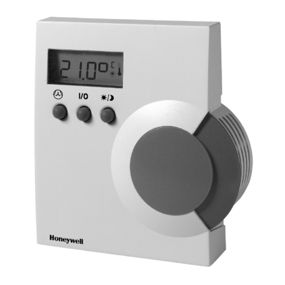
T7560A,B,C Digital Wall Module
bypass
fan override
wheel
button
button
wheel
button
button
-
-
Table 2. Controller SW requirements for powering via
terminal 5 and new LCD signaling
Fan Coil Unit
W7752
1.00.04
NOTE: A software module (ModAL module GNRSC02A) is
available to adapt the DWM to the respective Excel
20, 50, 100, 500, 600, or 800 controller, making any
further configuring obsolete. Contact your local
Honeywell distributor for further details.
DWM DISASSEMBLY
The T7560A,B,C comes packed with a sub-base that mounts
separately for ease of installation. The cover is fixed by a
latch on the underside of the unit. Remove the cover as
shown in Fig. 1 (T7560A,B) or Fig. 2 (T7560C):
1. Insert the tip of an awl or a similar narrow, pointed object
into the small hole in the latch (T7560A,B) or simply
depress the latch by hand (T7560C).
2. Pry off the cover.
Fig. 1. DWM disassembly (T7560A,B)
-
INSTALLATION INSTRUCTIONS
Hydronic
Chilled Ceiling
W7762
W7763
1.00.03
1.00.03
EN1B-0146GE51 R0308A
Advertisement

Related Manuals for Honeywell T7560A


Summary of Contents for Honeywell T7560A
- Page 1 Fig. 1 (T7560A,B) or Fig. 2 (T7560C): power wiring. 1. Insert the tip of an awl or a similar narrow, pointed object into the small hole in the latch (T7560A,B) or simply WARNING / CAUTION depress the latch by hand (T7560C).
- Page 2 Power The DWM can be powered as follows: Fig. 3. Mounting of DWM (T7560A,B shown) • T7560A: preferably via the 5 V LED input (terminal 5); via terminal 8 is also possible See Fig. 6 for T7560A,B,C mounting dimensions. •...
- Page 3 24 Vac from controller; I < 6 mA 18 Vdc (I < 2.4 mA) ... 30 Vdc (I < 10 mA) Fig. 5. Mounting cover of T7560A,B DWM Controllers with the following output ratings can be connected to terminal 5 (ratings are met by all Excel 10 controllers): •...
- Page 4 CONFIGURATION (T7560A,B) In the following, default settings are marked with an asterisk (*). After installation, the T7560A,B DWM must be configured in Setpoint Type Setting / Scale Type Setting order to perform as desired. This is done by using the buttons •...
- Page 5 T7560A,B,C DIGITAL WALL MODULES ACCESSORIES Temperature offset Temperature offset; values of 0 through 99 T7460LONJACK are valid. 50 = no change (default), 49 = -0.1 °C, 51 = +0.1 °C, etc. The T7460-LONJACK is a small board and allows easy This offset varies the LCD display value, only.
- Page 6 T7560A,B,C DIGITAL WALL MODULES Manufactured for and on behalf of the Environmental and Combustion Controls Division of Honeywell Technologies Sàrl, Ecublens, Route du Bois 37, Switzerland by its Authorized Representative: Automation and Control Solutions Honeywell GmbH Böblinger Strasse 17 71101 Schönaich...