Table of Contents
Advertisement
Quick Links
Advertisement
Table of Contents
Troubleshooting

Related Manuals for Raw Thrills Terminator Salvation


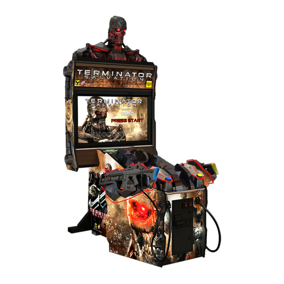
Summary of Contents for Raw Thrills Terminator Salvation
- Page 1 Setup and Operations Manual...
-
Page 2: Table Of Contents
Service Manual Table of Contents Table of Contents Safety ................................3 Product Specifications........................... 5 Setup ................................6 Adjustments, Audits and Diagnostics ......................16 Maintenance (Including critical gun maintenance procdedure) ..............34 Wiring ................................37 Parts ................................42 Troubleshooting ............................50 ®... -
Page 3: Safety
Safety PERATION Before operating game, read this manual. Failure to properly install and operate this game could result in malfunction or accident. Operate the game in accordance with the manual. RANSPORTING The cabinet is very heavy. Because the monitor is high, the cabinet is also very top-heavy. Use appropriate care when moving or transporting cabinet. - Page 4 AC line cord. Contact your local distributor. Your warranty, when applicable, lasts 60 days from your purchase date. You may not reproduce this document or any of its contents without written authorization from Raw Thrills, Inc. or Play Mechanix Inc. PECIFICATIONS copyright and other intellectual property laws protect the content, devices and design of the game and its equipment.
-
Page 5: Product Specifications
Product Specifications Electrical Power United States, international and Japan 120 VAC @ 60 Hz, 5 amps 240 VAC @ 50 Hz, 2.5 amps 100 VAC @ 50 Hz, 5 amps DC Power Fuse Guide +5 VDC 2 amp Slow Blow +12 VDC 7 amp Slow Blow Temperature... -
Page 6: Setup
Service Manual Setup Setup Unpack Materials 1. Place the shipping crates on a flat, stable surface. 2. Cut the banding straps and remove the cardboard lids. 3. Lift off the large cardboard containers surrounding the front pedestal and monitor assemblies and remove any shipping cleats. - Page 7 Check Electrical Settings 1. Verify the voltage in the nearest AC outlet. 2. Verify the AC outlet ground connection is present and working. 3. Open the back door of the monitor assembly. 4. Near the AC power transformer, verify that the voltage selector switch is set for the correct AC voltage.
- Page 8 Service Manual Setup Attach Front Pedestal to Monitor Assembly 1. Move front pedestal assembly a few inches away from the monitor assembly. ONNECTORS Ensure all connectors mate properly. If connectors do not slip in easily, do not force them. Connectors are often keyed and only connect one way. Check for correct orientation. 2.
- Page 9 Install Side Caps Side Cap Installation (front pedestal unattached to show details) 1. Hold lower left side cap against left side of monitor so that all four holes in side cap align with holes in left side wall of monitor. Note that the lower left and upper right side (Type A) caps are interchangeable.
- Page 10 Service Manual Setup Startup Game 1. Plug in line cord to AC outlet. 2. Turn the power switch to ON. Verify that the cooling fan located on the bottom back of the game is working. If not, turn off AC power and disconnect line cord. Refer to the diagnostic section of this manual. 4.
- Page 11 First Gun Calibration The Service Button Panel has four buttons, three of which can navigate the menu system. But it is easiest to navigate with a Start button and trigger/ pump. Volume TEST SERVICE Volume DOWN Service Panel TEST button enters diagnostic system.
- Page 12 Service Manual Setup 1. If the calibration screen is not already visible, press the TEST button inside the coin door to enter the Diagnostic System. 2. From the Main Menu, use a gun trigger to highlight Gun Calibration. 3. Press a Start button to enter calibration. 4.
- Page 13 9. Press Start button when finished. 10. From Main Menu, squeeze a gun trigger to cycle through choices until you reach System Tests. 11. Press a Start button to select System Tests Menu. MAIN MENU EXIT OPERATOR ADJUSTMENTS GENERAL AUDITS ONLINE MENU GUN CALIBRATION RESET MENU...
- Page 14 Service Manual Setup 17. You may use one or both guns for this test. Each gun controls a dual-track of colored dots. As you tilt each gun, the orientation of the tracks rotates as the sensors perceive the change in angle.
- Page 15 23. Squeeze the trigger to highlight the Gun Electronics Test. 24. Press the Start button to begin the test. GUN ELECTRONICS TEST LEFT GUN: FRAMES: 0 LEFT GUN: GLITCHES: 0 LEFT GUN: pBlaze_wd:0 LEFT GUN: pBlaze_pc:0 LEFT GUN: STUCK BITS:0 LEFT GUN: VERSION:0 RIGHT GUN: FRAMES: 0 RIGHT GUN: GLITCHES: 0...
-
Page 16: Adjustments, Audits And Diagnostics
Service Manual Adjustments, Audits and Diagnostics Adjustments, Audits and Diagnostics Diagnostic Menu Screens and Descriptions See First Gun Calibration for information on accessing the diagnostic menu system. Main Menu MAIN MENU EXIT OPERATOR ADJUSTMENTS GENERAL AUDITS ONLINE MENU GUN CALIBRATION RESET MENU SYSTEM INFORMATION MENU SYSTEM TESTS MENU... - Page 17 Main Menu Operator Adjustments Menu Game Adjustments Menu This controls elements of the player experience and the time the game contacts the CoinUp® server to check for software updates. GAME ADJUSTMENTS EXIT SKILL LEVEL NORMAL AVERAGE GAME LENGTH RELOAD OFFSCREEN VIOLENCE NORMAL Settings, Defaults and Choices...
- Page 18 Service Manual Adjustments, Audits and Diagnostics Main Menu Operator Adjustments Menu Coin Settings Menu This menu does not set game price, but specifies how much game credit is given for money added to the machine. The smallest accepted coin is a quarter, the typical setting for both coin values in the U.S. The DBV value is also a multiple of 25¢.
- Page 19 Main Menu Operator Adjustments Menu Player Cost Menu PLAYER COST TYPE- - - - - - - - - - - - - - -OPER FEE- - - - -COINUP FEE - - - TOTAL EXIT START COST $1.00 $0.00 $1.00 CONTINUE COST $1.00...
- Page 20 Service Manual Adjustments, Audits and Diagnostics Main Menu Operator Adjustments Menu Volume Menu Rather than requiring a manual dial or up/down buttons, all volume adjustments can be made digitally with this menu. However, during Attract Mode, pressing the Service Panel Vol + and Vol buttons only adjusts Attract Mode volume.
- Page 21 Main Menu Audits Menu Audit screens help assess game performance, find intermittent problems, decide whether to adjust game difficulty and free game award and help maximize game earnings. AUDITS EXIT GENERAL AUDITS SYSTEM AUDITS COIN AUDITS Main Menu Audits Menu General Audits GENERAL AUDITS EXIT...
- Page 22 Service Manual Adjustments, Audits and Diagnostics Main Menu Audits Menu System Audits SYSTEM AUDITS EXIT PLAY TIME 0 yr 0 dy 0:00:00 UP TIME 0 yr 0 dy 0:00:00 WATCHDOGS EXCEPTIONS BAD TRAPS Main Menu Audits Menu Coin Audits Menu COIN AUDITS EXIT TOTAL COIN 1...
- Page 23 Main Menu Gun Calibration Menu This is the same procedure described earlier in the First Calibration section. Main Menu Reset Menu RESET MENU EXIT RESET GAME AUDITS RESET HIGH SCORES RESET CREDITS RESET COIN COUNTERS RESET ADJUSTMENTS FACTORY RESET Reset Game Audits zeroes out game audits, system audits and game purchase audits. Reset High Scores zeroes out high score tables.
- Page 24 Service Manual Adjustments, Audits and Diagnostics Main Menu System Information Version List For troubleshooting purposes, this menu gives you information on the latest update of various components. VERSIONS EXIT SOUND 19.3 JAMMA 25q.H8b.Fd1.U2a R PMNET 00.00.00 SOFTWARE 00.84.00.US.D Build: Dec 8 1009 11:39:04 LEFT GUN RIGHT GUN Main Menu...
- Page 25 Main Menu System Information Telemetry Stats These tests check thermal qualities and electrical conductivity. Generally, only Core Temps 1 and 2 function. The rest should read N/A. TELEMETRY DATA EXIT SYSTEM TEMPERATURE CORE TEMP1 CORE TEMP2 TEMPERATURE STATE CPU FAN SPEED CASE FAN SPEED +3.3V: +5.0V:...
- Page 26 Service Manual Adjustments, Audits and Diagnostics Main Menu System Information Switch Telemetry Data This gives information on the time since a switch was last used in both number of games played since the switch was used and the clock time since last use. SWITCH TELEMETRY DATA EXIT GAMES NOT SEEN...
- Page 27 Main Menu System Tests Menu Gun Tests Menu Some gun test descriptions can be found in the First Calibration section earlier in this manual. GUN TESTS EXIT GUN STATUS MESSAGES GUN CAMERA TEST GUN CLICK TEST GUN ELECTRONICS TEST GUN SENSOR TEST GUN CALIBRATION Gun Status Messages displays continually updated status messages, like gun connection and IR array visibility.
- Page 28 Service Manual Adjustments, Audits and Diagnostics Main Menu System Tests Menu Online Tests Menu These tests verify components of the online system. ONLINE TESTS EXIT ETHERNET PORT TEST CARD TEST Main Menu System Tests Menu Online Tests Menu Ethernet Port Test This verifies the functioning of the Ethernet port.
- Page 29 Main Menu System Tests Menu Switch Test Menu This checks input switch performance. The activated switch is highlighted on screen. SWITCH TEST COIN1 COIN2 START 1 START 2 VOLUME DOWN VOLUME UP TEST BILL TRIGGER1 TRIGGER2 RELOAD1 RELOAD2 GRENADE1 GRENADE2 SERVICE The Switch Test menu has a unique exit procedure because it checks the switches normally used for navigation.
- Page 30 Service Manual Adjustments, Audits and Diagnostics Main Menu System Tests Menu Screen Tests Menu Color Adjustment This color bar screen of gray, yellow, cyan, green, magenta, red and blue helps identify missing colors. Missing color bars may indicate bad video RAM in the PC, or a problem with the monitor. Color bars can also help Peak the brightness and black levels Balance red, green and blue drives...
- Page 31 Main Menu System Tests Menu Screen Tests Menu Screen Adjustment Menu This crosshatch screen adjusts width and height, static convergence and purity, brightness and focus. Width and Height Adjust height and width of the crosshatch pattern until the grid fills the screen. Keep all the lines visible, though.
- Page 32 Service Manual Adjustments, Audits and Diagnostics Main Menu System Tests Menu Sound Test Menu This checks sound volume and quality. Missing sounds indicated digital flaws. Distorted sounds suggest analog flaws. Lack of sound suggests disconnected or bad cables or speakers. SOUND TESTS EXIT LEFT CHANNEL...
- Page 33 Main Menu System Tests Menu Cabinet Lamps Test This test turns the five different cabinet light lines on and off, cycling through left and right start buttons, the left and right holsters and the T-600 eyes with subwoofer. Main Menu System Tests Menu Watchdog Test This tests the Watchdog circuit, which protects the game against screen freezes (infinite loops).
- Page 34 Service Manual Maintenance Maintenance Regular Gun Maintenance Procedure -of-the-art custom-designed gun controllers. In order to maximize income potential, keep the guns in optimal working order by performing the following five- step procedure every time you empty the cash box. 1. Check the camera lens. Observe the red tinted lens at the tip of the gun to ensure it has no cracks, scratches or dirt.
- Page 35 Hard Drive Recovery Symptoms requiring hard drive recovery include File Test reports bad or missing files. Game fails to finish loading during startup. After resetting the AC power, an error is reported. You are prompted to insert a boot DVD. Erratic Game or Attract Mode.
- Page 36 Service Manual Maintenance 10. Initial software loading may take several minutes. Check progress periodically. Do not interrupt power or reset the game during recovery. 11. At some point, the game will eject Disc 1 and prompt you to insert Disc 2. Swap discs and close the tray.
-
Page 37: Wiring
Wiring I/O Board Connector Table JAMMA Edge Connector JAMMA Edge Connector Component Side Solder Side Function Wire Color Wire Color Function Ground Black Black Ground Ground Black Black Ground 5 Volts 5 Volts 5 Volts 5 Volts 12 Volts Orange Orange 12 Volts 12 Volts... - Page 38 Service Manual Wiring Cabinet Wiring Diagrams 10 T Asset Acquisition Company, LLC Page 38...
- Page 39 Page 39...
- Page 40 Service Manual Wiring Gun Wiring Diagram 10 T Asset Acquisition Company, LLC Page 40...
- Page 41 Gun Functional Block Diagram Page 41...
-
Page 42: Parts
Service Manual Parts Parts Guns and Holsters Item Description Part No. Qty. Item Description Part No. Qty. 820-00003-00 Plywood Backing Right 601-00078-01-R Plastic Holster Left 603-00060-01 Gun LED Strip 500-00045-01 Plastic Holster Right 603-00061-01 Holster Edge Glow L, R 600-00180-01 Plywood Backing Left 601-00078-01-L Gun Bracket... - Page 43 Miner General Bumper Ref. # GBA-098S 43-0995-00 #10 Flat Washer 43-0740-00 Screw 10-32 x ½ BHCS 96-1044-00 Recoil Rod Spring for Raw Thrills Rifle 43-0172-00 Screw, #2 x ½ Type B. PPH 43-0067-00 Screw, 8 x 3/8 Phil Hi-Low PH 43-0436-00 Screw #4 x ¼...
- Page 44 Service Manual Parts Guns 10 T Asset Acquisition Company, LLC Page 44...
- Page 45 Control Panel Item Description Part No. Qty. Item Description Part No. Qty. Woofer Panel 603-00059-01 Player 2 Button 702-00026-01 Woofer Grille 600-00185-01 Player 1 Plastic 600-00183-01 Woofer LED Strip 500-00044-02 Player 2 Plastic 600-00184-01 Control Panel 603-00058-01 Short LED Strip 500-00047-01 Player 1 Button 702-00019-01...
- Page 46 Service Manual Parts Monitor and Top Box Assembly Item Description Part No. Qty. Item Description Part No. Qty. Monitor cabinet 601-00074-01 Translight 606-00156-01 Marquee Cap A 603-00062-01 Top Marquee 600-00187-01 Retainer Marquee Cap B 603-00063-01 809-00004-00 Monitor Frame Assembly 809-00004-00 Speaker Grill 600-00173-01 Marquee PETG...
- Page 47 Front Pedestal Assembly Item No. Description Part No. Qty. Front Pedestal 601-00075-01 Coin Door 800-00005-00 850-00011-00 807-00002-02 AC inlet power plate 600-00076-01 Corner Brace 600-00171-01 PC Bracket 600-00189-01 Fan, 120VAC 19/15W 820-00001-00 120 mm wire fan guard 800-00001-00 Outrigger main beam 600-00170-01 Outrigger support 600-00169-01...
- Page 48 Service Manual Parts Terminator Head Item No. Description Part No. Qty. Head bracket 600-00178-01 Distortion print head 603-00064-01 Red cold cathode 702-00027-00 Eye LED 500-00048-01 LED ring 600-00246-01 10 T Asset Acquisition Company, LLC Page 48...
- Page 49 PC Boards These boards can be found mounted to the groundplane in the rear of the front pedestal. This is the view seen from standing behind the front pedestal. Item No. Description Part No. Qty. Watchdog board 520-00012-01 I/O expansion board 500-00024-01 I/O board 500-00031-01...
-
Page 50: Troubleshooting
Service Manual Troubleshooting Troubleshooting Warning: Review safety chapter before making any adjustments to game. Problem Possible Cause Solution Game will not power up. Game not plugged in Plug game into AC outlet. Game not turned on Turn on main power switch. Game fuse is blown. - Page 51 Problem Possible Cause Solution Game resets. Bad file. Run File Test. Restore hard drive. Coin meter does not click during No pulse to meter Check all wiring from meter to I/O Test. board Faulty meter Replace coin meter Exits Test Mode every 3 seconds Test button stuck in ON position Slide or toggle button off after Test Menu appears...
- Page 52 Service Manual Troubleshooting Gun Troubleshooting Note: Do not replace or swap guns while power is on. Shut AC power off before connecting or disconnecting any components. If, for some reason, guns are changed while power is on, shut off AC power and reboot after the guns are connected again.
- Page 53 Connection to CoinUp Troubleshooting ® Problem Possible Cause Solution Game has IP address and screen Firewall is blocking communication Read firewall documentation. says Server Ping Success but Test with server. Ensure configuration allows ICMP Connection screen reports Database Echo. Ping failure or File Server Ping If router has built-in firewall, check failure.
- Page 54 Service Manual Troubleshooting Cellular Connection Troubleshooting Problem Possible Cause Solution Game cannot connect to CoinUp® Poor connection between cell Check that USB connections at cell server modem and PC. modem and PC are tight. Turn off cabinet AC power. Wait 30 seconds No IP address appears under Test and reboot game.
- Page 55 Wi-Fi Connection Troubleshooting Problem Possible Cause Solution Wi-Fi Details status is Not A supported USB Wi-Fi adapter is Connect a supported Wi-Fi adapter. Connected and Adapter is Not not connected. Turn cabinet AC power off for a Found. minute and reboot. Faulty network card Call CoinUp®...
-
Page 56: Coinup ® Operation Overview
® Operation Overview Having your Terminator Salvation game connected to CoinUp® allows easy access to software updates and permits game health and earnings to be monitored via coinup.com. There are three ways to connect to CoinUp®: through an Ethernet cable, a cellular modem, or a Wi-Fi connection. - Page 57 3. Enter the password. 4. (Optional) To change login information, use the Profile tab. 5. Select locations or products to view. FCC Compliance You are solely responsible for FCC compliance on installations. Network Installation Installation Process Overview 1. Install the Internet Connection 2.
- Page 58 Service Manual CoinUp® Operation Overview 9. Press the modem to the sticky side of the Velcro® strips. Ensure that the modem bonds solidly. 10. In the kit, find the modem extender cable. 11. Connect the modem cable to a USB port on the PC. 12.
- Page 59 antenna adhesive come into contact with the cabinet. The Velcro® must separate the antenna adhesive and the cabinet. 10. Remove the adhesive protection from the free side of the Velcro® strip. 11. Mount the free side of the Velcro® strip to the roof. 12.
- Page 60 Service Manual CoinUp® Operation Overview 10. Complete Wi-Fi software setup. will not connect properly to CoinUp® until setup is successfully completed. Wi-Fi Software setup Do not install the software that comes with the Wi-Fi ARNING runs appropriate Wi-Fi software. Prepare for Setup 1.
- Page 61 Encryption Key If the encryption type is disabled/open, skip this section, because there is no key. 1. At the Enter WPA Key screen, enter access point or router WPA Key (from information gathered during preparation earlier) Select yellow < and > symbols to switch between letters, numbers and symbols. 3.
- Page 62 Service Manual CoinUp® Operation Overview If game remains in this status more than five minutes, either the network information entered was incorrect, or the game cannot communicate with the access point. 1. Reboot game and return to Wi-Fi Details again. 2.
- Page 63 4. If strength is below 3/5, reposition the cell antenna and recheck signal strength. Wi-Fi Users 1. Enter Diagnostic mode by pressing the TEST service button. 2. Select Online Menu, then select Wi-Fi Menu and Wi-Fi Details 3. Note the signal strength. More green bars is better. 4.
- Page 64 Service Manual CoinUp® Operation Overview not be able to view your collections on www.coinup.com. If you wish to reset the other game audits, go to Reset Menu and select Reset Game Audits. 5. Split collection with location as usual. CoinUp® debits your account for its portion. Pricing is subject to change without notice For certain online features, CoinUp®...
-
Page 65: Forms
Forms All forms required to setup a CoinUp® account are in this section. Photocopy the form, fill it out, then sign and fax (or mail) it to the numbers or addresses on the back cover of this manual. Authorization Agreement for Automated Payment Participating Operator Agreement Operator Registration Cell Modem Service Agreement... - Page 66 Service Manual Forms Authorization Agreement for Automated Payments financial institution named below, hereinafter called DEPOSITORY and to debit the same such account. To correct errors, I (we) authorize Play DEPOSITORY and to credit the same account. I (we) acknowledge that the origination of ACH transactions to my (our) account must comply with the provisions of U.S.
- Page 67 Participating Operator Agreement Agreement _______________________, 20____, by and between Play Mechanix, Inc., an Illinois corporation with offices at 800 Roosevelt Road, Suite D- Play Mechanix ____________________________________________________________________( In consideration of mutual promises and other valuable consideration, the parties agree as follows. 1.
- Page 68 Service Manual Forms 4. USE OF SERVICES BY OPERATOR Authorization Agreement information accurate. www.coinup.com website. Ensure that CoinUp® sponsored tournament rules and regulations are followed on location and report non-compliance or cheating immediately to Play Mechanix. Report significant malfunctions of equipment and software to Play Mechanix. The schedule of CoinUp®...
- Page 69 7. CONTENT IN THE SERVICES 7.1 You understand that all information (such as data files, written text, music, audio files or other sounds, photographs, videos or other images) which You may have access to as part of, or through your use of, the Services (all such information is Content 7.2 You should be aware that Content presented to You as part of the Services, including but not limited to advertisements in the Services and sponsored Content within the Services may be protected by intellectual property rights which are owned by...
- Page 70 Service Manual Forms and that Play Mechanix shall not disclose such information without your prior written consent. 8.6 You agree that You shall not remove, obscure or alter any proprietary rights notices (including copyright and trade mark notices) which may be affixed to or contained within the Services. 8.7 Unless You have been expressly authorized to do so in writing by Play Mechanix, You agree that in using the Services, You will not use any trade mark, service mark, trade name or logo of any company or organization in a way that is likely or intended to cause confusion about the owner or authorized user of such marks, names or logos.
- Page 71 12. EXCLUSION OF WARRANTIES 12.1 NOTHING IN THESE TERMS, INCLUDING SECTIONS 12 AND 13 OR LIABILITY FOR LOSSES WHICH MAY NOT BE LAWFULLY EXCLUDED OR LIMITED BY APPLICABLE LAW. SOME JURISDICTIONS DO NOT ALLOW THE EXCLUSION OF CERTAIN WARRANTIES OR CONDITIONS OR THE LIMITATION OR EXCLUSION OF LIABILITY FOR LOSS OR DAMAGE CAUSED BY NEGLIGENCE, BREACH OF CONTRACT OR BREACH OF IMPLIED TERMS, OR INCIDENTAL OR CONSEQUENTIAL DAMAGES.
- Page 72 Service Manual Forms PARAGRAPH 13.1 ABOVE SHALL APPLY WHETHER OR NOT PLAY MECHANIX HAS BEEN ADVISED OF OR SHOULD HAVE BEEN AWARE OF THE POSSIBILITY OF ANY SUCH LOSSES ARISING. 14. COPYRIGHT AND TRADEMARK POLICY ly with applicable international intellectual property law (including, in the United States, the Digital Millennium Copyright Act) and to terminate the accounts of infringers.
- Page 73 Operator Registration Form Before you register games, you must register an operator account! Operator Name Company Name Operator Address City, State, Zip Country Operator Phone Operator Fax Operator Email Contact Preference Email Phone Debit Account On File: No (If No, include Authorization Agreement for Automated Payments.) Mail or fax completed form to 800 Roosevelt Road, Suite D-103, Glen Ellyn, IL 60137...
- Page 74 Service Manual Forms Cell# IMEI L.O.S Operator ID# Rev. C1 ® CoinUp Cellular Terms of Service Agreement order from us connected to one of your games allowing it to communicate with the CoinUp® online network READ THIS AGREEMENT CAREFULLY BEFORE ORDERING CELLULAR SERVICE FOR YOUR CoinUp® CONNECTED GAME AND SIGNING THIS AGREEMENT.
- Page 75 solve any and all billing disputes Billing and Payment Billing takes place through your CoinUp® operator account. All methods of payment and late fees described in your CoinUp® Operator Agreement shall apply. Changes to Terms and Rates The Cellular Provider may from time to time change the rates charged for the Service. Generally, if the Cellular Provider raises the rate for Service they will allow us to discontinue the Service without fee or penalty.
- Page 76 Service Manual Forms Signatures Operator Legal Name: ___________________ _____________________ ___________________ _____________________ Name/Title: Name/Title: ___________________ _____________________ Date: Date: ___________________ _____________________ 10 T Asset Acquisition Company, LLC Page 76...
- Page 77 Contact Information For an authorized distributor near you, check the Raw Thrills website at www.rawthrills.com Contact Betson Enterprise Headquarters or your local Betson office for sales, technical information, warranty or repair. Betson can be reached at (800) 524-2343 Fax (201) 438-4837 www.betson.com CoinUp®...