Kenwood NX-5700 User Manual
Hide thumbs
Also See for NX-5700:
- Service manual (139 pages) ,
- User manual (116 pages) ,
- Common function reference (476 pages)

Related Manuals for Kenwood NX-5700


Summary of Contents for Kenwood NX-5700
-
Page 1: User Guide
NX-5000 series USER GUIDE GUIDE DE L'UTILISATEUR GUÍA DEL USUARIO The illustration shows operation panel attached models. B5A-0056-00 (K) - Page 3 The Bluetooth word mark and logo are registered trademarks owned by ® the Bluetooth SIG, Inc. and any use of such marks by JVC KENWOOD Corporation is under license. Other trademarks and trade names are those of their respective owners.
-
Page 4: Table Of Contents
THANK YOU We are grateful you have chosen KENWOOD for your Digital Transceiver applications. This User Guide covers only the basic operations of your radio. Ask your dealer for information on any customized features they may have added to your radio. For using details instruction manual, refer to the following URL. -
Page 5: Notices To The User
NOTICES TO THE USER ◆ Government law prohibits the operation of unlicensed radio transmitters within the territories under government control. ◆ Illegal operation is punishable by fine and/or imprisonment. ◆ Refer service to qualified technicians only. Safety: It is important that the operator is aware of, and understands, hazards common to the operation of any transceiver. -
Page 6: Precautions
◆ The transceiver operates in 12 V negative ground systems only! Check the battery polarity and voltage of the vehicle before installing the transceiver. ◆ Use only the supplied DC power cable or a KENWOOD optional DC power cable. ◆ Do not cut and/or remove the fuse holder on the DC power cable. -
Page 7: Terminal Descriptions
TERMINAL DESCRIPTIONS ACC (D-SUB 25 Pin Connector) Pin No. Name Description Specification — Not used COM1_RXD Serial Data Input RS-232C compatible COM1_TXD Serial Data Output Input Impedance 100 kΩ AUXI/O9 Programmable Function I/O 9 Output Impedance 100 Ω 0.5 V p-p (Typ.) Data Input Input Impedance 20 kΩ... -
Page 8: Unpacking And Checking Equipment
• KMC-35 (NX-5700/ NX-5800 only) ........ -
Page 9: Preparation
PREPARATION Various electronic equipment in your vehicle may malfunction if they are not properly protected from the radio frequency energy which is present while transmitting. Typical examples include electronic fuel injection, anti-skid braking, and cruise control. If your vehicle contains such equipment, consult the dealer for the make of vehicle and enlist his/her aid in determining if they will perform normally while transmitting. -
Page 10: Using The Microsd Memory Card
When replacing the fuse in the DC power cable, be sure to replace it with a fuse of the same value. Never replace a fuse with one that is rated with a higher value. 5 x 16 mm Self-tapping screw Flat washer Microphone Spring washer... -
Page 11: Orientation
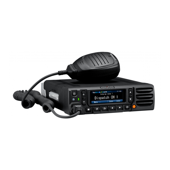
ORIENTATION OPERATION PANEL (ATTACHED PANEL OR KCH-19) a [ ] (Power) switch Press to switch the transceiver ON or OFF. b [ ] / [ ] keys Press to activate its programmable function. The default key setting is [Volume Up]/ [Volume Down]. c [ ] / [ ] keys Press to activate its programmable function. -
Page 12: Display
DISPLAY Basic Frame Function Indicator Area Main Area Key Guide Area Display Area Description Displays the various function icons, signal strength Function Indicator Area indicator, battery power indicator and clock. Display the information of the transceiver such as Main Area Channel number and Zone number. - Page 13 Indicator Description The Scrambler function is activated. The Encryption function is activated. The Encryption (AES) function is activated. The Encryption (DES) function is activated. The Talk Around function is activated. The Monitor or Squelch Off is activated. The External Speaker is activated. The External Speaker (Internal + External) is activated.
-
Page 14: Basic Operation
BASIC OPERATION SWITCHING POWER ON/ OFF Press [ ] to switch the transceiver ON. Press [ ] again to switch the transceiver OFF. ADJUSTING THE VOLUME Press the key programmed as [Volume Up] to increase the volume. Press the key programmed as [Volume Down] to decrease the volume. SELECTING A ZONE AND CHANNEL Select the desired zone and channel using the keys programmed as [Zone Up]/ [Zone Down] and [Channel Up]/ [Channel Down]. - Page 15 © 2014 JVC KENWOOD Corporation...
- Page 16 MANDATORY SAFETY INSTRUCTIONS TO INSTALLERS AND USERS • Use only manufacturer or dealer supplied antennas. • Antenna Minimum Safe Distance: 40 cm (16 inches), 50% duty Cycle. • Antenna Gain: 0 dBd referenced to a dipole. The Federal Communications Commission has adopted a safety standard for human exposure to RF (Radio Frequency) energy which is below the OSHA (Occupational Safety and Health Act) limits. • Antenna Mounting: The antenna supplied by the manufacturer or radio dealer must not be mounted at a location such that during radio transmission, any person or persons can come closer than the above indicated minimum safe distance to the antenna, i.e. 40 cm (16 inches) , 50% duty Cycle. • To comply with current FCC RF Exposure limits, the antenna must be installed at or exceeding the minimum safe distance shown above, and in accordance with the requirements of the antenna manufacturer or supplier. •...