Table of Contents
Advertisement
Quick Links
Draft - 1 Aug 08
IntelliVue TRx/TRx
for the ITS4840A/ITS4850A IntelliVue Telemetry
System
Notice (ITS4842A, TRx4841A)
These devices comply with part 15 of the FCC Rules.
Operation is subject to the following two conditions: (1)
these devices may not cause harmful interference, and
(2) these devices must accept any interference received,
including interference that may cause undesired
operation.
Notice (ITS4852A, TRx4851A)
These devices comply with part 15 of the FCC Rules,
ETSI, RSS-210, and other international radio standards
that govern operation in the ISM band. Operation is not
subject to WMTS rules.
Instructions for Use
Part Number: 4535 640 87761
Printed in the U.S.A. September 2008
First Edition
+
Transceivers
Advertisement
Table of Contents
Troubleshooting

Related Manuals for Philips IntelliVue TRx


Summary of Contents for Philips IntelliVue TRx
- Page 1 Draft - 1 Aug 08 IntelliVue TRx/TRx Transceivers for the ITS4840A/ITS4850A IntelliVue Telemetry System Notice (ITS4842A, TRx4841A) These devices comply with part 15 of the FCC Rules. Operation is subject to the following two conditions: (1) these devices may not cause harmful interference, and...
- Page 2 Reproduction in whole or in part is prohibited without the prior written consent of the copyright holder. Philips Medical Systems Nederland B.V. reserves the right to make changes in specifications and/or to discontinue any product at any time without notice or obligation and will not be liable for any consequences resulting from the use of this publication.
- Page 3 Draft - 1 Aug 08 Printing History Printing History New editions of this document will incorporate all material updated since the previous edition. Update packages can be issued between editions and contain replacement and additional pages to be merged by a revision date at the bottom of the page.
- Page 4 Draft - 1 Aug 08 About this Book About this Book This book contains operating instructions for use of the IntelliVue TRx and Transceivers as used with the IntelliVue Telemetry System with Smart- Hopping Technology. It also includes operational information for the telemetry functions of the IntelliVue Information Center.
- Page 5 Draft - 1 Aug 08 About this Book Document The following document conventions are used throughout this manual to Conventions identify specific safety and operational information. Warnings Warning Warning Warnings are information you must know to avoid injuring patients and personnel.
- Page 6 Draft - 1 Aug 08 About this Book...
-
Page 7: Table Of Contents
Draft - 1 Aug 08 Contents 1. Introducing IntelliVue Telemetry........1-1 The IntelliVue Transceiver. - Page 8 Draft - 1 Aug 08 Adjustable Sounds ............3-12 Service Sounds .
- Page 9 Draft - 1 Aug 08 6-Wire Placement ............6-17 Connecting the ECG Cable .
- Page 10 Draft - 1 Aug 08 Pulse Oximetry Measurement ........... 8-5 Pulse Tone Indication .
- Page 11 Draft - 1 Aug 08 Pairing Non-networked Devices ..........10-16 Pairing with a Direct Connection to the MP5/MP5T .
- Page 12 Draft - 1 Aug 08 TRx4851A ............12-10 SRRA .
- Page 13 Draft - 1 Aug 08 Introducing IntelliVue Telemetry This chapter introduces the IntelliVue TRx and TRx Transceivers, the patient- worn device of the IntelliVue Telemetry System with Smart-Hopping Technology. It includes the following sections: • The IntelliVue Transceiver ........1-2 •...
-
Page 14: Introducing Intellivue Telemetry
Draft - 1 Aug 08 The IntelliVue Transceiver The IntelliVue Transceiver The IntelliVue Transceiver is a patient-worn device for monitoring ECG and on adult and pediatric patients within the IntelliVue Telemetry System. The transceiver combines traditional transmitter features with communication to and from the IntelliVue Information Center. - Page 15 IntelliVue TRx M4841A M4841A EASI, 3 5 EASI, 3 5,6 EASI EASI 44 5 5 6 6 FCCID: XXXXXXXX IntelliVue TRx Transceiver - ECG Only front back IntelliVue TRx EASI M4841A EASI, 3 EASI 3 44 5 5 6 6...
-
Page 16: Intellivue Telemetry System
Draft - 1 Aug 08 IntelliVue Telemetry System IntelliVue Telemetry System The IntelliVue Telemetry System with Smart-Hopping Technology uses cellular architecture to provide two-way communication between transceivers and the IntelliVue Information Center. Smart-hopping technology dodges interference and seeks out the strongest available signal to achieve seamless connections wherever patients roam on the clinical network. -
Page 17: Smart-Hopping Technology
Draft - 1 Aug 08 IntelliVue Telemetry System Bi-directional Signal Flow in the IntelliVue Telemetry System Smart- Smart-hopping technology provides dynamic management of the RF hopping spectrum used by each transceiver. This technology allows a virtually unlimited Technology number of transceivers to operate simultaneously within the IntelliVue Telemetry System by creating a frequency-agile system that changes frequency without user involvement or awareness whenever interference occurs. - Page 18 Draft - 1 Aug 08 IntelliVue Telemetry System Smart-hopping enables the signal to avoid wireless interference. When baseline noise is low (see illustrations following), telemetry signals reside in their frequency/time slot locations. If excessive interference occurs, degrading the signal, the telemetry signal then “hops” over the interference to a location that provides optimal signal-to-noise performance.
- Page 19 Draft - 1 Aug 08 IntelliVue Telemetry System 1395 1400 1427 1432 Excessive Interference 1395 1400 1427 1432 ’Hop’ to New Frequency/Time Slot Introducing IntelliVue Telemetry...
-
Page 20: Spectrum Sharing
Draft - 1 Aug 08 IntelliVue Clinical Network Spectrum The ITS4840A IntelliVue Telemetry System operates in the Wireless Medical Sharing Telemetry Service bands (WMTS - USA only). WMTS uses radio frequency spectrum which was allocated by the FCC for medical telemetry applications, with a reduced potential for harmful interference. -
Page 21: Transceiver Use With Other Equipment
Draft - 1 Aug 08 Transceiver Use with Other Equipment • ITS4842A/ITS4852A Access Points (AP), placed within the areas with defined coverage. APs are centers for bidirectional communication between the transceivers and the Information Center. • M3150B IntelliVue Information Center for centralized monitoring. •... - Page 22 Draft - 1 Aug 08 Transceiver Use with Other Equipment Patient Remote control of monitoring parameters such as NBP, SpO , Alarm Suspend, Bedside and Relearn, as well as limited overview of waves and data are supported Monitors through Patient Bedside Monitors equipped with IntelliVue Instrument Telemetry.
-
Page 23: Product Safety
Draft - 1 Aug 08 Product Safety This chapter consolidates the safety warnings that apply to use of the IntelliVue Transceivers in a IntelliVue Clinical Network. These warnings are repeated throughout the book in context where relevant. The chapter includes the following sections: •... -
Page 24: General Safety
Draft - 1 Aug 08 General Safety General Safety Warning Warning The IntelliVue Telemetry System should not be used for primary monitoring in applications where the momentary loss of the ECG is unacceptable. Warning Warning For continued safe use of this equipment, it is necessary that the listed instructions are followed. - Page 25 Draft - 1 Aug 08 General Safety Warning Warning Do not use patient cables with detachable lead wires that have exposed male pins. Electrocution could result if these pins are plugged into AC power. Warning Warning The system is not completely immune from radio interference although it is designed to minimize interference through smart hopping.
- Page 26 Draft - 1 Aug 08 General Safety Warning Warning If the Alarms Suspend indicator on the transceiver remains illuminated after the button combination to unsuspend alarms is pressed, a transceiver malfunction may have occurred. (Alarms resume automatically after the configured alarm suspend duration, or you can resume them manually at the Information Center.) The transceiver should be replaced, and the malfunctioning unit should be sent to your service provider.
-
Page 27: Battery
Draft - 1 Aug 08 Battery Battery Warning Warning The battery door must be closed during defibrillation. Warning Warning Use Duracell Alkaline Batteries, size AA, MN 1500, 1.5V, to ensure specified performance. Outdated, mismatched, or poor-quality batteries can give unacceptable performance (e.g., insufficient Battery-Low warning time). -
Page 28: Ecg
Draft - 1 Aug 08 Warning Warning Batteries should be removed from the transceiver at the end of the battery’s useful life to prevent leakage. If battery leakage should occur, use caution in removing the battery. The leaked substance may cause eye or skin irritation. Avoid contact with skin. Clean the battery compartment according to instructions in “Chapter 11. - Page 29 Conductive parts of electrodes must not contact earth or other conductive parts. Philips recommends that you change the lead label only to reflect the physical placement of electrodes. This will ensure a match between the monitored lead and the label, and prevent any possible confusion.
-
Page 30: For Paced Patients
Draft - 1 Aug 08 ST/AR Arrhythmia For Paced Patients Warning Warning The output power of the transceiver and other sources of radio frequency energy, when used in the proximity of a pacemaker, can be sufficient to interfere with pacemaker performance. Due to the shielding effects of the body, internal pacemakers are somewhat less vulnerable than external pacemakers. - Page 31 Draft - 1 Aug 08 ST/AR Arrhythmia Warning Warning Learning If you initiate learning during ventricular rhythm, the ectopics can be incorrectly learned as the normal QRS complex. This can result in missed detection of subsequent events of V-Tach and V-Fib. Warning Warning Relearning...
-
Page 32: For Paced Patients
Draft - 1 Aug 08 ST/AR Arrhythmia For Paced Patients Warning Warning Some pace pulses can be difficult to reject. When this happens, the pulses are counted as a QRS complex, and could result in an incorrect HR and failure to detect cardiac arrest or some arrhythmias. Keep pacemaker patients under close observation. -
Page 33: St/Ar St Segment
Draft - 1 Aug 08 ST/AR ST Segment ST/AR ST Segment Warning Warning This device provides ST level change information; the clinical significance of the ST level change information should be determined by a physician. ST/AR QT Interval Warning Warning The device provides QT and QTc interval change information;... -
Page 34: Spo
Draft - 1 Aug 08 Warning Warning Always confirm Information Center observations with clinical observation of the patient before administering interventions. Warning Warning Using a sensor during MR imaging can cause severe burns. To minimize this risk, ensure that the cable is positioned so that no inductive loops are formed. - Page 35 Draft - 1 Aug 08 Warning Warning Prolonged, continuous SpO monitoring can increase the risk of changes in skin characteristics, such as irritation, reddening, blistering or pressure necrosis, particularly on patients with impaired perfusion and varying or immature skin morphology. Specific attention must be given to sensor site inspection for changes in skin quality, proper optical path alignment and attachment.
- Page 36 Draft - 1 Aug 08 Warning Warning Failure to apply a sensor properly can reduce the accuracy of the SpO measurement. Loose/Tight sensor: If a sensor is too loose, it can compromise the optical alignment or fall off. If it is too tight, for example because the application site is too large or becomes too large due to edema, excessive pressure can be applied.
- Page 37 Draft - 1 Aug 08 Warning Warning If you measure SpO on a limb that has an inflated NBP cuff, a non- pulsatile SpO technical alarm can occur. If the monitor is configured to suppress this alarm, there can be a delay of up to 60 seconds in indicating critical patient status, such as sudden pulse loss or hypoxia.
-
Page 38: Cleaning
Draft - 1 Aug 08 Cleaning Cleaning Warning Warning EO is highly explosive, toxic, and a potential occupational carcinogenic and reproductive hazard. Handle it with extreme care, following U.S. Occupational Safety and Health Administration (OSHA) standards for EO (29 CFR 1910.1047) Personnel exposure and/or room air must be monitored per OSHA standards. -
Page 39: Accessories
Accessories Accessories Warning Warning Use only Philips-approved accessories. Use of product accessories (ECG leadsets, SpO sensors, etc.) other than those specified in this manual may: - lead to patient injury - result in increased electromagnetic emissions or decreased immunity of... - Page 40 Draft - 1 Aug 08 Accessories 2-18 Product Safety...
-
Page 41: Transceiver Controls
Draft - 1 Aug 08 Transceiver Controls This chapter describes the clinical controls of the transceiver. These controls include buttons, visual and auditory indicators, ports, and safety labelling located on the front and back of the device. The chapter includes the following sections: •... -
Page 42: Transceiver Controls - Front
Transceiver Controls - Front Transceiver Controls - Front TRx4851A The labeled items in the diagram include: • Buttons (B1-B2) • Power On/Off (O1) • Indicators (I1-I4) • Labels (L1-L3) • Ports (P1-P3) IntelliVue TRx Transceiver - Front View Transceiver Controls... -
Page 43: Buttons
Draft - 1 Aug 08 Transceiver Controls - Front Buttons IntelliVue TRx M4841A EASI, 3 5,6 Callout Button Definition Telemetry Button • Depending on configuration, directs the Information Center to generate a Nurse Call alarm, remote recording, both Nurse Call alarm and recording, or none. -
Page 44: Power On/Off
Draft - 1 Aug 08 Transceiver Controls - Front Power On/ Battery Door IntelliVue TRx M4841A Callout Definition EASI, 3 5,6 to Access Power On/Off Power On/Off Insertion of batteries turns transceiver power on; removal of batteries turns power off. See “Turning the Transceiver On/Off”... -
Page 45: Labels
Valid only for recommended battery Note— type. See “Checking the Battery Power Level” on page 4-17. Labels IntelliVue TRx M4841A EASI, 3 5,6 Callout Label Definition Leadset Insertion Guide Assists in aligning the ECG cable for IntelliVue TRx different leadsets. -
Page 46: Ports
Definition IntelliVue TRx M4841A EASI, 3 5,6 ECG Leadset Port Connection for 3-, 5-, or 6-wire leadset. Sensor Port (IntelliVue TRx only) Connection for SpO sensor. See Note. Monitor/Service Port Connection for the Short-Range Radio Adapter, the cable to the TeleMon Companion Monitor and MP5 IntelliVue Patient Monitor, or to the Service Tool. -
Page 47: Transceiver Controls - Back
Transceiver Controls - Back Transceiver Controls - Back S8-S13 not shown (inside battery compartment) EASI EASI The labeled items in the diagram include: • Labels (L1-L2) • Safety symbols and other marks (S1-S14) IntelliVue TRx Transceiver - Back View Transceiver Controls... -
Page 48: Labels
Draft - 1 Aug 08 Transceiver Controls - Back Labels Callout Definition EASI EASI Electrode Placement Diagram for EASI 3 4 5 6 See “5-Wire Placement (EASI Mode)” on page 6-16. Electrode Placement Diagram for Standard ECG See “5-Wire Placement (Standard Mode)” on page 6-14. Safety Symbols &... - Page 49 PROOF) and are a TYPE CF APPLIED PART. Labels on Inside of Battery Compartment Catalog Number Use to identify the equipment during a call to the Philips Response Center. Serial Number Use to identify the equipment during a call to the Philips Response Center. Transceiver Controls...
-
Page 50: Audible Tones
Draft - 1 Aug 08 Audible Tones Callout Label Definition MAC Address of device Date of manufacture Battery Polarity Attention! See Instructions for Use. Audible Tones The transceiver produces seven different auditory information signals to inform you of measurement and transceiver conditions during normal use. Most are generated automatically. -
Page 51: Clinical Use
Draft - 1 Aug 08 Audible Tones Clinical Use Auditory Information Signal Sound How Used Sound 1 beep • Indicates successful Self-Test at power • Indicates successful SpO Spot Check measurement when measurement is initiated at the transceiver. • If the Check button is pressed, confirms that the transceiver is in contact with the Information Center (e.g., when transceiver is brought back... -
Page 52: Adjustable Sounds
Draft - 1 Aug 08 Audible Tones Auditory Information Signal Sound How Used Sound 4 beep beep • Indicates failed Self-Test at power on. • Indicates failed SpO Spot Check measurement when measurement is initiated at the transceiver. • If it sounds when the Check button is pressed, it indicates that the transceiver is not in contact with the Information Center, or in cases where the... -
Page 53: Service Sounds
Draft - 1 Aug 08 Audible Tones and pulse detection tone. The sounds can be turned off (muted) on a per patient basis in the Telemetry Setup window. Auditory Signal (sound) Function How Used Sound 1 Spot Check Announces a successful SpO Spot Check (beep) measurement. - Page 54 Draft - 1 Aug 08 Audible Tones 3-14 Transceiver Controls...
-
Page 55: Basic Operation
Draft - 1 Aug 08 Basic Operation This chapter describes the basic operation of the transceiver. It includes the following sections: • Transceiver Safety Information ......4-2 •... -
Page 56: Transceiver Safety Information
Draft - 1 Aug 08 Transceiver Safety Information Transceiver Safety Information Warning Warning The system is not completely immune from radio interference although it is designed to minimize interference through smart hopping. Sources of interference that may be a problem include failing fluorescent lights and construction equipment. -
Page 57: Turning On
Draft - 1 Aug 08 Turning the Transceiver On/Off Turning On The transceiver is powered by two AA alkaline batteries. To turn the transceiver on, insert both batteries. When batteries are inserted: 1. All indicators illuminate briefly. 2. A sequence of sounds indicates the instrument is ready for use. a. -
Page 58: Standby Mode
Draft - 1 Aug 08 Turning the Transceiver On/Off RF Auto When RF Auto Shutoff is enabled (default), the transceiver stops broadcasting a Shutoff radio signal in order to prevent interference with other transceivers in use. This condition occurs if there is no ECG signal for 10 minutes and the SpO sensor cable is not inserted in the SpO sensor port. - Page 59 Draft - 1 Aug 08 Turning the Transceiver On/Off Step Action Select the appropriate location, then select Suspend Monitoring. The message “Telemetry Standby” and location, if selected, are displayed in the sector. If the transceiver is paired with an IntelliVue Patient Note—...
-
Page 60: Briefing The Patient
Draft - 1 Aug 08 Briefing the Patient Briefing the Patient Warning Warning Patients should be instructed not to open the battery compartment while the transceiver is in use. If the Telemetry button has been configured to generate a Nurse Call, recording at the Information Center, or both, instruct the patient to use the button when needed. -
Page 61: Pouch Use
Draft - 1 Aug 08 Briefing the Patient Pouch Use The transceiver is not intended for direct contact with the patient’s skin. During normal use, the transceiver should be worn over clothing, in a pocket or, preferably, in a pouch. The carrying pouch with clear front is an appropriate means for holding the transceiver. - Page 62 Draft - 1 Aug 08 Briefing the Patient Step Action Turn the pouch so that the opening is facing downward. This protects the transceiver from fluid and debris. Secure the pouch on the patient with the upper ties around the patient’s head and arm and the lower ties around the patient’s torso.
- Page 63 Draft - 1 Aug 08 Briefing the Patient Step Action Check that the patient is comfortable wearing the pouch with transceiver. Basic Operation...
-
Page 64: Showering
The transceiver can be used to monitor a patient in the shower, but only when placed inside a Philips carrying pouch and secured on the patient as described above. The combination of the transceiver and pouch will withstand showering for up to 10 minutes. -
Page 65: Testing Transceiver Functionality
Draft - 1 Aug 08 Testing Transceiver Functionality Testing Transceiver Functionality There are two tests of IntelliVue Transceiver functionality: • Self Test - performed automatically each time the transceiver is turned on. • Status Check - initiated manually by the clinician. Self Test Warning Warning... -
Page 66: Status Check
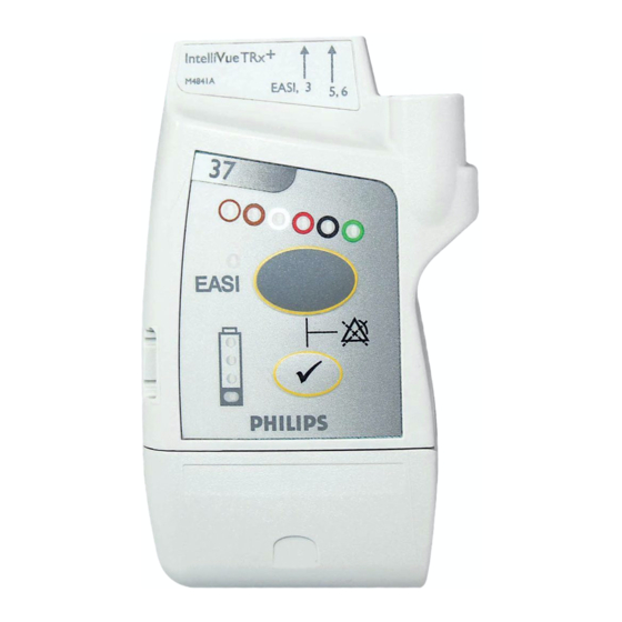
Draft - 1 Aug 08 Testing Transceiver Functionality Status You can check the status of the transceiver indicators at any time. Check Initiating a Status Check Step Action Press the button. Check The following indicators should illuminate for as long as the Check button is depressed. -
Page 67: Battery Information
Draft - 1 Aug 08 Battery Information Battery Information Battery Safety Information Warning Warning The battery door must be closed during defibrillation. Warning Warning Use Duracell Alkalaine batteries, size AA, MN 1500, 1.5V, to ensure specified performance. Outdated, mismatched, or poor-quality batteries can give unacceptable performance (e.g., insufficient Battery-Low warning time). -
Page 68: Inserting/Removing Batteries
Draft - 1 Aug 08 Battery Information Warning Warning Batteries should be removed from the transceiver at the end of the battery’s useful life to prevent leakage. If battery leakage should occur, use caution in removing the battery. The leaked substance may cause eye or skin irritation. Avoid contact with skin. Clean the battery compartment according to instructions in “Chapter 11. - Page 69 Draft - 1 Aug 08 Battery Information Inserting the Insert batteries into the transceiver using the following procedure. Batteries Step Action Open the battery compartment by swinging the compartment door counterclockwise into an open hinged position. Insert two AA 1.5V Alkaline batteries, matching the polarity with the +/- indications inside the compartment.
- Page 70 Draft - 1 Aug 08 Battery Information Removing the To remove the batteries, open the battery compartment door and push from the Batteries opening at the back of the compartment to pop the batteries out. Transceiver settings (ECG leadset type, SpO mode, volume, etc.) are retained indefinitely when the batteries are removed.
-
Page 71: Checking The Battery Power Level
Draft - 1 Aug 08 Battery Information Checking When the Check button is pressed, the battery gauge on the transceiver indicates the Battery the battery power level. It is reliable only when specified batteries (i.e., AA 1.5V Power Level Alkaline) are used. The battery gauge is also displayed in the Patient Sector at the Information Center (if configured) to enable you to closely monitor battery status, for example, after a change of shift. - Page 72 Draft - 1 Aug 08 Battery Information Battery Levels Approximate Approximate Operating Battery Gauge Battery Life* Functionality Time* Remaining Remaining 4 green indicators > 75% > 34.7 hours Normal operation 3 green indicators > 50% > 23.1 hours Normal operation 2 green indicators >...
- Page 73 Draft - 1 Aug 08 Battery Information Battery Life Battery life is dependent upon: • Condition of the batteries. • Parameters being monitored - ECG only, ECG and Spot Check SpO , or ECG and Continuous SpO • Use of the Short Range Radio Adapter (SRRA). The transceiver’s batteries power the SRRA, and under normal operating conditions, battery life may be reduced by up to 25%.
- Page 74 Draft - 1 Aug 08 Battery Information 4-20 Basic Operation...
-
Page 75: Alarms
Draft - 1 Aug 08 Alarms This chapter lists Physiologic (Patient) Alarms and Technical (Inoperative Condition) Alarms. It also describes how to pause/suspend alarms temporarily. It includes the following sections: • Alarm Indicators ......... . 5-2 •... -
Page 76: Alarm Indicators
Draft - 1 Aug 08 Alarm Indicators Alarm Indicators A description of visual and auditory information signals for patient and technical alarms on the Information Center is located in the IntelliVue Information Center Instructions for Use and the Information Center Online Help.The Information Center documentation also includes the default alarm settings and physiological alarm limit ranges. - Page 77 Draft - 1 Aug 08 Suspending/Pausing Alarms If the transceiver is connected to TeleMon or the MP5 IntelliVue Patient Monitor, alarms can be suspended only from TeleMon, and not from the Information Center. The Alarms Suspend icon on the transceiver is lit (see “Transceiver Controls - Front”...
-
Page 78: Unsuspending& Resuming Alarms
Draft - 1 Aug 08 Physiologic Alarms Unsuspending Alarms will be resumed automatically after the configured suspend duration & Resuming time. You can cancel alarm suspend manually before the configured suspend Alarms duration time has expired from the transceiver (see following directions) or from the Information Center. - Page 79 Draft - 1 Aug 08 Physiologic Alarms Warning Warning Do not rely exclusively on the audible alarm system for patient monitoring. Adjustment of alarm volume to a low level during patient monitoring may result in patient danger. Remember that the most reliable method of patient monitoring combines close personal surveillance with correct operation of monitoring equipment.
- Page 80 Draft - 1 Aug 08 Physiologic Alarms Physiologic (Patient) Alarms Alarm Text Priority Condition Source *** DESAT Very Low SpO Saturation. value below Desaturation limit Desat limit is set 10 points below Note— low limit. *** TACHY yyy > xxx Extreme Tachycardia.
- Page 81 Draft - 1 Aug 08 Physiologic Alarms Physiologic (Patient) Alarms Alarm Text Priority Condition Source ** SpO T yyy > xxx Yellow High SpO value (yyy) greater than high SpO limit (xxx). ** SpO T yyy < xxxx Yellow Low SpO value (yyy) less than low SpO limit (xxx).
- Page 82 Draft - 1 Aug 08 Physiologic Alarms Physiologic (Patient) Alarms Alarm Text Priority Condition Source * NON-SUSTAIN VT Yellow A run of Vs having a ventricular Heart ST/AR Rate greater than V-Tach limit but lasting Enhanced for less than the V-Tach Run limit. Arrhythmia * PACER NOT CAPT Yellow...
- Page 83 Draft - 1 Aug 08 Physiologic Alarms Physiologic (Patient) Alarms Alarm Text Priority Condition Source * R-ON-T PVCs Yellow For Heart Rate less than 100, a PVC with ST/AR R-R interval less than 1/3 the average Enhanced interval followed by a compensatory Arrhythmia pause of 1.25 x average R-R interval, or 2 such Vs without a compensatory pause...
-
Page 84: Technical Alarms (Inops)
Draft - 1 Aug 08 Technical Alarms (INOPs) Technical Alarms (INOPs) Technical Alarms, or INOPs (inoperative conditions), are sourced at the transceiver, the ST/AR algorithm running at the Information Center, or TeleMon Companion Monitor. They identify inoperative conditions (that is conditions where the system is not operating properly and therefore cannot measure or detect alarm conditions reliably). - Page 85 Draft - 1 Aug 08 Technical Alarms (INOPs) In the following table, technical alarms are listed alphabetically. Technical Alarms (Inoperative Conditions) Alarm Text Priority Condition What to do BATTERY LOW Soft Battery power is low. There is less than 15 minutes BATTERY LOW T of monitoring time remaining.
- Page 86 Draft - 1 Aug 08 Technical Alarms (INOPs) Technical Alarms (Inoperative Conditions) Alarm Text Priority Condition What to do CENTRAL: TELE ONLY Hard System connectivity via the For more information only. transceiver is limited (no Source - Patient Monitor alarms, only local numerics) when in companion mode and host monitor does not have...
- Page 87 Draft - 1 Aug 08 Technical Alarms (INOPs) Technical Alarms (Inoperative Conditions) Alarm Text Priority Condition What to do ECG EQUIP MALF Hard Failure of the ECG • Remove leadset. ECG EQUIP MALF T equipment or failure to Remove and re-insert calibrate ECG.
- Page 88 Draft - 1 Aug 08 Technical Alarms (INOPs) Technical Alarms (Inoperative Conditions) Alarm Text Priority Condition What to do MORE BED ALARMS Red or The monitor is associated For more information only. Yellow or with a transceiver and is Appears at Information Source - Patient Monitor Hard sending data to the...
- Page 89 Draft - 1 Aug 08 Technical Alarms (INOPs) Technical Alarms (Inoperative Conditions) Alarm Text Priority Condition What to do NO SIGNAL Hard • Transceiver is • Make sure that the outside the coverage transceiver is within Source - Information area, or the coverage area and Center •...
- Page 90 Draft - 1 Aug 08 Technical Alarms (INOPs) Technical Alarms (Inoperative Conditions) Alarm Text Priority Condition What to do T EQUIP MALF Hard Malfunction in the SpO Contact Service. equipment Source - Telemetry T ERRATIC Hard Erratic SpO Repeat measurement, measurements, often due to reposition sensor on patient, Source - Telemetry...
- Page 91 Draft - 1 Aug 08 Technical Alarms (INOPs) Technical Alarms (Inoperative Conditions) Alarm Text Priority Condition What to do T NOISY SIGNAL Hard Excessive patient Reduce movement or movements or electrical electrical noise sources. Source - Telemetry interference are causing irregular pulse patterns T NON-PULSATILE Hard...
- Page 92 Draft - 1 Aug 08 Technical Alarms (INOPs) Technical Alarms (Inoperative Conditions) Alarm Text Priority Condition What to do TELE CONFIG Hard Transceiver not supported Make sure the transceiver is UNSUPPORTED (companion mode). the correct revision. Contact Service. Source - Patient Monitor TELE DISCONNECTED Red, •...
- Page 93 Draft - 1 Aug 08 Technical Alarms (INOPs) Technical Alarms (Inoperative Conditions) Alarm Text Priority Condition What to do TELE SYNC UNSUPP Hard Incompatible MMS The MMS in use does not support synchronization of Source - Telemetry ECG and SpO2 settings between the monitor and Information Center after a transceiver has been paired.
- Page 94 Draft - 1 Aug 08 Technical Alarms (INOPs) 5-20 Alarms...
-
Page 95: Ecg Monitoring
Draft - 1 Aug 08 ECG Monitoring This chapter covers the specifics of ECG measurement. It includes the following sections: • ECG Safety Information ........6-2 •... -
Page 96: Ecg Safety Information
Conductive parts of electrodes must not contact earth or other conductive parts. Philips recommends that you change the lead label only to reflect the physical placement of electrodes. This will ensure a match between the monitored lead and the label, and prevent any possible confusion. -
Page 97: For Paced Patients
Draft - 1 Aug 08 ECG Safety Information For Paced Patients Warning Warning The output power of the transceiver and other sources of radio frequency energy, when used in the proximity of a pacemaker, can be sufficient to interfere with pacemaker performance. Due to the shielding effects of the body, internal pacemakers are somewhat less vulnerable than external pacemakers. -
Page 98: Measuring Ecg
Draft - 1 Aug 08 Measuring ECG Measuring ECG The electrocardiogram (ECG) measures the electrical activity of the heart and displays it on the Information Center as a waveform and a numeric. In order to compare measured ECG signals, the electrodes (or leadsets) are placed in standardized positions, forming so-called “leads”. - Page 99 Draft - 1 Aug 08 Measuring ECG The transceiver detects the inserted leadset type and automatically determines the ECG measurement and transmitted leads. The Leadset Insertion Guide on the device will assist you in ensuring the correct measurement during transceiver usage.
-
Page 100: Ecg Leads Monitored
Draft - 1 Aug 08 Measuring ECG There is no cardiotach within the transceiver; cardiotach analysis resides in the arrhythmia algorithm at the Information Center. Therefore, arrhythmia analysis is always turned on for telemetry patients. Arrhythmia analysis is either Basic or Enhanced, depending on the product configuration. - Page 101 Draft - 1 Aug 08 Measuring ECG these leads can be selected at the If you are using ... Information Center 5-wire (EASI mode) I, II, III, aVR, aVL, aVF, V1, V2, V3, V4, V5, In EASI mode, the sourced (raw) waves are received as: •...
- Page 102 Draft - 1 Aug 08 Measuring ECG these leads can be selected at the If you are using ... Information Center 6-wire I, II, III, aVR, aVL, aVF, V1, V2, V3, V4, V5, (Vb is not supported on V6, V7, V8, V9, V TeleMon and is only Sourced (raw) waves are received as: supported on MP5 Patient...
- Page 103 Draft - 1 Aug 08 Measuring ECG Reconstructed Reconstruction of leads from the sourced wave is defined by the calculations in Leads the following table. EASI reconstructed leads are a linear combination of all three raw EASI leads. ECG Lead 5-Wire Clinical Calculations 3-Wire...
-
Page 104: Positioning Ecg Electrodes
To protect the transceiver from damage during defibrillation, to ensure accurate ECG information, and to provide protection against signal noise and other interference, use only ECG electrodes and cables specified by Philips. Correct lead placement is always important for accurate diagnosis. Especially in the precordial leads, which are close the heart, QRS morphology can be greatly altered if an electrode is moved away from its correct location. - Page 105 Clip or shave hair from the site as necessary. • Wash site with soap and water, leaving no soap residue. Note--Philips does not recommend using ether or pure alcohol, because they dry the skin and increase the resistance. • Dry thoroughly.
-
Page 106: Locating The Fourth Intercostal Space
Draft - 1 Aug 08 Positioning ECG Electrodes Locating the Fourth Angle of Lewis Intercostal Space For accurate chest electrode placement and measurement, it is important to locate the fourth intercostal space. This can be done using the Angle of Lewis. 1. -
Page 107: 3-Wire Placement
Draft - 1 Aug 08 Positioning ECG Electrodes 3-Wire Placement Lead Placement directly below the clavicle and near the right shoulder directly below the clavicle and near the left shoulder on the left lower abdomen ECG Monitoring 6-13... -
Page 108: 5-Wire Placement (Standard Mode)
Draft - 1 Aug 08 Positioning ECG Electrodes 5-Wire Placement (Standard Mode) V4 V5 V6 Lead Placement directly below the clavicle and near the right shoulder directly below the clavicle and near the left shoulder on the left lower abdomen on the right lower abdomen on the chest, the position depends on your required lead selection. - Page 109 Draft - 1 Aug 08 Positioning ECG Electrodes Lead Placement on the fourth intercostal space at the right sternal border on the fourth intercostal space at the left sternal border midway between the V2 and V4 electrode positions on the fifth intercostal space at the left midclavicular line on the left anterior axillary line, horizontal with the V4 electrode position...
-
Page 110: 5-Wire Placement (Easi Mode)
Draft - 1 Aug 08 Positioning ECG Electrodes 5-Wire Placement (EASI Mode) Corresponds Lead to Standard Placement Lead on the lower sternum at the level of the fifth intercostal space on the left midaxillary line at the same level as the E electrode on the upper sternum on the right midaxillary line at the same level as the E electrode... -
Page 111: 6-Wire Placement
Draft - 1 Aug 08 Positioning ECG Electrodes 6-Wire 6-lead placement uses the same four limb leads as 5-lead standard placement, Placement and two precordial leads - referred to at the Information Center as Va and Vb. The default position of Va - the brown lead - is at the V2 position. The default position for Vb - the brown/white lead - is at the V5 position. - Page 112 Draft - 1 Aug 08 Positioning ECG Electrodes Lead Placement directly below the clavicle and near the left shoulder on the right lower abdomen on the left lower abdomen on the chest, the position depends on your required lead selection (see below).
- Page 113 Draft - 1 Aug 08 Positioning ECG Electrodes Lead Placement on the fourth intercostal space at the right sternal border on the fourth intercostal space at the left sternal border midway between the V2 and V4 electrode positions on the fifth intercostal space at the left midclavicular line on the left anterior axillary line, horizontal with the V4 electrode position...
- Page 114 Draft - 1 Aug 08 Positioning ECG Electrodes on the left posterior axillary line, straight line from V6 on the left midscapular line, straight line from on the left paraspinal line, straight line from V8 midway between the V1 and V4R electrode positions on the fifth intercostal space at the right midclavicular line...
-
Page 115: Connecting The Ecg Cable
Draft - 1 Aug 08 Connecting the ECG Cable Connecting the ECG Cable Caution Do not insert a leadset in the transceiver during a self-test. The leadset should be inserted either before the transceiver is powered up, or after the device has established connection with the Information Center. - Page 116 3-wire Match the arrow on the cable colored with the left arrow (labeled line EASI, 3) on the Leadset In- sertion Guide. Leadset is keyed for Note— IntelliVue TRx only one insertion position. M4841A EASI, 3 5.6 6-22 ECG Monitoring...
- Page 117 Match the arrow on the cable with the right arrow (labeled 5, colored 6) on the Leadset Insertion line Guide. l i n e IntelliVue TRx M4841A EASI, 3 5.6 5-wire EASI Match the arrow on the cable colored with the left arrow (labeled...
- Page 118 (labeled 5,6) on the Leadset Insertion colored Guide. line IntelliVue TRx M4841A EASI, 3 5.6 For 6-lead, select the lead label(s) at the Patient Window. Cable When disconnecting the leadset from the transceiver, grasp the leadset block Disconnection firmly and pull free.
-
Page 119: Verifying Electrode Connections
Draft - 1 Aug 08 Verifying Electrode Connections Verifying Electrode Connections The electrode indicators enable you to verify that the leads are available for the desired monitoring. Pressing and holding the Check button enables you to view the leadset status. During routine use of the transceiver for monitoring, all lead indicators are off. - Page 120 Draft - 1 Aug 08 Verifying Electrode Connections Step Action Expected Response: • If 3-wire cable is attached: Red, White and Black indicators illuminate, then all turn off. • If 5-wire cable in Standard mode is attached: Red, White, Black, Green & Brown indicators illuminate, then all turn off. •...
-
Page 121: Monitoring During Leads Off
Draft - 1 Aug 08 Monitoring during Leads Off During routine monitoring, the electrode indicators also notify you if one or more leads are not functioning. When a "Leads Off" condition occurs, the transceiver automatically illuminates the indicator corresponding to the missing lead. -
Page 122: Relearning
Draft - 1 Aug 08 Monitoring during Leads Off Fallback for If one of the derived EASI leads is in a technical alarm condition, a flat line is EASI displayed. After 10 seconds, the directly acquired EASI AI, AS, or ES lead, depending on which is available, is displayed with the label “ECG”. -
Page 123: Optimizing Ecg Measurement Performance
Draft - 1 Aug 08 Optimizing ECG Measurement Performance Optimizing ECG Measurement Performance Warning Warning Telemetry should not be used for primary monitoring in applications where the momentary loss of the ECG is unacceptable. No matter how good a wireless network design is, a telemetry system will always experience occasional loss of radio communications, resulting in ECG waveform dropouts. -
Page 124: Dropouts
The importance of this increases as the coverage area increases. • Frequency management is the responsibility of the hospital. Philips Medical System has no control over the RF environment in the hospital. If interference exists at the operating frequencies of the telemetry equipment, telemetry performance will be affected. - Page 125 Draft - 1 Aug 08 Optimizing ECG Measurement Performance disassociation/reassociation with the Information Center, events in the Clinical Review application can reflect loss of data for up to 1 minute in the worst case. Problem Cause Remedy Dropouts Low signal strength See “Signal Strength”...
-
Page 126: Muscle And Movement Artifact
Draft - 1 Aug 08 Optimizing ECG Measurement Performance effects and Smart-hopping enables the system to avoid most instances of interference. The 2.4 GHz ISM band used by the ITS4850A IntelliVue Telemetry System is used by many different radio technologies, (e.g. microwave ovens, wireless phones, Bluetooth devices). - Page 127 Draft - 1 Aug 08 Optimizing ECG Measurement Performance Problem Cause Remedy 60-Cycle (AC) Interference Poor electrode placement. Re-apply electrodes, using good skin preparation (see “Positioning ECG Possible non-grounded Electrodes” on page 6-10). instrument near patient. Disconnect electrical appliances near patient (one at a time) by pulling wall plugs, to determine faulty grounding.
- Page 128 Draft - 1 Aug 08 Optimizing ECG Measurement Performance Problem Cause Remedy Baseline Wander Movement of patient. Make sure patient is comfortable. Improperly applied Re-apply electrodes, using good skin electrodes. preparation (see “Positioning ECG Electrodes” on page 6-10). Check that patient cable is not pulling electrodes.
-
Page 129: St/Ar Arrhythmia
Draft - 1 Aug 08 ST/AR Arrhythmia Monitoring This chapter describes the ST/AR algorithms used for telemetry at the IntelliVue Information Center. It includes the following sections: • ST/AR Arrhythmia Algorithm ....... 7-2 •... -
Page 130: St/Ar Arrhythmia Algorithm
Draft - 1 Aug 08 ST/AR Arrhythmia Algorithm ST/AR Arrhythmia Algorithm Indications The ST/AR Arrhythmia Algorithm is indicated for use in instances where the for Use clinician decides to monitor cardiac arrhythmias of adult and pediatric patients and/or the ST segment of adult patients to gain information for treatment, monitor the adequacy of treatment, or to exclude causes of symptoms. -
Page 131: For Paced Patients
Draft - 1 Aug 08 ST/AR Arrhythmia Algorithm Warning Warning Relearning Arrhythmia relearning is initiated whenever the transceiver is powered down for one minute or longer or whenever it is directly connected/ disconnected to an IntelliVue MP5 Patient Monitor. Be sure to check your patient’s arrhythmia annotation for accuracy whenever relearn has occurred. -
Page 132: Intended Use
Draft - 1 Aug 08 ST/AR Arrhythmia Algorithm Warning Warning For paced patients who exhibit only intrinsic rhythm, the monitor can erroneously count pace pulses as QRS complexes when the algorithm first encounters them, resulting in missed detection of cardiac arrest. The risk of missing cardiac arrest can be reduced by monitoring these patients with the low heart rate limit at or slightly above the basic/demand pacemaker rate. -
Page 133: St/Ar Arrhythmia Analysis
Draft - 1 Aug 08 ST/AR Arrhythmia Algorithm ST/AR For information on arrhythmia detection, refer to the following documentation: Arrhythmia • ST/AR Algorithm - Arrhythmia Monitoring Application Note, Analysis #452298193051 • IntelliVue Information Center Instructions for Use and Online Help IntelliVue Telemetry does not have a dedicated cardiotach. - Page 134 Draft - 1 Aug 08 ST/AR Arrhythmia Algorithm Beat classification determined by the ST/AR algorithm is shown on the primary delayed wave in the Arrhythmia Analysis window at the Information Center. To access this window, select Arrhythmia Analysis from the Patient Window. The annotation requires clinical validation of the analyzed heart rhythm.
-
Page 135: St/Ar St Segment Algorithm
Draft - 1 Aug 08 ST/AR ST Segment Algorithm ST/AR ST Segment Algorithm Intended The intended use of the ST/AR ST Analysis algorithm is to monitor an adult patient’s ECG for ST segment elevation or depression and produce events/ alarms for all possible ECG leads. The ST Analysis algorithm is capable of monitoring paced and non-paced adult patients. -
Page 136: The Measurement
Draft - 1 Aug 08 ST/AR ST Segment Algorithm • ST/AR Algorithm - ST Segment Monitoring Application Note, #452298192851 • IntelliVue Information Center Instructions for Use and Online Help The ST measurement for each beat complex is the vertical difference between Measurement two measurement points. -
Page 137: Displayed St Data
Draft - 1 Aug 08 ST/AR ST Segment Algorithm • 5-wire: up to two leads if monitoring a chest and a limb lead • 5-wire: up to six leads if monitoring two limb leads • 5-wire: up to 12 leads if monitoring using EASI •... - Page 138 Draft - 1 Aug 08 ST/AR ST Segment Algorithm • You are unable to get any lead that is not noisy. • Arrhythmias such as atrial fib/flutter cause irregular baseline. • The patient is continuously ventricularly paced. • The patient has left bundle branch block. Adjusting ST The ST Setup Window enables you to adjust the ST measurement points to Measurement...
- Page 139 Draft - 1 Aug 08 ST/AR ST Segment Algorithm Step Action Adjust the J point, if necessary, by placing the cursor over the J- point button to access the adjustment arrows. Then use the arrows to position the bar at the end of the QRS complex and the beginning of the ST segment.
-
Page 140: St Alarm Settings
Draft - 1 Aug 08 ST/AR ST Segment Algorithm ST Alarm All IntelliVue Information Center alarm settings (limits and on/off status) have Settings unit default settings. The IntelliVue Information Center however, lets you set the high and low ST alarm limits for individual patients based on: •... - Page 141 Draft - 1 Aug 08 ST/AR ST Segment Algorithm Adjusting ST Make adjustments to ST alarms on the ST Alarms window at the Information Alarms Center. Step Action From the Patient Window, select the All Controls button. From the All Controls window, select the button under ST Alarms Alarm Management and Setup.
-
Page 142: St/Ar Qt Interval Algorithm
Draft - 1 Aug 08 ST/AR QT Interval Algorithm ST/AR QT Interval Algorithm Intended The intended use of the ST/AR QT/QTc analysis is for use by the physician in the risk assessment process indicated for pediatric and adult patients with and without symptoms of arrhythmia. -
Page 143: What Is Qt Interval Monitoring
Draft - 1 Aug 08 ST/AR QT Interval Algorithm What is QT Of special concern for QT monitoring is the administration of QT prolonging Interval drugs to patients identified with risk factors for Torsade de Pointe. Females, Monitoring older patients and patients with bradycardia, impaired left ventricular function (ischemia, left ventricular hypertrophy), hypokalemia and hypomagnesemia are in this increased risk category. -
Page 144: Qt Definitions
Draft - 1 Aug 08 ST/AR QT Interval Algorithm Definitions Measurement Definition QT interval in milliseconds. The QT interval is the time between the beginning of the Q wave and the end of the Twave. QTc represents the heart rate corrected QT interval. By default, the Information Center uses the Bazett correction formula to correct the QT interval for heart rate. -
Page 145: Qt Alarms
Draft - 1 Aug 08 ST/AR QT Interval Algorithm QT Alarms Alarm Definition **QTc High The QTc high limit alarm is a long yellow alarm that occurs when there are two consecutive 5 minute QTc values above the set alarm limit. **dQTc High The dQTc alarm is a long yellow alarm that occurs when the difference between the current value and... -
Page 146: How The Qt Analysis Algorithm Works
Draft - 1 Aug 08 How the QT Analysis Algorithm Works How the QT Analysis Algorithm Works The Information Center measures the QT values once every minute during startup. Subsequently, the Information Center updates the QT values every five minutes. Normal or atrial paced beats and beats with a similar morphology are averaged to form a representative waveform for further processing. - Page 147 Draft - 1 Aug 08 How the QT Analysis Algorithm Works Adjustment Description Turn QT Analysis On/Off Turn QT analysis on by clicking in the QT Analysis On check box. QT analysis is on when a checkmark displays in the check box. When the QT measurement is on, a QT status message is displayed in the QT Setup window, along with the current values for QT, QTc, dQTc...
- Page 148 Draft - 1 Aug 08 How the QT Analysis Algorithm Works Adjustment Description Select the QT Lead The QT Lead field allows you to select which leads to analyze when calculating the QT parameters. To select the desired lead by clicking on the QT Lead drop down arrow then highlighting the lead from the list that displays.
- Page 149 Draft - 1 Aug 08 How the QT Analysis Algorithm Works Adjustment Description Set the QT Baseline To quantify changes in the QTc value you can set a QTc baseline. Select the Set QT Baseline button to replace the baseline QTc value with the current QTc value.
- Page 150 Draft - 1 Aug 08 How the QT Analysis Algorithm Works Adjustment Description Turning QT Alarm On/Off There are two QT long yellow alarms (**); QTc High and dQTc High. The QTc High alarm occurs when two consecutive 5 minute QTc values are above the set alarm limit.
-
Page 151: Limitations For Qt Monitoring
Draft - 1 Aug 08 How the QT Analysis Algorithm Works Limitations Some conditions may make it difficult to achieve reliable QT monitoring. When for QT this occurs the CANNOT ANALYZE QT INOP message displays at the Monitoring Information Center, along with a QT STATUS message. Some conditions that may make reliable QT monitoring difficult include: •... - Page 152 Draft - 1 Aug 08 How the QT Analysis Algorithm Works 7-24 ST/AR Arrhythmia Monitoring...
-
Page 153: Spo Monitoring
Draft - 1 Aug 08 Monitoring This chapter provides an introduction to the SpO measurement and its application. It includes the following sections: • Safety Information ........8-2 •... -
Page 154: Spo 2 Safety Information
Draft - 1 Aug 08 Safety Information Safety Information Warning Warning Always confirm Information Center observations with clinical observation of the patient before administering interventions. Warning Warning Using a sensor during MR imaging can cause severe burns. To minimize this risk, ensure that the cable is positioned so that no inductive loops are formed. -
Page 155: Spo Information For The User
Draft - 1 Aug 08 Safety Information Warning Warning Interference leading to inaccurate measurements can be caused by: - High levels of ambient light (Hint: cover application site with opaque material) - Electromagnetic interference - Excessive patient movement and vibration. Warning Warning This equipment is not suitable for use in the presence of a flammable... - Page 156 Draft - 1 Aug 08 Safety Information Physiological SpO alarm signals will be generated at the Information Center. The SpO low limit can be set between 50 and 99% inclusive, in 1% increments. The SpO high alarm limit can be set between 51 and 100% inclusive, in 1% increments.
-
Page 157: Pulse Oximetry Measurement
Draft - 1 Aug 08 Pulse Oximetry Measurement Pulse Oximetry Measurement The ECG-SpO Transceiver supports an SpO sensor connection using Fourier Artifact Suppression Technology (FAST). The FAST algorithm overcomes many of the issues associated with traditional pulse oximetry such as sensitivity to patient movement and intense ambient light. -
Page 158: Pulse Tone Indication
Draft - 1 Aug 08 Pulse Oximetry Measurement • The amount of light passing through depends on many factors, most of which are constant, such as tissue or venous blood. However one of the factors, the blood flow in the arterioles, varies with time - because it is pulsatile. -
Page 159: Selecting A Spo Sensor
Selecting a SpO Sensor Warning Warning Use only Philips-approved accessories. Use of product accessories (ECG leadsets, SpO sensors, etc.) other than those specified in this manual may: - lead to patient injury - result in increased electromagnetic emissions or decreased immunity of... - Page 160 Draft - 1 Aug 08 Selecting a SpO Sensor Philips reusable sensors in adult, pediatric and infant models can be used, as well as Philips and Nellcor® disposable sensors. If you are using Nellcor® sensors, see the Directions for Use supplied with these sensors.
- Page 161 Draft - 1 Aug 08 Selecting a SpO Sensor The following table and chart will help you in selecting the correct sensor type. . Sensor Type When to Use Reusable You can use reusable sensors on different patients after cleaning and disinfecting them. For care and cleaning instructions, see the instructions accompanying the sensors.
- Page 162 ( lb ) ( kg ) Adult Adult Adult Adult Pedi Pedi Pedi Pedi Pedi M1192A M1191B M1194A M1901B M1903B M1904B Philips M1196A N-25 D-25 Oxisensor D-20 OxiMax Reusable Disposable sensor sensor Preferred sensor types Alternative sensor types Selecting an SpO Sensor...
-
Page 163: Applying The Sensor
Draft - 1 Aug 08 Applying the Sensor Applying the Sensor Sensor Application Safety Information Warning Warning Failure to apply a sensor properly can reduce the accuracy of the SpO measurement. Loose/Tight sensor: If a sensor is too loose, it can compromise the optical alignment or fall off. -
Page 164: Site Selection
Draft - 1 Aug 08 Applying the Sensor Site • Avoid sites with impaired perfusion, skin discoloration, excessive motion Selection or nail polish. • Avoid placing the sensor in an environment with bright lights (if necessary, cover the sensor with opaque material). •... - Page 165 Draft - 1 Aug 08 Applying the Sensor Inspect the application site every 2 to 3 hours or according to clinical practice guidelines to ensure skin integrity and correct optical alignment. If skin integrity changes, move the sensor to another site. Follow the sensor’s instructions for use, adhering to all warnings and cautions.
- Page 166 Draft - 1 Aug 08 Applying the Sensor Small Adult/ Push the sensor over the fingertip in such a way that the fingertip touches but Pediatric does not protrude from the end of the sensor. Finger sensor (M1192A) Ear Clip sensor Clip the probe onto the fleshy part of the ear lobe as shown in the diagram (M1194A) below.
-
Page 167: Connecting The Spo 2 Cable
Cable Connecting the SpO Cable Step Action Connect the sensor cable to IntelliVue TRx • Connect reusable sensors directly into the transceiver. • Connect disposable sensors into the adapter cable, then connect the adapter cable to the transceiver. Remove the protective backing. -
Page 168: Measuring Spo
Draft - 1 Aug 08 Measuring SpO Measuring SpO Warning Warning Removal of the SpO sensor during Continuous SpO monitoring results in a "No Sensor" technical alarm. There is no technical alarm for a “No Sensor” condition in Spot Check mode. Warning Warning If you measure SpO... -
Page 169: Spot Check Measurement
TeleMon because only Continuous measurement is available with this device. Step Action Attach the sensor to the patient. Connect the SpO cable to IntelliVue TRx , and check that: • The SpO sensor light turns on. • A low-pitch tone detecting each pulse is audible (unless sounds are muted). -
Page 170: Continuous Measurement
Continuous SpO monitoring. Step Action Insert the SpO cable into the IntelliVue TRx , and check that the sensor light turns on. Attach the sensor to the patient. After approximately 15 seconds, the value, with the measurement time, is displayed at the Information Center. -
Page 171: When Connected To Telemon
Draft - 1 Aug 08 Measuring SpO When When the transceiver is connected to TeleMon: Connected • The SpO measurement mode is always Continuous. to TeleMon • You can change the mode. Changes to the mode take effect when the transceiver is disconnected from TeleMon. -
Page 172: Spo Enable/Disable At Information Center
Draft - 1 Aug 08 Understanding SpO Alarms You can enable/disable SpO monitoring at the Information Center. See Enable/ “Patient Configurable Settings in Telemetry Setup” on page 9-6. Disable at When SpO is enabled, the Patient Sector and Patient Window of the Information Information Center display a “T”... - Page 173 Draft - 1 Aug 08 Understanding SpO Alarms below the Low Limit. The SpO high alarm limit can be set between 51 and 100% inclusive, in 1% increments. The delay between the physiologic alarm condition and alarm annunciation at the Information Center is <16 seconds. This means that the Information Center will generate an alarm if the averaged numeric value on the display exists beyond the alarm limit for more than a maximum of 16 seconds.
-
Page 174: Optimizing Spo 2 Measurement Performance
Draft - 1 Aug 08 Optimizing SpO Measurement Performance Optimizing SpO Measurement Performance Refer to this section on problem situations if you have difficulty getting a signal or obtaining accurate measurements. Distortion Ambient light, motion, perfusion or incorrect sensor placement can affect the accuracy of the derived measurements. - Page 175 Harsh treatment will drastically reduce the lifetime of the sensor. Moreover, Philips Medical Systems’ warranty agreement shall not apply to defects arising from improper use.
- Page 176 Draft - 1 Aug 08 Optimizing SpO Measurement Performance 8-24 Monitoring...
-
Page 177: Telemetry Functions At The Information Center & Telemon
Draft - 1 Aug 08 Telemetry Functions at the Information Center & TeleMon This chapter describes the telemetry functions at the Information Center and IntelliVue Patient Monitor, as well as the differences in transceiver operation when connected to TeleMon. It includes the sections listed below. For additional information, consult the IntelliVue Information Center Instructions for Use and TeleMon Instructions for Use. -
Page 178: Telemetry Functions At The Information Center
Draft - 1 Aug 08 Telemetry Functions at the Information Center Telemetry Functions at the Information Center Telemetry The Patient Window at the Information Center (accessed from the Patient Controls in Window control in the Patient Sector) includes controls for a number of the Patient telemetry operations. -
Page 179: Locating The Transceiver (Find Device)
Draft - 1 Aug 08 Telemetry Functions at the Information Center To Initiate a Spot Check Measurement Move the cursor over the SpO label. Then click on the Spot Check icon. There is no audio feedback at the transceiver (pulse tone or successful/ Note—... -
Page 180: Viewing Device Location In The Patient Window (Optional)
Draft - 1 Aug 08 Telemetry Functions at the Information Center To silence the sound Step Action Press and hold the Check button to turn off the sound. Remove the batteries. Viewing You can see the location of a transceiver in the Patient Window. The Device Device Location information is identified in the Patient Window by a compass icon Location in... - Page 181 Draft - 1 Aug 08 Telemetry Functions at the Information Center Using the The Device Location Client application is an optional software application that Device allows you to display and locate devices visually, using Floor Plans associated Location with your hospital’s layout. Device location history is also available. The Client application is accessible using a seperate PC’s web browser.
-
Page 182: Patient Configurable Settings In Telemetry Setup
Draft - 1 Aug 08 Telemetry Functions at the Information Center Patient The Telemetry Setup window enables you to configure the transceiver for Configurable patient-specific settings. All patient-specific settings will be reset to the unit Settings in defaults upon patient discharge. To access the window, from the Patient Telemetry Window click Telemetry Setup. -
Page 183: Patient Configurable Settings In Telemetry Setup
Draft - 1 Aug 08 Telemetry Functions at the Information Center Patient-Configurable Settings in Telemetry Setup Factory Control Function Setting Choices Default Enable/disable the SpO2 enable enable Enabled measurement at the Information disable Center or Telemon. Mode Determine the transceiver SpO Spot Check - Provides Spot Check behavior. - Page 184 Draft - 1 Aug 08 Telemetry Functions at the Information Center Patient-Configurable Settings in Telemetry Setup Factory Control Function Setting Choices Default Suppress Enable/disable the SpO enable enable INOPs algorithm to suppress sending disable with NBP technical alarms from the transceiver during an NBP measurement for 60 seconds.
-
Page 185: Unit-Configurable Settings
Draft - 1 Aug 08 Telemetry Functions at the Information Center Patient-Configurable Settings in Telemetry Setup Factory Control Function Setting Choices Default Alarm Turn SpO alarms on/off at the enable (on) enable Information Center. disable (off) Unit Settings Change current settings back to (none) last saved clinical unit settings. - Page 186 Draft - 1 Aug 08 Telemetry Functions at the Information Center Unit Settings - Telemetry Setup Factory Control Function Settings Default Telemetry Determine the Information Nurse Call - generate nurse Nurse Call Button Center response when Telemetry call alarm Button is pressed. Record - generate a recording strip Both - generate nurse call...
- Page 187 Draft - 1 Aug 08 Telemetry Functions at the Information Center Unit Settings - Telemetry Setup Factory Control Function Settings Default Suspend Sets the alarm suspend duration 1, 2, or 3 minutes 2 minutes Duration time for each assigned device on the Information Center.
- Page 188 Draft - 1 Aug 08 Telemetry Functions at the Information Center Unit Settings - Telemetry Setup Factory Control Function Settings Default Mode Determine the transceiver SpO Spot Check - Provides Spot Check behavior. manual measurements so the clinician can check as Pulse Rate and Pleth Note—...
- Page 189 Draft - 1 Aug 08 Telemetry Functions at the Information Center Unit Settings - Telemetry Setup Factory Control Function Settings Default Suppress Enable/disable the SpO enable enable Inops algorithm to detect NBP running disable with NBP and suppress sending technical alarms from the transceiver for 60 seconds.
- Page 190 Draft - 1 Aug 08 Telemetry Functions at the Information Center Unit Settings - Telemetry Setup Factory Control Function Settings Default Alarm Turn SpO alarms on/off at the enable (on) enable Information Center. disable (off) Limits Increment/decrement SpO high Limit maximum is 100. Limit 100 (adult, High alarm limit by 1 (in %).
- Page 191 Draft - 1 Aug 08 Telemetry Functions at the Information Center Unit Settings - Default Leads Factory Control Function Settings Default 5-wire, ECG3 Set the unit default lead. I, II, III, MCL, AVR, AVL, AVF, V 5-wire EASI, Set the unit default lead. I, II, III, AVR, AVL, AVF, V ECG1 5-wire EASI,...
- Page 192 Draft - 1 Aug 08 Telemetry Functions at the Information Center Unit Settings - Default Leads Factory Control Function Settings Default 6-wire, ECG4 Set the unit default lead. I, II, III, MCL, AVR, AVL, ; V lead AVF, V choice is determined by Va and Vb settings...
- Page 193 Draft - 1 Aug 08 Telemetry Functions at the Information Center Unit Settings - NBP Setup Factory Control Function Settings Default Systolic Low Increment/decrement NBP low Limit Maximum is 155 90 Adult alarm limit by 1. Limit Minimum is 28 (Adult) 70 Pediatric Limit Maximum is 255 Limit Minimum is 28 (Ped.)
-
Page 194: Rf Auto Shutoff
Draft - 1 Aug 08 Telemetry Functions at the Information Center Unit Settings - Alarms Factory Control Function Settings Default Non- Set latched/non-latched status Latched Latched arrhythmia for SpO , ST, and other non- Non-latched Yellow arrhythmia yellow alarms. Alarms Leads Off Adjust the severity level of this Cyan... -
Page 195: Transceiver Operation When Connected To Telemon
Draft - 1 Aug 08 Transceiver Operation when Connected to TeleMon Transceiver Operation when Connected to TeleMon When connected to TeleMon, the following differences in transceiver operation will be in effect. Important— The transceiver must have good batteries installed before being connected to TeleMon. -
Page 196: Spo 2 Monitoring
Draft - 1 Aug 08 Transceiver Operation when Connected to TeleMon Operation • is always in continuous mode. • Changes in SpO mode do not take effect until after the transceiver is disconnected from TeleMon. Mode settings are defined in the following table: Mode Selected at TeleMon Mode at Disconnected Transceiver... -
Page 197: Pairing Monitoring Devices
Draft - 1 Aug 08 Pairing Monitoring Devices You can display measurement data from IntelliVue TRx and TRx+ Transceivers on IntelliVue Patient Monitors. The transceiver and the monitor must be assigned to the same patient; this is called "pairing". Once paired, the ECG source is automatically detected at the Information Center. - Page 198 Draft - 1 Aug 08 This chapter describes how to pair the devices using a direct connection and a wireless, short-range radio connection, and how the devices operate in paired mode (networked and non-networked). It includes the sections listed below. For additional information on monitor operation, consult the IntelliVue Patient Monitor Instructions for Use.
-
Page 199: Device Revision Pairing Functionality
Draft - 1 Aug 08 Pairing Networked Devices Device The level of pairing functionality available is dependent on the software Revision revision of the devices in use. Refer to the following table to identify available Pairing functionality. Functionality Transceiver Patient Information Functionality Rev. -
Page 200: Pairing With A Direct Connection To The Mp5
Draft - 1 Aug 08 Pairing Networked Devices Pairing with When the transceiver, assigned to a patient sector at the Information Center, uses a Direct an interface cable to connect to an MP5 Patient Monitor, the Information Center Connection automatically pairs (if configured to do so) the two devices. Pairing using this to the MP5 method provides up to 4 ECG waves at the MP5, along with SpO measurements and a pleth wave. -
Page 201: Pairing At The Intellivue Patient Monitor
Draft - 1 Aug 08 Pairing Networked Devices When transceivers and MP5 Patient Monitors are paired directly via Important— an interface cable, your ECG source must be connected before connecting or disconnecting the interface cable to maintain synchronized alarm settings. The interface cable must be disconnected prior to unpairing the devices at the Information Center or the monitor. - Page 202 Draft - 1 Aug 08 Pairing Networked Devices Step Action Remove the protective cover from the transceiver’s monitor/service port. Position the rubber cover over the top of the SRRA. Attach the connected strap around the transceiver above the Leadset Insertion Guide.
-
Page 203: Unpairing The Monitor And Transceiver
Draft - 1 Aug 08 Pairing Networked Devices To pair the transceiver to the monitor: 1. Press the Check Button on the transceiver. The measurement selection key on the monitor will change to show the "assign telemetry" icon 2. Select the assing telemetry icon. 3. -
Page 204: Alarm Behavior (Networked)
Draft - 1 Aug 08 Pairing Networked Devices The Unpair SmartKeys and pop-up keys appear only on the monitor Note— which is directly involved in pairing. Alarm Both the IntelliVue Telemetry System and the IntelliVue Patient Monitor Behavior source alarms. The following table summarizes alarm behavior when a (Networked) transceiver is paired with an IntelliVue bedside monitor without a direct cable or short-range radio connection. - Page 205 Draft - 1 Aug 08 Pairing Networked Devices Where Initiated Effect at Bedside Effect at Information Center Silence Bedside Silences bedside alarms. Silences bedside alarms. Silences telemetry alarms if Enable Silences telemetry alarms if Enable Global Silence for Paired Beds is on at Global Silence for Paired Beds is on the Information Center.
- Page 206 Draft - 1 Aug 08 Pairing Networked Devices Where Initiated Effect at Bedside Effect at Information Center Suspend/Pause Bedside Suspends/Pauses bedside alarms. Bed Alarms Suspend/Bed Alarms Paused INOP displayed. Information Center Suspends/Pauses bedside and Suspends/Pauses bedside and telemetry alarms. telemetry alarms. Alarms Suspend/ Alarms Paused INOP displayed.
- Page 207 Draft - 1 Aug 08 Pairing Networked Devices Warning Warning If the remote Silence key in the Overview window is enabled for IntelliVue monitors connected to the Information Center, remote silencing for these beds will be enabled in other clinical units. Alarm/INOPs at The alarms and INOPs that are displayed, recorded, and stored at the the Information...
-
Page 208: Alarm Behavior (Networked With Cable Or Short-Range Radio Connection)
Draft - 1 Aug 08 Pairing Networked Devices Alarm The following table summarizes alarm behavior when a transceiver is paired Behavior with an IntelliVue MP5, MP2, or X2 bedside monitor with a direct cable or (Networked short-range radio connection. with Cable or Short-Range Radio Warning... - Page 209 Draft - 1 Aug 08 Pairing Networked Devices Where Initiated Effect at Bedside Effect at Information Center Suspend/Pause Bedside Suspends/Pauses bedside and Alarms Suspend/Alarms Paused telemetry alarms. INOP displayed. Information Center Suspends/Pauses bedside and Alarms Suspend/Alarms Paused telemetry alarms. INOP displayed. Standby Bedside Bedside and telemetry put into...
-
Page 210: Paired Device Synchronized Alarm Settings (Networked)
Draft - 1 Aug 08 Pairing Networked Devices Paired Device If the patient’s ECG is initially being measured with a patient monitor, and Synchronized then the patient is connected to the transceiver for monitoring, the Information Alarm Center will use the patient monitor settings for the transceiver. When the Settings initial ECG source is the transceiver, and then the patient is connected to the (Networked) - Page 211 Draft - 1 Aug 08 Pairing Networked Devices When transceivers and MP5 Patient Monitors are paired directly via Important— an interface cable, your ECG source must be connected before connecting or disconnecting the interface cable to maintain synchronized alarm settings. The interface cable must be disconnected prior to unpairing devices at the Information Center or the monitor.
-
Page 212: Pairing Non-Networked Devices
Draft - 1 Aug 08 Pairing Non-networked Devices Pairing Non-networked Devices Using the monitor interface cable, you can directly connect the TRx /TRx+ Transceivers to an MP5/MP5T monitor that does not have a network connection in order to transmit additional measurement data to the IntelliVue Information Center. - Page 213 Draft - 1 Aug 08 Pairing Non-networked Devices Pairing with To connect the transceiver to the monitor, perform the following steps: a Direct Connection Step Action to the MP5/ MP5T Remove the protective cover from the transceiver’s monitor/service port. Insert the interface cable into the monitor/service port. Attach the interface cable to the monitor using the port labeled with icon.
- Page 214 Draft - 1 Aug 08 Pairing Non-networked Devices Step Action Remove the protective cover from the transceiver’s monitor/service port. Position the rubber cover over the top of the SRRA. Attach the connected strap around the transceiver above the Leadset Insertion Guide.
-
Page 215: Unassigning Transceiver With Srra At The Monitor
Draft - 1 Aug 08 Pairing Non-networked Devices To pair the transceiver to the monitor: 1. Press the Check Button on the transceiver. The measurement selection key on the monitor will change to show the "assign telemetry" icon 2. Select the assing telemetry icon. 3. - Page 216 Draft - 1 Aug 08 Pairing Non-networked Devices The following table summarizes alarm behavior when a transceiver is paired with an IntelliVue bedside monitor without network connection. For detailed information, see the IntelliVue Patient Monitor Instructions for Use and the IntelliVue Information Center Instructions for Use.
-
Page 217: More Bed Alarms
Draft - 1 Aug 08 Pairing Non-networked Devices More Bed The More Bed Alarms INOP is displayed at the Information Center when a Alarms physiological alarm or INOP is generated by the bedside that is not included in the group of alarms that is transmitted to the Information Center by the transceiver. -
Page 218: Short-Range Radio Error Conditions
Draft - 1 Aug 08 Pairing Non-networked Devices Short- The following table describes error conditions that may occur when the Range transceiver is paired with the monitor (MP5, MP2 and X2 IntelliVue Patient Radio Error Monitors only) via short-range radio capability. Conditions Condition Description... - Page 219 Draft - 1 Aug 08 Pairing Non-networked Devices Condition Description Action Replace BatteryT INOP When operating wirelessly, the Insert new AA batteries in displayed at the monitor bedside monitor is no longer the transceiver. and the Information Center. providing power to the transmitter, and battery capacity is now depleted.
- Page 220 Draft - 1 Aug 08 Pairing Non-networked Devices Warning Warning When monitoring using short range-radio capability, there are numerous causes of radio interference, (e.g. microwave ovens, bluetooth devices, DECT phones, coverage area limitations) that may disrupt monitoring momentarily or for extended periods. For more information on reducing interference, see “Optimizing ECG Measurement Performance”...
-
Page 221: Maintenance, Cleaning & Troubleshooting
Draft - 1 Aug 08 Maintenance, Cleaning & Troubleshooting All installation tasks are performed by Service personnel and are described in detail in the service documentation accompanying the system. This chapter provides procedures for maintaining the equipment after installation including assigning labels for replacement transceivers, keeping the transceiver clean, and troubleshooting common problems. -
Page 222: Maintenance
Draft - 1 Aug 08 Maintenance Maintenance Basic Before beginning monitoring on a patient: Monitoring • Check for any mechanical damage. • Check all the external leads, plug-ins and accessories. • Check all the functions of the instrument which are needed to monitor the patient. - Page 223 Draft - 1 Aug 08 Maintenance Re-assigning The following instructions enable you to reassign an equipment label from a lost an Equipment device to a replacement transceiver. Label Note— If the leadset is attached during this procedure, the label assignment will fail.
-
Page 224: Cleaning And Sterilization
Draft - 1 Aug 08 Cleaning and Sterilization Step Action Select Assign Label to initiate programming of the Equipment Label into the replacement telemetry device - AND - within 10 seconds, press the Check button on the telemetry device. If 10 seconds pass without a button push, then repeat starting Note—... -
Page 225: Cleaning The Transceiver
Caution Use of abrasive cleaning materials, or disinfectants or cleaning agents not listed herein, on any part or component of the IntelliVue TRx or TRx transceiver may damage the components. See the list of unsupported cleaners in the table below. - Page 226 Draft - 1 Aug 08 Cleaning and Sterilization Cleaner Active Ingredient Cidex* Gluteraldehyde (2.4%) WipesPlus Phenylphenol (0.28%), Benzyl-p-chlorophenol Disinfecting (0.03%) Wipes TechSpray Isopropyl Alcohol General Purpose Cleaner 70% Surgical Isopropyl Alcohol, Ethyl Alcohol mixed for alcohol > Spirit Virahol Hospital Isopropyl Alcohol 70% Surface Disinfectant...
-
Page 227: Eo Sterilization
Draft - 1 Aug 08 Cleaning and Sterilization Perform the following steps to clean the transceiver of visible surface contamination. Step Action Remove the batteries and any cables or accessories. Wipe the transceiver clean by using a cloth dampened modestly with one of the approved cleaning agents listed in the table above. - Page 228 Draft - 1 Aug 08 Cleaning and Sterilization Equipment and Materials Warning Warning EO is highly explosive, toxic, and a potential occupational carcinogenic and reproductive hazard. Handle it with extreme care, following U.S. Occupational Safety and Health Administration (OSHA) standards for EO (29 CFR 1910.1047) Personnel exposure and/or room air must be monitored per OSHA standards.
- Page 229 Draft - 1 Aug 08 Cleaning and Sterilization Step Action Apply -26 inHg +/- 1 (-12.77 psig +/- .49) vacuum to the empty sterilizer chamber two times, to remove any residual EO or mois- ture. Vent the vacuum pump to the outdoors to avoid toxic hazards to personnel.
- Page 230 Draft - 1 Aug 08 Cleaning and Sterilization Step Action Extract the gas mixture from the sterilizer as follows: Warning Warning Comply with OSHA standards . Do not vent sterilizer gas to the room, but vent only outdoors or to a suitable, evacuated container, depending upon state, provincial, or country environ- mental regulations.
- Page 231 Draft - 1 Aug 08 Cleaning and Sterilization Aeration Procedure Warning Warning To avoid chemical burns and toxic effects, the equipment must be aerated after sterilization, as described. The aerator must have bacterial filters and outdoor venting. See “References” on page 11-11. Aerate the processed equipment by performing the following steps: Step Action...
- Page 232 Draft - 1 Aug 08 Cleaning and Sterilization Test Procedure Caution You must perform this test each time you put a transceiver through the EO sterilization process. This test allows you to verify that patient information for both ECG and SpO you are monitoring pulse oximetry) appear at the Information Center and at the bedside.
- Page 233 Draft - 1 Aug 08 Cleaning and Sterilization Step Action Test the transceiver: a. Put fresh batteries in the transceiver (without a leadset attached) and close the battery door Result: All six lead lights should flash, and one light should remain on. b.
-
Page 234: Troubleshooting
Draft - 1 Aug 08 Troubleshooting Troubleshooting Basic Troubleshooting For problems with... see... • ECG measurement “Optimizing ECG Measurement Performance” on page 6-29. “Using EASI Leads to Troubleshoot” on page 6- “Technical Alarms (INOPs)” on page 5-10. • measurement “Optimizing SpO Measurement Performance”... -
Page 235: Information Signals
Draft - 1 Aug 08 Troubleshooting Information If there is a connection failure within the IntelliVue Clinical Network, an Signals information signal will be generated. This information signal will be displayed in the system message area on the Information Center where the affected wireless patient monitoring device(s) (transceiver, access point, access point controller, sync unit, or router) is assigned, as well as on all other Information Centers connected to a common Database Server. - Page 236 Draft - 1 Aug 08 Troubleshooting 11-16 Maintenance, Cleaning & Troubleshooting...
-
Page 237: Safety Standards & Specifications
Draft - 1 Aug 08 Safety Standards & Specifications This chapter describes the regulatory standards that the product complies with, along with product and measurement specifications. It includes the following sections: • Regulatory Information........12-2 •... -
Page 238: Regulatory Information
EN ISO 10993-1 for Biocompatibility. The transceiver is not designed for direct contact with the patient’s skin. The accompanying pouch is the appropriate means for holding the transceiver. Authorized EU Philips Medizin Systeme Deutschland Representative Hewlett-Packard-Strasse 2 D 71034, Boeblingen Germany 12-2 Safety Standards &... -
Page 239: Safety Standards
Draft - 1 Aug 08 Regulatory Information Safety The device complies with the following safety requirements for medical Standards electrical equipment: • IEC 601-1:1988 + A1:1991 + A2:1995 General Requirements for Safety (with worldwide deviations, including U.S. deviations) • IEC 60601-1-1:2000 System Safety •... -
Page 240: System Classification
Operation is subject to the condition that this device does not cause harmful interference. Pursuant to Part 15.21 of the FCC Rules, any changes or modifications to this equipment not expressly approved by Philips Medical Systems may cause harmful radio frequency interference, and void your authority to operate this equipment. -
Page 241: Industrie Canada Compliance (Canada)
Draft - 1 Aug 08 Electromagnetic Compatibility Industrie This Class A digital apparatus complies with Canadian ICES-003. Canada Cet appareil numérique de la classe A est conforme à la norme NMB-003 du Compliance Canada. (Canada) AC Power The system is not intended for connection to the public mains as defined in Source CISPR11. - Page 242 Draft - 1 Aug 08 Electromagnetic Compatibility Warning Warning The use of accessories, transducers and cables other than those specified in the product service and user documentation can result in increased electromagnetic emissions or decreased immunity of the product. Warning Warning Short-range radio connections are subject to interruption due to interference from other radio sources in the vicinity, including microwaves,...
-
Page 243: Reducing Electromagnetic Interference
Draft - 1 Aug 08 Electromagnetic Compatibility Reducing Electromagnetic Interference The transceiver and associated accessories can be susceptible to interference from other RF energy sources and continuous, repetitive, power line bursts. Examples of other sources of RF interference are other medical electrical devices, cellular products, information technology equipment, and radio/ television transmission. -
Page 244: Battery Specifications
Draft - 1 Aug 08 Battery Specifications Battery Specifications Battery Type Equipment Specification Battery Type 2 fresh AA disposable alkaline batteries Battery Life Note— The battery life specifications listed below are based on Duracell MN 1500 batteries. Battery life for other brands may differ. Operating Mode Battery Life ECG Only... -
Page 245: Radio Specifications
Draft - 1 Aug 08 Radio Specifications Transceiver Current Operating Mode Nominal Current ECG Only 51.3 mA @ 2.4V (TRx4841A) 51.0 mA @ 2.4V (TRx4851A) ECG/SpO Continuous 116 mA @ 2.4V Radio Specifications TRx4841A Parameter Specification Frequency Ranges Bands: 1395-1400 MHz and 1427-1432 MHz Channel Spacing: 1.6 MHz RF Output Power 8 dBm +2/-3 dB (3.2 mW to 10 mW), into... -
Page 246: Trx4851A
Draft - 1 Aug 08 Radio Specifications Parameter Specification Out of Band Spurious <-41 dBm in 1 MHz bandwidth for FCC limit Emission Levels: • <= 1394 MHz, >= 1401 MHz • <= 1428 MHz, >= 1433 MHz Occupied bandwidth as <... - Page 247 Draft - 1 Aug 08 Radio Specifications Parameter Specification Modulation Type GFSK, Gaussian Frequency Shift keying (1M40Q7D) Modulation Bandwidth Typically 1.4 MHz (20 dB Bandwidth) Out of Band Spurious Meets ETSI, RS210, FCC, ARIB standards Emission Levels Safety Standards & Specifications 12-11...
-
Page 248: Srra
Draft - 1 Aug 08 Radio Specifications SRRA Parameter Specification Frequency Ranges ISM Band: 2400-2483.5MHz Radio Channel assignment 16 Radio Channel assigned, Fc= 2405 +5*(k- 11)MHz, k=11,12,…,26 Frequency Control Controlled via the bedside monitor, selects clear channel at time of install RF Output Power 0 dBm +0/-3dB (0.5 mW to 1 mW), into Antenna load. -
Page 249: Physical Specifications
Draft - 1 Aug 08 Physical Specifications Physical Specifications ECG-only Transceiver Parameter Specification Height 140 mm (5.6 in) Width 75 mm (3 in) Depth 28.5 mm (1.14 in) Weight • without batteries or • <165 g (5.8 oz) leadset • with batteries only •... -
Page 250: Srra
Draft - 1 Aug 08 Physical Specifications Parameter Specification Weight • without batteries or • <205 g (7.2 oz) leadset • with batteries only • <255 g (9.0 oz) • with batteries and 5- • <324 g (11.5 oz) wire leadset Volume 300 cm SRRA... -
Page 251: Environmental Specifications
Draft - 1 Aug 08 Environmental Specifications Environmental Specifications Parameter Specification Temperature • Operating • 0 t 37 C (32 to 99 • Storage • -40 C to 60 C (-40 to 140 F) without batteries Humidity • Operating • < 95% RH at 37 C (99 F) non-condensing •... -
Page 252: Measurement Specifications
Draft - 1 Aug 08 Measurement Specifications Measurement Specifications Parameter Specification ECG channel transmitted Leads • Channel #1 = I, II, or III • 3 electrodes • Channel #1 = II • 5 electrodes Channel #2 = III Channel #3 = MCL •... - Page 253 0.1, 0.2, 0.5 and 1.0 ms -2 to -500 mV 1.5 ms -2 to -400 mV 2 ms Philips does not claim, verify, or validate support for all available pacemakers. EMC Performance Meets Essential Performance, but may observe Limits, radiated...
-
Page 254: Spo 2
Draft - 1 Aug 08 Measurement Specifications Parameter Specification Measurement 0 to 100% Range (Calibration and Display) Accuracy See table following. Resolution Numerics - 10 seconds Averaging Note— The update rate for the SpO pulse oximetry value and pulse rate is typically 1 second. - Page 255 Draft - 1 Aug 08 Measurement Specifications Parameter Specification Wavelength Range 500 to 1000 nm Information about wavelength range can Note— be especially useful to clinicians (e.g., clinicians performing photodynamic therapy). Pulse Rate Range: 30 to 300 bpm Measurement Accuracy: +/- 2% (available only with Resolution: 1 bpm Continuous SpO...
-
Page 256: Spo Sensor Accuracy
Draft - 1 Aug 08 Measurement Specifications Sensor Accuracy Accuracy% Model (70-100% Type Description Number Range) Philips Adult Finger M1191A Reusable Sensors Adult Finger M1191AL Adult Finger M1191ANL Adult Finger* M1191T Adult Finger M1196A Adult Finger M1196T Pediatric Finger M1192A... - Page 257 Draft - 1 Aug 08 Measurement Specifications Accuracy% Model (70-100% Type Description Number Range) Philips Adult Finger M1901B Disposable Sensors Adult Finger M1902B Pediatric Finger M1903B Adult Finger M1904B Adult/Pediatric Finger M1131A Safety Standards & Specifications 12-21...
- Page 258 Disposable Sensors OxiCliq N, Adult >40 kg (not (88 lb) available from OxiCliq P, Pediatric Philips) OxiMax MAX-A, Adult >30 kg (66 lb) OxiMax MAX-AL, Adult >30 kg (>66 lb) OxiMax MAX-N, Adult >40 kg (>88 lb) OxiMax MAX-P, Pediatric 10-50 kg (22-...
-
Page 259: Accessories
This appendix lists the accessories for use with the Transceiver. Accessories are subject to change. Some accessories are not supplied by Philips. To order accessories, visit the Philips Medical Supplies website located at the following web address: http://shop.medical.philips.com, or contact your local Philips representative. -
Page 260: Transceiver Accessories
Draft - 1 Aug 08 Transceiver Accessories Transceiver Accessories Pouches Order Number Description 989803137821 Telemetry Pouch, box of 5 989803137831 Telemetry Pouch, box of 50 989803140371 Telemetry Pouch, case of 200 Protective Covers Order Number Description 989803140431 Protective Cover for Monitor/Service port (ECG-only Transceiver), package of 10 989803140451 Protective Cover for Monitor/Service port (ECG/... -
Page 261: Short Range-Radio Adapter
Draft - 1 Aug 08 ECG Accessories Short Range- Radio Order Number Description Adapter 989803158241 Short-Range Radio Adapter 989803160331 Short Range Radio Adapter Strap (1 package of 10) ECG Accessories Electrodes Order Number Description M2202A Radio Translucent Foam Electrodes, 60 packages of 5 (300 per box) 40489E Paper Tape Electrodes, 10 packages of 30 (300 per... -
Page 262: Leadsets
Draft - 1 Aug 08 ECG Accessories Leadsets Order Number Description 989803151991 AAMI 3-wire Leadset, Snap, 79 cm (30 ”) 989803151971 AAMI 3-wire Leadset, Grabber ,79 cm (30 ”) 989803152071 AAMI 5-wire Color Leadset, Snap, 79 cm (30 ”) 989803152051 AAMI 5-wire Color Leadset, Grabber, 79 cm (30 ”) 989803152151 AAMI 6-wire Color Leadset, Snap, 79 cm (30 ”) -
Page 263: Alignment Guides
Draft - 1 Aug 08 ECG Accessories Alignment Guides Order Number Description 989803140401 Single ECG Alignment Guide, package of 10 989803140411 Single ECG Alignment Guide, tethered, package of 989803140421 Double ECG Alignment Guide, package of 10 Detachable Shields Order Number Description 989803153031 3-wire Leadset Detachable Shield, package of 10... -
Page 264: Spo 2 Accessories
Philips Pediatric Finger Sensor, 1.5 m (4.9 feet) M1192T Philips Pediatric Finger Sensor, 0.45 m (1.5 feet) M1194A Philips Adult & Pediatric Ear Sensor, 1.5 m (4.9 feet) M1196A Philips Adult Finger Clip Sensor (8-pin), 3 m (9.8 feet) M1196T Philips Adult Finger Clip Sensor (9-pin), 0.90 m (2.9 feet) -
Page 265: Disposable Sensors - Single Use
Draft - 1 Aug 08 Accessories Disposable OxiCliq, OxiMax and Oxisensor II sensors are not available from Philips Note— Sensors - in the USA or Canada. In those countries, contact Nellcor Incorporated directly. Single Use Order Number Description M1901B *Philips Adult >40 kg (>88 lb) - Page 266 Draft - 1 Aug 08 Accessories Order Number Description 989803148231 Masimo LNCS ADTx Adult 989803148241 Masimo LNCS PDTx Pediatric N/A from Philips Masimo LNCS Neo-3 Adult Uses Philips M1943A or Nellcor OC-3 Adapter Cable. Accessories...
-
Page 267: Adapter Cables
Draft - 1 Aug 08 Accessories Adapter Adapter cables are not available from Philips in Canada or Japan. In Note— Cables those countries, contact Nellcor Incorporated directly. Order Number Description M1943A Adapter cable for Nellcor SpO sensor, 2 m (6.6 ft) - Page 268 Draft - 1 Aug 08 Accessories A-10 Accessories...
-
Page 269: Sales And Support Offices
Draft - 1 Aug 08 Sales and Support Offices Please call your local Philips Medical Systems sales office listed in your telephone directory or a Philips Medical Systems regional office listed below for the location of your nearest sales office. - Page 270 Draft - 1 Aug 08 Sales and Support Offices...
- Page 271 Draft - 1 Aug 08 Index ports, alarms indicators, device location 10-21 6-30 more bed alarms, dropouts (ECG), physiologic, 8-20 SpO2, 5-11 technical, measuring, testing indicators, 6-29 optimizing performance, 11-2 testing, electrodes turning off, 6-10 placement, audible tones 6-11 skin prep, 3-10 definitions, 12-5...
- Page 272 Draft - 1 Aug 08 self-test alarm indicators, noise 11-15 service log, 6-32 eliminating, shower Nurse Call 4-10, 12-4 transceiver use in, on/off, 6-31 signal strength, 6-11 skin prep, on/off, smart hopping, operation, sounds ordering information 3-10 see audible tones, ECG supplies, specifications SpO2 supplies,...
- Page 273 Draft - 1 Aug 08 standby mode, suspend alarms, symbols, system messages 11-15 see information signals, Telemetry Setup, TeleMon NBP measurement with, 8-19, 9-20 SpO2 measurement modes, 1-9, 9-19 transceiver use with, testing alarm indicators, alarms, 4-12 status check, transceiver controls, models, 6-32, 11-14...
- Page 274 Draft - 1 Aug 08 Index-4...