Table of Contents
Advertisement
IntelliVue TRx/TRx
for the ITS4840A/ITS4850A IntelliVue Telemetry
System
Notice (ITS4840A)
This system complies with part 15 of the FCC Rules.
Operation is subject to the condition that this device
does not cause harmful interference.
Operation of this equipment in the United States
requires the prior coordination with a frequency
coordinator designated by the Federal Communications
Commission (FCC) for the Wireless Medical Telemetry
Service (WMTS).
Notice (ITS4850A)
This system complies with part 15 of the FCC Rules,
ETSI, RS-210, and other international radio standards
that govern operation in the ISM band. Operation is not
subject to WMTS rules.
Instructions for Use
Part Number: M4841-9001J
Printed in the U.S.A. December 2006
First Edition
+
Transceivers
Advertisement
Table of Contents
Troubleshooting

Related Manuals for Philips IntelliVue TRx


Summary of Contents for Philips IntelliVue TRx
- Page 1 IntelliVue TRx/TRx Transceivers for the ITS4840A/ITS4850A IntelliVue Telemetry System Notice (ITS4840A) This system complies with part 15 of the FCC Rules. Operation is subject to the condition that this device does not cause harmful interference. Operation of this equipment in the United States...
- Page 2 Rights Reserved. Reproduction in whole or in part is prohibited without the prior written consent of the copyright holder. Philips Medical Systems Nederland B.V. reserves the right to make changes in specifications and/or to discontinue any product at any time without notice or obligation and will not be liable for any consequences resulting from the use of this publication.
- Page 3 IntelliVue MP5 Patient Monitor, Revision E.00 About this Book This book contains operating instructions for use of the IntelliVue TRx and Transceivers as used with the IntelliVue Telemetry System with Smart- Hopping Technology. It also includes operational information for the telemetry functions of the IntelliVue Information Center.
- Page 4 About this Book • IntelliVue MP5 Patient Monitor Instructions for Use For preventive maintenance, repair, and test methods for verification of device performance, refer to the IntelliVue Telemetry System Service Kit.
- Page 5 About this Book Document The following document conventions are used throughout this manual to Conventions identify specific safety and operational information. Warnings Warning Warning Warnings are information you must know to avoid injuring patients and personnel. Cautions Caution Cautions are information you must know to avoid damaging your equipment and software.
- Page 6 About this Book...
-
Page 7: Table Of Contents
Contents 1. Introducing IntelliVue Telemetry........1-1 The IntelliVue Transceiver. - Page 8 Adjustable Sounds ............3-12 Service Sounds .
- Page 9 6-Wire Placement ............6-18 Connecting the ECG Cable .
- Page 10 When Connected to TeleMon ..........8-17 When Connected to the MP5 .
- Page 11 Indications for Use ............12-2 Rx .
- Page 12 Adapter Cables ............A-7 Monitor Interface Cable .
- Page 13 Introducing IntelliVue Telemetry This chapter introduces the IntelliVue TRx and TRx Transceivers, the patient- worn device of the IntelliVue Telemetry System with Smart-Hopping Technology. It includes the following sections: • The IntelliVue Transceiver ........1-2 •...
-
Page 14: Introducing Intellivue Telemetry
The IntelliVue Transceiver The IntelliVue Transceiver The IntelliVue Transceiver is a patient-worn device for monitoring ECG and on adult and pediatric patients within the IntelliVue Telemetry System. The transceiver combines traditional transmitter features with communication to and from the IntelliVue Information Center. Transceiver •... - Page 15 IntelliVue TRx M4841A M4841A EASI, 3 5 EASI, 3 5,6 EASI EASI 44 5 5 6 6 FCCID: XXXXXXXX IntelliVue TRx Transceiver - ECG Only front back IntelliVue TRx EASI M4841A EASI EASI, 3 3 44 5 5 6 6...
-
Page 16: Intellivue Telemetry System
IntelliVue Telemetry System IntelliVue Telemetry System The IntelliVue Telemetry System with Smart-Hopping Technology uses cellular architecture to provide two-way communication between transceivers and the IntelliVue Information Center. Smart-hopping technology dodges interference and seeks out the strongest available signal to achieve seamless connections wherever patients roam on the clinical network. -
Page 17: Smart-Hopping Technology
IntelliVue Telemetry System Bi-directional Signal Flow in the IntelliVue Telemetry System Smart- Smart-hopping technology provides dynamic management of the RF hopping spectrum used by each transceiver. This technology allows a virtually unlimited Technology number of transceivers to operate simultaneously within the IntelliVue Telemetry System by creating a frequency-agile system that changes frequency without user involvement or awareness whenever interference occurs. - Page 18 IntelliVue Telemetry System Smart-hopping enables the signal to avoid wireless interference. When baseline noise is low (see illustrations following), telemetry signals reside in their frequency/time slot locations. If excessive interference occurs, degrading the signal, the telemetry signal then “hops” over the interference to a location that provides optimal signal-to-noise performance.
- Page 19 IntelliVue Telemetry System Excessive Interference ’Hop’ to New Frequency/Time Slot Introducing IntelliVue Telemetry...
-
Page 20: Spectrum Sharing
IntelliVue Clinical Network Spectrum The ITS4840A IntelliVue Telemetry System operates in the Wireless Medical Sharing Telemetry Service bands (WMTS - USA only). WMTS uses radio frequency spectrum which was allocated by the FCC for medical telemetry applications, with a reduced potential for harmful interference. Although WMTS is managed by a frequency coordination process, this coordination and licensing does not grant the user an exclusive right to the spectrum on which their system operates, and is subject to the terms and conditions of the FCC license. -
Page 21: Transceiver Use With Other Equipment
Transceiver Use with Other Equipment between the transceivers and the Information Center. • M3150B IntelliVue Information Center for centralized monitoring. • M3154A IntelliVue Database Server (optional) for centralized data management. • M2636C TeleMon Companion Monitor (optional) for local alarms, NBP measurement, and bedside display of patient data. - Page 22 Transceiver Use with Other Equipment Patient Remote control of monitoring parameters such as NBP, SpO , Alarm Suspend, Bedside and Relearn, as well as limited overview of waves and data are supported Monitors through Patient Bedside Monitors equipped with a bi-directional radio interface. Please refer to the Instructions for Use for the specific Patient Monitor for operating information.
-
Page 23: Product Safety
Product Safety This chapter consolidates the safety warnings that apply to use of the IntelliVue Transceivers in a IntelliVue Clinical Network. These warnings are repeated throughout the book in context where relevant. The chapter includes the following sections: • General Safety..........2-2 •... -
Page 24: General Safety
General Safety General Safety Warning Warning The IntelliVue Telemetry System should not be used for primary monitoring in applications where the momentary loss of the ECG is unacceptable. Warning Warning For continued safe use of this equipment, it is necessary that the listed instructions are followed. - Page 25 General Safety Warning Warning Do not use patient cables with detachable lead wires that have exposed male pins. Electrocution could result if these pins are plugged into AC power. Warning Warning The system is not completely immune from radio interference although it is designed to minimize interference through smart hopping.
- Page 26 General Safety Warning Warning If the Alarms Suspend indicator on the transceiver remains illuminated after the button combination to unsuspend alarms is pressed, a transceiver malfunction may have occurred. (Alarms resume automatically after the configured alarm suspend duration, or you can resume them manually at the Information Center.) The transceiver should be replaced, and the malfunctioning unit should be sent to your service provider.
-
Page 27: Battery
Battery Battery Warning Warning The battery door must be closed during defibrillation. Warning Warning Use Duracell Alkaline Batteries, size AA, MN 1500, 1.5V, to ensure specified performance. Outdated, mismatched, or poor-quality batteries can give unacceptable performance (e.g., insufficient Battery-Low warning time). -
Page 28: Ecg
Warning Warning Batteries should be removed from the transceiver at the end of the battery’s useful life to prevent leakage. If battery leakage should occur, use caution in removing the battery. The leaked substance may cause eye or skin irritation. Avoid contact with skin. Clean the battery compartment according to instructions in “Chapter 11. - Page 29 Conductive parts of electrodes must not contact earth or other conductive parts. Philips recommends that you change the lead label only to reflect the physical placement of electrodes. This will ensure a match between the monitored lead and the label, and prevent any possible confusion.
-
Page 30: For Paced Patients
ST/AR Arrhythmia For Paced Patients Warning Warning The output power of the transceiver and other sources of radio frequency energy, when used in the proximity of a pacemaker, can be sufficient to interfere with pacemaker performance. Due to the shielding effects of the body, internal pacemakers are somewhat less vulnerable than external pacemakers. - Page 31 ST/AR Arrhythmia Warning Warning Learning If you initiate learning during ventricular rhythm, the ectopics can be incorrectly learned as the normal QRS complex. This can result in missed detection of subsequent events of V-Tach and V-Fib. Warning Warning Relearning Arrhythmia relearning is initiated whenever the transceiver is powered down for one minute or longer or whenever it is directly connected/ disconnected to an IntelliVue MP5 Patient Monitor.
-
Page 32: For Paced Patients
ST/AR Arrhythmia For Paced Patients Warning Warning Some pace pulses can be difficult to reject. When this happens, the pulses are counted as a QRS complex, and could result in an incorrect HR and failure to detect cardiac arrest or some arrhythmias. Keep pacemaker patients under close observation. -
Page 33: St/Ar St Segment
ST/AR ST Segment Warning Warning It is possible that pacemaker pulses will not be detected when the ECG analog output of a defibrillator is plugged into a bedside monitor. This can result in the arrhythmia algorithm’s failure to detect pacemaker non- capture or asystole. - Page 34 Warning Warning Do not use disposable sensors on patients who exhibit allergic reactions to the adhesive. Warning Warning Prolonged, continuous SpO monitoring can increase the risk of changes in skin characteristics, such as irritation, reddening, blistering or pressure necrosis, particularly on patients with impaired perfusion and varying or immature skin morphology.
- Page 35 Warning Warning Failure to apply a sensor properly can reduce the accuracy of the SpO measurement. Loose/Tight sensor: If a sensor is too loose, it can compromise the optical alignment or fall off. If it is too tight, for example because the application site is too large or becomes too large due to edema, excessive pressure can be applied.
-
Page 36: Cleaning
Cleaning Warning Warning Removal of the SpO sensor during Continuous SpO monitoring results in a "No Sensor" technical alarm. Silencing this technical alarm turns the measurement off. There is no technical alarm for a “No Sensor” condition in Spot Check mode. Warning Warning This equipment is not suitable for use in the presence of a flammable... - Page 37 Cleaning Warning Warning Comply with OSHA standards . Do not vent sterilizer gas to the room, but vent only outdoors or to a suitable, evacuated container, depending upon state, provincial, or country environmental regulations. (If the mixture is captured, it can be separated commercially and the component gases re- used.) * See “References”...
-
Page 38: Accessories
Accessories Accessories Warning Warning Use only Philips-approved accessories. Use of product accessories (ECG leadsets, SpO sensors, etc.) other than those specified in this manual may: - lead to patient injury - result in increased electromagnetic emissions or decreased immunity of... -
Page 39: Transceiver Controls
Transceiver Controls This chapter describes the clinical controls of the transceiver. These controls include buttons, visual and auditory indicators, ports, and safety labelling located on the front and back of the device. The chapter includes the following sections: • Transceiver Controls - Front....... . . 3-2 •Buttons. -
Page 40: Transceiver Controls - Front
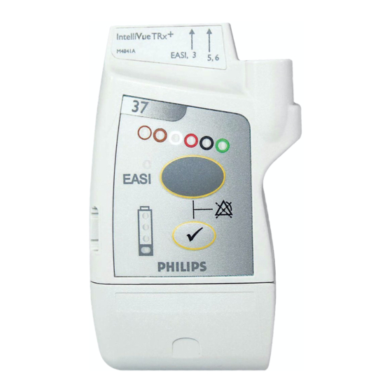
Transceiver Controls - Front Transceiver Controls - Front TRx4851A The labeled items in the diagram include: • Buttons (B1-B2) • Power On/Off (O1) • Indicators (I1-I4) • Labels (L1-L3) • Ports (P1-P3) IntelliVue TRx Transceiver - Front View Transceiver Controls... -
Page 41: Buttons
Transceiver Controls - Front Buttons IntelliVue TRx M4841A EASI, 3 5,6 Callout Button Definition Telemetry Button • Depending on configuration, directs the Information Center to generate a Nurse Call alarm, remote recording, both Nurse Call alarm and recording, or none. See “Telemetry Functions at the Information... -
Page 42: Power On/Off
Transceiver Controls - Front Power On/ Battery Door IntelliVue TRx Callout Definition M4841A EASI, 3 5,6 to Access Power On/Off Power On/Off Insertion of batteries turns transceiver power on; removal of batteries turns power off. See “Turning the Transceiver On/Off” on page 4-2. -
Page 43: Labels
Valid only for recommended battery Note— type. See “Checking the Battery Power Level” on page 4-16. Labels IntelliVue TRx M4841A EASI, 3 5,6 Callout Label Definition Leadset Insertion Guide Assists in aligning the ECG cable for IntelliVue TRx different leadsets. -
Page 44: Ports
Definition IntelliVue TRx M4841A EASI, 3 5,6 ECG Leadset Port Connection for 3-, 5-, or 6-wire leadset. Sensor Port (IntelliVue TRx only) Connection for SpO sensor. See Note. TeleMon/Service Port Connection for cable to the TeleMon Companion Monitor, MP5 IntelliVue Patient Monitor, or to the Service Tool. See Note. -
Page 45: Transceiver Controls - Back
Transceiver Controls - Back Transceiver Controls - Back S8-S13 not shown (inside battery compartment) EASI EASI The labeled items in the diagram include: • Labels (L1-L2) • Safety symbols and other marks (S1-S13) IntelliVue TRx Transceiver - Back View Transceiver Controls... -
Page 46: Labels
Transceiver Controls - Back Labels Callout Definition EASI EASI Electrode Placement Diagram for EASI 3 4 5 6 See “5-Wire Placement (EASI Mode)” on page 6-16. Electrode Placement Diagram for Standard ECG See “5-Wire Placement (Standard Mode)” on page 6-14. Safety Symbols &... - Page 47 PART. Labels on Inside of Battery Compartment Catalog Number Use to identify the equipment during a call to the Philips Response Center. Serial Number Use to identify the equipment during a call to the Philips Response Center. MAC Address of device...
-
Page 48: Audible Tones
Audible Tones Callout Label Definition Date of manufacture Battery Polarity Attention! See Instructions for Use. Audible Tones The transceiver produces six different auditory information signals to inform you of measurement and transceiver conditions during normal use. Most are generated automatically. 3-10 Transceiver Controls... -
Page 49: Clinical Use
Audible Tones Clinical Use Auditory Information Signal Sound How Used Sound 1 beep • Indicates successful Self-Test at power • Indicates successful SpO Spot Check measurement when measurement is initiated at the transceiver. • If the Check button is pressed, confirms that the transceiver is in contact with the Information Center (e.g., when transceiver is brought back into range). -
Page 50: Adjustable Sounds
Audible Tones Auditory Information Signal Sound How Used Sound 5 beep beep Indicates transceiver is out of range or not every 5 associated with a sector. Sound stops when seconds contact is re-established with the Information Center, or it can be silenced by pressing the Check button for six seconds. -
Page 51: Service Sounds
Audible Tones Service Two additional sounds that you may hear occur during the labelling of Sounds transceiver devices within the IntelliVue Clinical Network. The volume of these sounds is not adjustable, and cannot be turned off. See “Label Assignment for Replacement Transceiver”... - Page 52 Audible Tones 3-14 Transceiver Controls...
-
Page 53: Basic Operation
Basic Operation This chapter describes the basic operation of the transceiver. It includes the following sections: • Transceiver Safety Information ......4-2 •... -
Page 54: Transceiver Safety Information
Transceiver Safety Information Transceiver Safety Information Warning Warning The system is not completely immune from radio interference although it is designed to minimize interference through smart hopping. Sources of interference that may be a problem include failing fluorescent lights and construction equipment. -
Page 55: Turning The Transceiver Off
Turning the Transceiver On/Off c. cessation of sounds, indicating a successful association with the Information Center. Sounds at Successful Start-up Transceiver Transceiver Transceiver performs searches for connected self-test Information with Center Information Center Insert batteries One beep Two beeps Beeping stops Test passed every 5 sec- onds... -
Page 56: Standby Mode
Turning the Transceiver On/Off To restart monitoring, insert batteries (if needed), attach leads to the patient, insert the SpO sensor cable in the SpO sensor port and press the Check button to verify association with the Information Center. This feature must be enabled by your service provider. Standby Standby mode is used to temporarily suspend monitoring at the Information Mode... - Page 57 Turning the Transceiver On/Off Step Action Select the appropriate location, then select Suspend Monitoring. The message “Telemetry Standby” and location, if selected, are displayed in the sector. If the transceiver is paired with an IntelliVue Patient Note— Monitor, monitoring will be suspended at both the transceiver and the IntelliVue Patient Monitor as well as at the Information Center.
-
Page 58: Briefing The Patient
Briefing the Patient Briefing the Patient Warning Warning Patients should be instructed not to open the battery compartment while the transceiver is in use. If the Telemetry button has been configured to generate a Nurse Call, recording at the Information Center, or both, instruct the patient to use the button when needed. -
Page 59: Pouch Use
Briefing the Patient Pouch Use The transceiver is not intended for direct contact with the patient’s skin. During normal use, the transceiver should be worn over clothing, in a pocket or, preferably, in a pouch. The carrying pouch with clear front is an appropriate means for holding the transceiver. - Page 60 Briefing the Patient Step Action Turn the pouch so that the opening is facing downward. This protects the transceiver from fluid and debris. Secure the pouch on the patient with the upper ties around the patient’s head and arm and the lower ties around the patient’s torso.
- Page 61 Briefing the Patient Step Action Check that the patient is comfortable wearing the pouch with transceiver. Basic Operation...
-
Page 62: Showering
The transceiver can be used to monitor a patient in the shower, but only when placed inside a Philips carrying pouch and secured on the patient as described above. The combination of the transceiver and pouch will withstand showering for up to 10 minutes. -
Page 63: Testing Transceiver Functionality
Testing Transceiver Functionality Testing Transceiver Functionality There are two tests of IntelliVue Transceiver functionality: • Self Test - performed automatically each time the transceiver is turned on. • Status Check - initiated manually by the clinician. Self Test Warning Warning Do not use the transceiver for patient monitoring if it fails the Power On Self Test. -
Page 64: Status Check
Testing Transceiver Functionality Status You can check the status of the transceiver indicators at any time. Check Initiating a Status Check Step Action Press the button. Check The following indicators should illuminate for as long as the Check button is depressed. •... -
Page 65: Battery Information
Battery Information Battery Information Battery Safety Information Warning Warning The battery door must be closed during defibrillation. Warning Warning Use Duracell Alkalaine batteries, size AA, MN 1500, 1.5V, to ensure specified performance. Outdated, mismatched, or poor-quality batteries can give unacceptable performance (e.g., insufficient Battery-Low warning time). -
Page 66: Inserting/Removing Batteries
Battery Information Warning Warning Batteries should be removed from the transceiver at the end of the battery’s useful life to prevent leakage. If battery leakage should occur, use caution in removing the battery. The leaked substance may cause eye or skin irritation. Avoid contact with skin. Clean the battery compartment according to instructions in “Chapter 11. - Page 67 Battery Information Inserting the Insert batteries into the transceiver using the following procedure. Batteries Step Action Open the battery compartment by swinging the compartment door counterclockwise into an open hinged position. Insert two AA 1.5V Alkaline batteries, matching the polarity with the +/- indications inside the compartment.
-
Page 68: Checking The Battery Power Level
Battery Information Removing the To remove the batteries, open the battery compartment door and push from the Batteries opening at the back of the compartment to pop the batteries out. Transceiver settings (ECG leadset type, SpO mode, volume, etc.) are retained indefinitely when the batteries are removed. - Page 69 Battery Information Step Action If no indicators flash: 1. Check that the batteries are inserted properly. 2. Replace both batteries. 3. If there are still no indicators on the battery gauge, contact your service provider. If the indicators illuminate but do not behave as described above, the transceiver has malfunctioned.
-
Page 70: Adapter Cables
Battery Information Approximate Approximate Operating Battery Gauge Battery Life* Functionality Time* Remaining Remaining * Battery life times are based on use of Duracell MN 1500 batteries in a TRx transceiver. Times for TRx are somewhat lower. Life times when other battery brands are used may be different. -
Page 71: Alarms
Alarms This chapter lists Physiologic (Patient) Alarms and Technical (Inoperative Condition) Alarms. It also describes how to pause/suspend alarms temporarily. It includes the following sections: • Alarm Indicators ......... . 5-2 •... -
Page 72: Alarm Indicators
Alarm Indicators Alarm Indicators A description of visual and auditory information signals for patient and technical alarms on the Information Center is located in the IntelliVue Information Center Instructions for Use and the Information Center Online Help.The Information Center documentation also includes the default alarm settings and physiological alarm limit ranges. -
Page 73: Unsuspending& Resuming Alarms
Suspending/Pausing Alarms If the transceiver is connected to TeleMon or the MP5 IntelliVue Patient Monitor, alarms can be suspended only from TeleMon, and not from the Information Center. The Alarms Suspend icon on the transceiver is lit (see “Transceiver Controls - Front” on page 3-2), and an "Alarms Suspended" message appears at TeleMon and the Information Center. -
Page 74: Physiologic Alarms
Physiologic Alarms duration time has expired from the transceiver (see following directions) or from the Information Center. Step Action Press the buttons simultaneously until the Telemetry Check indicator turns off. • The Alarm Suspend icon is turned off. • The message "Alarms Suspended" (or "Alarms Paused") is removed from the Information Center display. - Page 75 Physiologic Alarms NBP alarms are listed in the TeleMon Instructions for Use and the Information Center Online Help. In the following table, Red (***) alarms are listed alphabetically, followed by the Yellow (**) alarms, and the Yellow (*) arrhythmia alarms. Physiologic (Patient) Alarms Alarm Text Priority...
- Page 76 Physiologic Alarms Physiologic (Patient) Alarms Alarm Text Priority Condition Source ** MULTI ST Lx, Ly Yellow Two ST leads (Lx and Ly) exceed alarm ST/AR ST limit elevation or depression for > 60 seconds (EASI mode or when selected). ** NURSE CALL Yellow The Telemetry button on the transceiver Clinician-...
- Page 77 Physiologic Alarms Physiologic (Patient) Alarms Alarm Text Priority Condition Source * IRREGULAR HR Yellow Consistently irregular rhythm (irregular ST/AR R-R intervals). Enhanced Arrhythmia * MISSED BEAT Yellow No beat detected for 1.75 x average R-R ST/AR interval for Heart Rate greater than 120, Enhanced or no beat for 1 second with Heart Rate Arrhythmia...
- Page 78 Physiologic Alarms Physiologic (Patient) Alarms Alarm Text Priority Condition Source * PVCs >xxx/MIN Yellow PVCs within one minute exceed by the ST/AR PVCs/min limit (xxx). Basic & Enhanced Arrhythmia * R-ON-T PVCs Yellow For Heart Rate less than 100, a PVC with ST/AR R-R interval less than 1/3 the average Enhanced...
-
Page 79: Technical Alarms (Inops)
Technical Alarms (INOPs) Technical Alarms (INOPs) Technical Alarms, or INOPs (inoperative conditions), are sourced at the transceiver, the ST/AR algorithm running at the Information Center, or TeleMon Companion Monitor. They identify inoperative conditions (that is conditions where the system is not operating properly and therefore cannot measure or detect alarm conditions reliably). - Page 80 Technical Alarms (INOPs) Technical Alarms (Inoperative Conditions) Alarm Text Priority Condition What to do CANNOT ANALYZE ST Soft ST algorithm cannot Review the ECG signal reliably generate any valid quality and correct if ST values on any necessary. Reposition the monitored lead.
- Page 81 Technical Alarms (INOPs) Technical Alarms (Inoperative Conditions) Alarm Text Priority Condition What to do NO SIGNAL Hard • Patient is out of • Make sure that the range, or transceiver is in range • No batteries in and has good batteries. transceiver, or •...
- Page 82 Technical Alarms (INOPs) Technical Alarms (Inoperative Conditions) Alarm Text Priority Condition What to do T EXTD UPDATE Soft The update period of If NBP is not active, check Numeric is replaced by a displayed values is the sensor placement. -?-. extended due to an NBP Reposition the sensor on measurement on the same...
- Page 83 Technical Alarms (INOPs) Technical Alarms (Inoperative Conditions) Alarm Text Priority Condition What to do T SENSOR MALF Hard Malfunction of the SpO Replace sensor. sensor/adapter cable TELEMETRY STANDBY Soft Information Center standby Cancelled when patient is mode timer is active, or removed from Standby.
- Page 84 Technical Alarms (INOPs) 5-14 Alarms...
-
Page 85: Ecg Monitoring
ECG Monitoring This chapter covers the specifics of ECG measurement. It includes the following sections: • ECG Safety Information ........6-2 •... -
Page 86: Ecg Safety Information
Conductive parts of electrodes must not contact earth or other conductive parts. Philips recommends that you change the lead label only to reflect the physical placement of electrodes. This will ensure a match between the monitored lead and the label, and prevent any possible confusion. -
Page 87: For Paced Patients
ECG Safety Information For Paced Patients Warning Warning The output power of the transceiver and other sources of radio frequency energy, when used in the proximity of a pacemaker, can be sufficient to interfere with pacemaker performance. Due to the shielding effects of the body, internal pacemakers are somewhat less vulnerable than external pacemakers. -
Page 88: Measuring Ecg
Measuring ECG Measuring ECG The electrocardiogram (ECG) measures the electrical activity of the heart and displays it on the Information Center as a waveform and a numeric. In order to compare measured ECG signals, the electrodes (or leadsets) are placed in standardized positions, forming so-called “leads”. To obtain ECG signals optimized for use in diagnosis and patient management in different care environments, different leadsets in varying lead placements are used. -
Page 89: Ecg Leads Monitored
Measuring ECG transceiver usage. If the transceiver senses the insertion of a leadset not matching the current configuration, the transceiver will source the ECG per the leadset detected and issue and auditory signal to indicate the condition. An INVALID LEADSET INOP is generated at the Information Center. There is no cardiotach within the transceiver;... - Page 90 Measuring ECG these leads can be selected at the If you are using ... Information Center 5-wire (EASI mode) I, II, III, aVR, aVL, aVF, V1, V2, V3, V4, V5, In EASI mode, the sourced (raw) waves are received as: •...
- Page 91 Measuring ECG these leads can be selected at the If you are using ... Information Center 6-wire I, II, III, aVR, aVL, aVF, V1, V2, V3, V4, V5, (Vb is not supported on V6, V7, V8, V9, V TeleMon and is only Sourced (raw) waves are received as: supported on MP5 Patient •...
- Page 92 Measuring ECG Reconstructed Reconstruction of leads from the sourced wave is defined by the calculations in Leads the following table. EASI reconstructed leads are a linear combination of all three raw EASI leads. ECG Lead 5-Wire Clinical Calculations 3-Wire Standard 6-Wire in terms of electrodes LA-RA...
-
Page 93: Positioning Ecg Electrodes
To protect the transceiver from damage during defibrillation, to ensure accurate ECG information, and to provide protection against signal noise and other interference, use only ECG electrodes and cables specified by Philips. Correct lead placement is always important for accurate diagnosis. Especially in the precordial leads, which are close the heart, QRS morphology can be greatly altered if an electrode is moved away from its correct location. - Page 94 Positioning ECG Electrodes The labels and colors of the ECG electrodes differ according to the standards that apply for your hospital. The electrode placement references and illustrations in this chapter use the AAMI labels and colors. See the table below for additional label and color information.
- Page 95 Clip or shave hair from the site as necessary. • Wash site with soap and water, leaving no soap residue. Note--Philips does not recommend using ether or pure alcohol, because they dry the skin and increase the resistance. • Dry thoroughly.
-
Page 96: Locating The Fourth Intercostal Space
Positioning ECG Electrodes Locating the Fourth Angle of Lewis Intercostal Space For accurate chest electrode placement and measurement, it is important to locate the fourth intercostal space. This can be done using the Angle of Lewis. 1. Locate the second intercostal space by first palpating the Angle of Lewis (the bony protuberance where the body of the sternum joins the manubrium). -
Page 97: 3-Wire Placement
Positioning ECG Electrodes 3-Wire Placement Lead Placement directly below the clavicle and near the right shoulder directly below the clavicle and near the left shoulder on the left lower abdomen 6-13 ECG Monitoring... -
Page 98: 5-Wire Placement (Standard Mode)
Positioning ECG Electrodes 5-Wire Placement (Standard Mode) V4 V5 V6 Lead Placement directly below the clavicle and near the right shoulder directly below the clavicle and near the left shoulder on the left lower abdomen on the right lower abdomen on the chest, the position depends on your required lead selection. - Page 99 Positioning ECG Electrodes Lead Placement on the fourth intercostal space at the right sternal border on the fourth intercostal space at the left sternal border midway between the V2 and V4 electrode positions on the fifth intercostal space at the left midclavicular line on the left anterior axillary line, horizontal with the V4 electrode position...
-
Page 100: 5-Wire Placement (Easi Mode)
Positioning ECG Electrodes 5-Wire Placement (EASI Mode) Corresponds Lead to Standard Placement Lead on the lower sternum at the level of the fifth intercostal space on the left midaxillary line at the same level as the E electrode on the upper sternum on the right midaxillary line at the same level as the E electrode... - Page 101 Positioning ECG Electrodes Corresponds Lead to Standard Placement Lead Reference can be anywhere, usually below the sixth rib on the right hip Make sure that the S and E electrodes line up Note— vertically on the sternum, and that the I, E and A electrodes align horizontally.
-
Page 102: 6-Wire Placement
Positioning ECG Electrodes 6-Wire 6-lead placement uses the same four limb leads as 5-lead standard placement, Placement and two precordial leads - referred to at the Information Center as Va and Vb. The default position of Va - the brown lead - is at the V2 position. The default position for Vb - the brown/white lead - is at the V5 position. - Page 103 Positioning ECG Electrodes Lead Placement directly below the clavicle and near the left shoulder on the right lower abdomen on the left lower abdomen on the chest, the position depends on your required lead selection (see below). The default position is V2. For other positions, relabel the lead at the Information Center.
- Page 104 Positioning ECG Electrodes Lead Placement on the fourth intercostal space at the right sternal border on the fourth intercostal space at the left sternal border midway between the V2 and V4 electrode positions on the fifth intercostal space at the left midclavicular line on the left anterior axillary line, horizontal with the V4 electrode position...
- Page 105 Positioning ECG Electrodes on the left posterior axillary line, straight line from V6 on the left midscapular line, straight line from on the left paraspinal line, straight line from V8 midway between the V1 and V4R electrode positions on the fifth intercostal space at the right midclavicular line on the right anterior axillary line, straight line from V4R...
-
Page 106: Connecting The Ecg Cable
3-wire Match the arrow on the cable colored with the left arrow (labeled line EASI, 3) on the Leadset In- sertion Guide. Leadset is keyed for Note— IntelliVue TRx only one insertion position. M4841A EASI, 3 5.6 6-22 ECG Monitoring... - Page 107 Match the arrow on the cable with the right arrow (labeled 5, colored 6) on the Leadset Insertion line Guide. l i n e IntelliVue TRx M4841A EASI, 3 5.6 5-wire EASI Match the arrow on the cable colored with the left arrow (labeled...
-
Page 108: Cable Disconnection
(labeled 5,6) on the Leadset Insertion colored Guide. line IntelliVue TRx M4841A EASI, 3 5.6 For 6-lead, select the lead label(s) at the Patient Window. Cable When disconnecting the leadset from the transceiver, grasp the leadset block Disconnection firmly and pull free. -
Page 109: Verifying Electrode Connections
Verifying Electrode Connections Verifying Electrode Connections The electrode indicators enable you to verify that the leads are available for the desired monitoring. Pressing and holding the Check button enables you to view the leadset status. During routine use of the transceiver for monitoring, all lead indicators are off. - Page 110 Verifying Electrode Connections Step Action Expected Response: • If 3-wire cable is attached: Red, White and Black indicators illuminate, then all turn off. • If 5-wire cable in Standard mode is attached: Red, White, Black, Green & Brown indicators illuminate, then all turn off. •...
-
Page 111: Monitoring During Leads Off
Monitoring during Leads Off During routine monitoring, the electrode indicators also notify you if one or more leads are not functioning. When a "Leads Off" condition occurs, the transceiver automatically illuminates the indicator corresponding to the missing lead. Should the lead in the reference lead placement position (standard mode Note—... -
Page 112: Extended Monitoring
Monitoring during Leads Off Fallback for If one of the derived EASI leads is in a technical alarm condition, a flat line is EASI displayed. After 10 seconds, the directly acquired EASI AI, AS, or ES lead, depending on which is available, is displayed with the label “ECG”. Arrhythmia relearn is performed with transition to or from EASI Fallback monitoring using the available lead(s). -
Page 113: Optimizing Ecg Measurement Performance
Optimizing ECG Measurement Performance 2. The three directly acquired EASI leads will be displayed so that you can determine which electrodes are causing the problem and need to be replaced. Optimizing ECG Measurement Performance Warning Warning Telemetry should not be used for primary monitoring in applications where the momentary loss of the ECG is unacceptable. -
Page 114: Dropouts
The importance of this increases as the coverage area increases. • Frequency management is the responsibility of the hospital. Philips Medical System has no control over the RF environment in the hospital. If interference exists at the operating frequencies of the telemetry equipment, telemetry performance will be affected. - Page 115 Optimizing ECG Measurement Performance disassociation/reassociation with the Information Center, events in the Clinical Review application can reflect loss of data for up to 1 minute in the worst case. Problem Cause Remedy Dropouts Low signal strength See “Signal Strength” below. RF interference See “Radio Frequency Interference”...
-
Page 116: Muscle And Movement Artifact
Optimizing ECG Measurement Performance Telemetry System is designed to resist these effects and Smart-hopping enables the system to avoid most instances of interference. The 2.4 GHz ISM band used by the ITS4850A IntelliVue Telemetry System is used by many different radio technologies, (e.g. microwave ovens, wireless phones, Bluetooth devices). - Page 117 Optimizing ECG Measurement Performance Problem Cause Remedy 60-Cycle (AC) Interference Poor electrode placement. Re-apply electrodes, using good skin preparation (see “Positioning ECG Possible non-grounded Electrodes” on page 6-9). instrument near patient. Disconnect electrical appliances near patient (one at a time) by pulling wall plugs, to determine faulty grounding.
- Page 118 Optimizing ECG Measurement Performance Problem Cause Remedy Baseline Wander Movement of patient. Make sure patient is comfortable. Improperly applied Re-apply electrodes, using good skin electrodes. preparation (see “Positioning ECG Electrodes” on page 6-9). Check that patient cable is not pulling electrodes. Respiratory interference.
-
Page 119: St/Ar Arrhythmia & St Segment Monitoring
ST/AR Arrhythmia & ST Segment Monitoring This chapter describes the ST/AR algorithms used for telemetry at the IntelliVue Information Center. It includes the following sections: • ST/AR Arrhythmia Algorithm ....... 7-2 •... -
Page 120: St/Ar Arrhythmia Algorithm
ST/AR Arrhythmia Algorithm ST/AR Arrhythmia Algorithm Safety Information Warning Warning During complete heart block or pacemaker failure (to pace or capture), tall P-waves (greater than 1/5 of the average R-wave height) can be erroneously counted by the arrhythmia algorithm, resulting in missed detection of cardiac arrest. -
Page 121: For Paced Patients
ST/AR Arrhythmia Algorithm Warning Warning Relearning Arrhythmia relearning is initiated whenever the transceiver is powered down for one minute or longer or whenever it is directly connected/ disconnected to an IntelliVue MP5 Patient Monitor. Be sure to check your patient’s arrhythmia annotation for accuracy whenever relearn has occurred. -
Page 122: St/Ar Arrhythmia Analysis
ST/AR Arrhythmia Algorithm Warning Warning During complete heart block or pacemaker failure (to pace or capture), tall P-waves (greater than 1/5 of the average R-wave height) can be erroneously counted by the arrhythmia algorithm, resulting in missed detection of cardiac arrest. Warning Warning For paced patients who exhibit only intrinsic rhythm, the monitor can... - Page 123 ST/AR Arrhythmia Algorithm The intended use of the ST/AR basic arrhythmia analysis algorithm is to monitor the patient’s ECG for heart rate and ventricular arrhythmias and to produce events/alarms simultaneously for one or more ECG leads. The arrhythmia algorithm is effective when monitoring both paced and non-paced patients in a clinical environment.
- Page 124 ST/AR Arrhythmia Algorithm Beat classification determined by the ST/AR algorithm is shown on the primary delayed wave in the Arrhythmia Analysis window at the Information Center. To access this window, select Arrhythmia Analysis from the Patient Window. The annotation requires clinical validation of the analyzed heart rhythm. If the analysis is inaccurate, perform a relearn of the rhythm.
-
Page 125: St/Ar St Segment Algorithm
ST/AR ST Segment Algorithm ST/AR ST Segment Algorithm Warning Warning This device provides ST level change information; the clinical significance of the ST level change information needs to be determined by a physician. The ST/AR ST algorithm at the Information Center monitors ST segment elevation or depression for each available telemetry ECG lead and produces events/alarms simultaneously. -
Page 126: Algorithm Processing
ST/AR ST Segment Algorithm measurement and the ST point provides the other measurement point. It is positioned with reference to the J-point. R-WAVE PEAK AT 0 MSEC J POINT DIFFERENCE = ST VALUE ISO ELECTRIC POINT MEASUREMENT DEFAULT = POINT -80 MSEC DEFAULT = J+60 MSEC... -
Page 127: Displayed St Data
ST/AR ST Segment Algorithm Displayed ST data displays as values in the Patient Sector and Patient Window. A positive ST Data value indicates ST segment elevation; a negative value indicates ST segment depression. You can view ST data in ST Review, Trend Review, and Event Review windows. - Page 128 ST/AR ST Segment Algorithm Adjusting ST The ST Setup Window enables you to adjust the ST measurement points to Measurement ensure accurate data. Points There are three measurement cursors: • The ISO measurement cursor positions the isoelectric point in relation to the R-wave peak.
-
Page 129: St Alarm Settings
ST/AR ST Segment Algorithm Step Action Adjust the J point, if necessary, by placing the cursor over the J- point button to access the adjustment arrows. Then use the arrows to position the bar at the end of the QRS complex and the beginning of the ST segment. - Page 130 ST/AR ST Segment Algorithm • Physician orders or medication specified limits. You can make the following adjustments to ST alarm limits to accommodate the clinical condition of individual patients: • Turn all alarms off/on. • Adjust the alarm limits: – to specific high and low limits –...
- Page 131 ST/AR ST Segment Algorithm Step Action From the All Controls window, select the button under ST Alarms Alarm Management and Setup. In the ST Alarms window, adjust alarms as needed. Choices for setting the ST alarm limits are: Click on this button if want to have the specific Unit Settings—...
- Page 132 ST/AR ST Segment Algorithm 7-14 ST/AR Arrhythmia & ST Segment Monitoring...
-
Page 133: Spo Monitoring
Monitoring This chapter provides an introduction to the SpO measurement and its application. It includes the following sections: • Safety Information ........8-2 •... -
Page 134: Spo 2 Safety Information
Safety Information Safety Information Warning Warning Always confirm Information Center observations with clinical observation of the patient before administering interventions. Warning Warning Using a sensor during MR imaging can cause severe burns. To minimize this risk, ensure that the cable is positioned so that no inductive loops are formed. -
Page 135: Spo Information For The User
Safety Information Warning Warning Interference leading to inaccurate measurements can be caused by: - High levels of ambient light (Hint: cover application site with opaque material) - Electromagnetic interference - Excessive patient movement and vibration. Warning Warning This equipment is not suitable for use in the presence of a flammable anesthetic mixture or oxygen concentrations greater than 25% (or partial pressures greater than 27,5 kPa /206.27 mmHg). -
Page 136: Pulse Oximetry Measurement
Pulse Oximetry Measurement Pulse Oximetry Measurement The ECG-SpO Transceiver supports an SpO sensor connection using Fourier Artifact Suppression Technology (FAST). The FAST algorithm overcomes many of the issues associated with traditional pulse oximetry such as sensitivity to patient movement and intense ambient light. The algorithm offers improved motion artifact rejection as well as performance improvements for patients with low perfusion. -
Page 137: Pulse Tone Indication
Pulse Oximetry Measurement during a pulsation. Correct placement of the sensor is essential for accurate measurements (see “Applying the Sensor” on page 8-10). Because pulse oximeter equipment measurements are statistically Note— distributed, only about two-thirds of pulse oximeter equipment measurements can be expected to fall with ±... -
Page 138: Selecting A Spo Sensor
Selecting a SpO Sensor Warning Warning Use only Philips-approved accessories. Use of product accessories (ECG leadsets, SpO sensors, etc.) other than those specified in this manual may: - lead to patient injury - result in increased electromagnetic emissions or decreased immunity of... - Page 139 Selecting a SpO Sensor Philips reusable sensors in adult, pediatric and infant models can be used, as well as Philips and Nellcor® disposable sensors. If you are using Nellcor® sensors, see the Directions for Use supplied with these sensors. Caution Do not use OxiCliq disposable sensors in a high humidity environment, or in the presence of fluids.
- Page 140 Selecting a SpO Sensor The following table and chart will help you in selecting the correct sensor type. . Sensor Type When to Use Reusable You can use reusable sensors on different patients after cleaning and disinfecting them. For care and cleaning instructions, see the instructions accompanying the sensors.
- Page 141 ( lb ) ( kg ) Adult Adult Adult Adult Pedi Pedi Pedi Pedi Pedi M1192A M1191A M1194A M1901B M1903B M1904B Philips M1196A N-25 D-20 D-25 Oxisensor OxiMax Reusable Disposable sensor sensor Preferred sensor types Alternative sensor types Selecting an SpO Sensor...
-
Page 142: Applying The Sensor
Applying the Sensor Applying the Sensor Sensor Application Safety Information Warning Warning Failure to apply a sensor properly can reduce the accuracy of the SpO measurement. Loose/Tight sensor: If a sensor is too loose, it can compromise the optical alignment or fall off. If it is too tight, for example because the application site is too large or becomes too large due to edema, excessive pressure can be applied. -
Page 143: Sensor Application
Applying the Sensor • Avoid placing the sensor in an environment with bright lights (if necessary, cover the sensor with opaque material). • Avoid use of excessive pressure at the application site (e.g., sensor applied too tightly, excessive adhesive tape to secure the sensor, clothing or restraints that are too tight). - Page 144 Applying the Sensor Follow the sensor’s instructions for use, adhering to all warnings and cautions. To apply the sensor, use the following directions. Step Action Select the site and appropriate sensor (see “Selecting a SpO Sensor” on page 8-6). Apply the sensor to the appropriate part of the patient’s body. The application site should match the sensor size so that the Note—...
- Page 145 Applying the Sensor Small Adult/ Push the sensor over the fingertip in such a way that the fingertip touches but Pediatric does not protrude from the end of the sensor. Finger sensor (M1192A) Ear Clip sensor Clip the probe onto the fleshy part of the ear lobe as shown in the diagram (M1194A) below.
-
Page 146: Connecting The Spo Cable
Cable Connecting the SpO Cable Step Action Connect the sensor cable to IntelliVue TRx • Connect reusable sensors directly into the transceiver. • Connect disposable sensors into the adapter cable, then connect the adapter cable to the transceiver. Remove the protective backing. -
Page 147: Measuring Spo
Measuring SpO Measuring SpO Warning Warning Removal of the SpO sensor during Continuous SpO monitoring results in a "No Sensor" technical alarm. There is no technical alarm for a “No Sensor” condition in Spot Check mode. Warning Warning If you measure SpO on a limb that has an inflated NBP cuff, a non- pulsatile SpO technical alarm can occur. -
Page 148: Continuous Measurement
“Patient Configurable Settings in Telemetry Setup” on page 9-4), use the following directions to initiate Continuous SpO monitoring. Step Action Insert the SpO cable into the IntelliVue TRx , and check that the sensor light turns on. Attach the sensor to the patient. 8-16 Monitoring... -
Page 149: When Connected To Telemon
Measuring SpO Step Action After approximately 15 seconds, the value, with the measurement time, is displayed at the Information Center. There are no sounds associated with continuous SpO Note— measurement. To discontinue SpO monitoring, uncheck the Enable SpO box at the Information Center. -
Page 150: When Connected To The Mp5
Measuring SpO • You can change the mode. Changes to the mode take effect when the transceiver is disconnected from TeleMon. The following settings will be used: Mode when Transceiver Mode Set at TeleMon is Disconnected Continuous Continuous 5-minute Continuous 1-minute Continuous Manual... -
Page 151: Spo Enable/Disable At Information Center
Measuring SpO You can enable/disable SpO monitoring at the Information Center. See Enable/ “Patient Configurable Settings in Telemetry Setup” on page 9-4. Disable at When SpO is enabled, the Patient Sector and Patient Window of the Information Information Center display a “T” next to the SpO numeric (for example, Center “SpO... -
Page 152: Understanding Spo 2 Alarms
Understanding SpO Alarms Understanding SpO Alarms Physiologic SpO alarms are generated and displayed at the Information Center. offers high and low limit alarms, and a high priority (red level) oxygen desaturation alarm. The SpO low limit can be set between 50 and 99% inclusive, in 1% increments. - Page 153 Harsh treatment will drastically reduce the lifetime of the sensor. Moreover, Philips Medical Systems’ warranty agreement shall not apply to defects arising from improper use.
- Page 154 Optimizing SpO Measurement Performance • Always handle the sensor and cable with care. The soft finger sleeve houses a sensitive electronic device that can be damaged by harsh treatment. Always protect the cable from sharp-edged objects. • Use the wristband that is supplied with your M1191A sensor. By keeping the cable between the finger sensor and the wristband fairly loose, you will maintain good monitoring conditions.
-
Page 155: Telemetry Functions At The Information Center & Telemon
Telemetry Functions at the Information Center & TeleMon This chapter describes the telemetry functions at the Information Center and IntelliVue Patient Monitor, as well as the differences in transceiver operation when connected to TeleMon. It includes the sections listed below. For additional information, consult the IntelliVue Information Center Instructions for Use and TeleMon Instructions for Use. -
Page 156: Telemetry Functions At The Information Center
Telemetry Functions at the Information Center Telemetry Functions at the Information Center Telemetry The Patient Window at the Information Center (accessed from the Patient Controls in Window control in the Patient Sector) includes controls for a number of the Patient telemetry operations. -
Page 157: Locating The Transceiver (Find Device)
Telemetry Functions at the Information Center To Initiate a Spot Check Measurement Move the cursor over the SpO label. Then click on the Spot Check icon. There is no audio feedback at the transceiver (pulse tone or successful/ Note— failed measurement) when Spot Check is initiated at the Information Center. To Initiate Standby See instructions under “Standby Mode”... -
Page 158: Viewing Device Location History
Telemetry Functions at the Information Center To silence the sound Step Action Press and hold the Check button for 6 seconds to turn off the sound. Remove the batteries. Viewing You can see the location of a transceiver in the Patient Window. The Device Device Location information is identified in the Patient Window by a compass icon Location in... - Page 159 Telemetry Functions at the Information Center Patient-Configurable Settings in Telemetry Setup Factory Control Function Setting Choices Default Telemetry Determine the Information Center Nurse Call - generate nurse Nurse Call Button response when Telemetry Button call alarm is pressed. Record - generate a recording strip Nurse Call and Record - generate nurse call alarm and...
- Page 160 Telemetry Functions at the Information Center Patient-Configurable Settings in Telemetry Setup Factory Control Function Setting Choices Default Enable/disable the SpO2 enable enable Enabled measurement at the Information disable Center or Telemon. Mode Determine the transceiver SpO Spot Check - Provides Spot Check behavior.
- Page 161 Telemetry Functions at the Information Center Patient-Configurable Settings in Telemetry Setup Factory Control Function Setting Choices Default Suppress Enable/disable the SpO enable enable INOPs algorithm to suppress sending disable with NBP technical alarms from the transceiver during an NBP measurement for 60 seconds. Warning Warning If you measure SpO...
-
Page 162: Unit-Configurable Settings
Telemetry Functions at the Information Center Patient-Configurable Settings in Telemetry Setup Factory Control Function Setting Choices Default Alarm Turn SpO alarms on/off at the enable (on) enable Information Center. disable (off) Unit Settings Change current settings back to (none) last saved clinical unit settings. Unit- Unit Settings provide access to clinical configuration items that affect all Configurable... - Page 163 Telemetry Functions at the Information Center Unit Settings - Telemetry Setup Factory Control Function Settings Default Telemetry Determine the Information Nurse Call - generate nurse Nurse Call Button Center response when Telemetry call alarm Button is pressed. Record - generate a recording strip Both - generate nurse call alarm and recording strip...
- Page 164 Telemetry Functions at the Information Center Unit Settings - Telemetry Setup Factory Control Function Settings Default Suspend Sets the alarm suspend duration 1, 2, or 3 minutes 2 minutes Duration time for each assigned device on the Information Center. Battery Display/disable a battery gauge enable enable...
- Page 165 Telemetry Functions at the Information Center Unit Settings - Telemetry Setup Factory Control Function Settings Default Mode Determine the transceiver SpO Spot Check - Provides Spot Check behavior. manual measurements so the clinician can check as Pulse Rate and Pleth Note—...
- Page 166 Telemetry Functions at the Information Center Unit Settings - Telemetry Setup Factory Control Function Settings Default Suppress Enable/disable the SpO enable enable Inops algorithm to detect NBP running disable with NBP and suppress sending technical alarms from the transceiver for 60 seconds.
- Page 167 Telemetry Functions at the Information Center Unit Settings - Telemetry Setup Factory Control Function Settings Default Alarm Turn SpO alarms on/off at the enable (on) enable Information Center. disable (off) Limits Increment/decrement SpO high Limit maximum is 100. Limit 100 (adult, High alarm limit by 1 (in %).
- Page 168 Telemetry Functions at the Information Center Unit Settings - Telemetry Setup Factory Control Function Settings Default 5-wire EASI, Set the unit default lead. I, II, III, AVR, AVL, AVF, V ECG3 5-wire EASI, Set the unit default lead. I, II, III, AVR, AVL, AVF, V ECG4 6-wire, ECG1 Set the unit default lead.
-
Page 169: Rf Auto Shutoff
Telemetry Functions at the Information Center Unit Settings - Alarms Factory Control Function Settings Default Non- Set latched/non-latched status Latched Latched arrhythmia for SpO , ST, and other non- Non-latched Yellow arrhythmia yellow alarms. Alarms Leads Off Adjust the severity level of this technical alarm (INOP). -
Page 170: Transceiver Operation When Connected To Telemon
Transceiver Operation when Connected to TeleMon Transceiver Operation when Connected to TeleMon When connected to TeleMon, the following differences in transceiver operation will be in effect. The transceiver must have good batteries installed before being Important— connected to TeleMon. Alarms •... - Page 171 Transceiver Operation when Connected to TeleMon Battery • The transceiver battery status is not available. When the Check button is pressed, the battery gauge on the transceiver and at the Information Center indicates full power, regardless of actual battery strength. Defibrillation •...
- Page 172 Transceiver Operation when Connected to TeleMon 9-18 Telemetry Functions at the Information Center & TeleMon...
-
Page 173: Pairing With Intellivue Patient Monitors
Pairing with IntelliVue Patient Monitors You can display measurement data from IntelliVue TRx and TRx+ Transceivers on IntelliVue Patient Monitors. The transceiver and the monitor must be assigned to the same patient; this is called "pairing". Once paired, the ECG source is automatically detected at the Information Center. -
Page 174: Pairing With A Direct Connection To The Mp5 Patient Monitor
Pairing with a Direct Connection to the MP5 Patient Monitor Pairing with a Direct Connection to the MP5 Patient Monitor When the transceiver, assigned to a patient sector at the Information Center, uses an interface cable to connect to an MP5 Patient Monitor, the Information Center automatically pairs (if configured to do so) the two devices. -
Page 175: Pairing At The Information Center
Pairing at the Information Center Pairing at the Information Center You can pair an IntelliVue Patient Monitor (Release B.1 or higher) with the transceiver at the Information Center. The telemetry data automatically displays as a permanent overview session in the Telemetry Data Window on the IntelliVue Patient Monitor. - Page 176 Alarm Behavior with Telemetry Overview Alarm When alarms are suspended/paused, the messages and types of alarms affected Suspend/ depend on where the suspend/pause was initiated. Pause If alarms are these alarms are suspended/ suspended/ and this message appears paused paused from..
- Page 177 Alarm Behavior with Telemetry Overview Warning Warning If the remote Silence key in the Overview window is enabled for IntelliVue monitors connected to the Information Center, remote silencing for these beds may be enabled in other clinical units. Effect at Effect at Alarm Where...
- Page 178 Alarm Behavior with Telemetry Overview Effect at Effect at Alarm Where Paired Information Source Silenced Bedside Center Bedside and/or Information Bedside and/or Bedside and/or telemetry alarm Center telemetry alarm telemetry alarm is silenced is silenced Bedside and/or Bedside Bedside and/or Bedside and/or telemetry alarm Silence button...
-
Page 179: Paired Device Synchronized Alarm Settings
Paired Device Synchronized Alarm Settings Paired Device Synchronized Alarm Settings If the patient’s ECG is initially being measured with a patient monitor, and then the patient is connected to the transceiver for monitoring, the Information Center will use the patient monitor settings for the transceiver. In general, the following settings will be synchronized: Heart Rate HR/Pulse Alarm On/Off, Heart Rate High/Low Limit... - Page 180 Paired Device Synchronized Alarm Settings 10-8 Pairing with IntelliVue Patient Monitors...
-
Page 181: Maintenance, Cleaning & Troubleshooting
Maintenance, Cleaning & Troubleshooting All installation tasks are performed by Service personnel and are described in detail in the service documentation accompanying the system. This chapter provides procedures for maintaining the equipment after installation including assigning labels for replacement transceivers, keeping the transceiver clean, and troubleshooting common problems. -
Page 182: Maintenance
Maintenance Maintenance Basic Before beginning monitoring on a patient: Monitoring • Check for any mechanical damage. • Check all the external leads, plug-ins and accessories. • Check all the functions of the instrument which are needed to monitor the patient. •... - Page 183 Maintenance Re-assigning The following instructions enable you to reassign an equipment label from a lost an Equipment device to a replacement transceiver. Label If the leadset is attached during this procedure, the label assignment will Note— fail. Step Action At the Information Center, clear the sector that the original Equipment Label was assigned to.
-
Page 184: Cleaning And Sterilization
Cleaning and Sterilization Step Action Select Assign Label to initiate programming of the Equipment Label into the replacement telemetry device - AND - within 10 seconds, press the Check button on the telemetry device. If 10 seconds pass without a button push, then repeat starting Note—... -
Page 185: Cleaning The Transceiver
Cleaning and Sterilization Cleaning the Transceiver Caution Use of abrasive cleaning materials, or disinfectants or cleaning agents not listed herein, on any part or component of the IntelliVue TRx or TRx transceiver may ® ® damage the components. The use of Sterrad and Virex is not supported. -
Page 186: Eo Sterilization
Cleaning and Sterilization EO Sterilization The transceiver can be subjected to EO sterilization four times per year for 2 years. Equipment must first be cleaned (see “Cleaning the Transceiver” on page 11-5) before this procedure is performed. If there is concern over cross-contamination due to leadsets or sensors, Note—... - Page 187 Cleaning and Sterilization Use the following equipment and material to process the transceiver: 1. Ethylene Oxide gas (Allied Signal Oxyfume-2002™ or equivalent). 2. Gas sterilizer manufactured by American Sterilizer Company or other appropriate manufacturer. The following generic procedure can be used to supplement the sterilizer Sterilization manufacturer’s instructions, although the processing times, temperatures, and EO concentrations must be equivalent to those given in this procedure in order...
- Page 188 Cleaning and Sterilization Step Action Process the equipment to be processed as follows: Pressure: 11 +/- 1 psig (established in the preceding step). Time: 2-3 hours Temperature: 54.4 +/- 2.8 C (130 +/- 5 Extract the gas mixture from the sterilizer as follows: Warning Warning Comply with OSHA standards...
- Page 189 Cleaning and Sterilization Aeration Procedure Warning Warning To avoid chemical burns and toxic effects, the equipment must be aerated after sterilization, as described. The aerator must have bacterial filters and outdoor venting. See “References” on page 11-9. Aerate the processed equipment by performing the following steps: Step Action To dissipate residual EO, aerate the processed equipment with air...
- Page 190 Cleaning and Sterilization Test Procedure Caution You must perform this test each time you put a transceiver through the EO sterilization process. This test allows you to verify that patient information for both ECG and SpO you are monitoring pulse oximetry) appear at the Information Center and at the bedside.
-
Page 191: Alternate Cleaning And Disinfection Methods
Cleaning and Sterilization Step Action Test the transceiver: a. Put fresh batteries in the transceiver (without a leadset attached) and close the battery door Result: All six lead lights should flash, and one light should remain on. b. Attach a leadset to the ECG port, and attach an SpO sensor to the SpO port. -
Page 192: Troubleshooting
Troubleshooting Troubleshooting Basic Troubleshooting For problems with... see... • ECG measurement “Optimizing ECG Measurement Performance” on page 6-29. “Using EASI Leads to Troubleshoot” on page 6- “Technical Alarms (INOPs)” on page 5-9. • measurement “Optimizing SpO Measurement Performance” on page 8-20. “Technical Alarms (INOPs)”... -
Page 193: Information Signals
Troubleshooting in the system message area on the Information Center where the affected wireless patient monitoring device(s) (transceiver, access point, access point controller, sync unit, or router) is assigned, as well as on all other Information Centers connected to a common Database Server. The condition causing the failure will be described in the Wireless Status Log, which is available in Service Mode. - Page 194 Troubleshooting 11-14 Maintenance, Cleaning & Troubleshooting...
-
Page 195: Safety Standards & Specifications
Safety Standards & Specifications This chapter describes the regulatory standards that the product complies with, along with product and measurement specifications. It includes the following sections: • Regulatory Information........12-2 •... -
Page 196: Regulatory Information
Regulatory Information Regulatory Information Intended Use The device is intended to provide ambulatory and bedside monitoring of ECG and SpO parameters of adult and pediatric patients in professional healthcare facilities. It is intended to be used by trained healthcare personnel. It is not intended for home use. -
Page 197: Safety Standards
Regulatory Information Safety The device complies with the following safety requirements for medical Standards electrical equipment: • IEC 601-1:1988 + A1:1991 + A2:1995 General Requirements for Safety (with worldwide deviations, including U.S. deviations) • IEC 60601-1-1:2000 System Safety • IEC 60601-1-2:2001 Electromagnetic Compliance •... -
Page 198: System Classification
Operation is subject to the condition that this device does not cause harmful interference. Pursuant to Part 15.21 of the FCC Rules, any changes or modifications to this equipment not expressly approved by Philips Medical Systems may cause harmful radio frequency interference, and void your authority to operate this equipment. -
Page 199: Ac Power Source
Electromagnetic Compatibility AC Power The system is not intended for connection to the public mains as defined in Source CISPR11. Software Potential hazards arising from errors in the software program have been Hazard identified. Mitigations applied to reduce the associated risk of such hazards are Prevention included as part of the Risk Management, Clinical Evaluation, and Verification and Validation phases of the product’s development. - Page 200 Electromagnetic Compatibility Warning Warning The use of accessories, transducers and cables other than those specified in the product service and user documentation can result in increased electromagnetic emissions or decreased immunity of the product. Warning Warning The product should not be used next to or stacked with other equipment. If you must stack the product, you must check that normal operation is possible in the necessary configuration before the product is used on patients.
-
Page 201: Reducing Electromagnetic Interference
Electromagnetic Compatibility Reducing Electromagnetic Interference The transceiver and associated accessories can be susceptible to interference from other RF energy sources and continuous, repetitive, power line bursts. Examples of other sources of RF interference are other medical electrical devices, cellular products, information technology equipment, and radio/ television transmission. -
Page 202: Battery Specifications
Battery Specifications Battery Specifications Battery Type Equipment Specification Battery Type 2 fresh AA disposable alkaline batteries Battery Life The battery life specifications listed below are based on Duracell MN Note— 1500 batteries. Battery life for other brands may differ. Operating Mode Battery Life ECG Only 50 hours... -
Page 203: Radio Specifications
Radio Specifications Radio Specifications TRx4841A Parameter Specification Frequency Ranges Bands: 1395-1400 MHz and 1427-1432 MHz Channel Spacing: 1.6 MHz RF Output Power 8 dBm +2/-3 dB (3.2 mW to 10 mW), into antenna load @ nominal battery voltage Transceiver Frequency +/- 15 KHz relative to channel frequency, Accuracy during normal includes temperature compensation and aging... - Page 204 Radio Specifications TRx4851A Parameter Specification Frequency Range ISM Band: 2400 - 2483.5 MHz Channel Spacing: 1.728 MHz RF Output Power FCC: 17 dBm +/- 1 dB (40 mW to 63 mW, nominal 50 mW), into antenna load @ nominal battery voltage ETSI: 12 dBm +/- 1 dB (13 mW to 20 mW, nominal 16 mW), into antenna load @ nominal battery voltage...
-
Page 205: Wmts Channel Frequencies
Radio Specifications WMTS Channel Frequencies 1395 to 1400 MHz Band Parameter Specification Lower band edge 1395 MHz Channel 1 1395.8977 MHz Channel 2 1397.4970 MHz Channel 3 1399.0963 MHz Upper band edge 1400 MHz Channel spacing 1.6 MHz 12-11 Safety Standards & Specifications... -
Page 206: Physical Specifications
Physical Specifications 1427 to 1432 MHz Band Parameter Specification Lower band edge 1427 MHz Channel 4 1427.8979 MHz Channel 4a (*) 1430.2410 MHz Channel 5 (**) 1429.4972 MHz Channel 6 (**) 1431.0965 MHz Upper band edge 1432 MHz * Available in special geographic area only. ** Not available in special geographic areas. -
Page 207: Ecg/Spo Transceiver
Physical Specifications Parameter Specification Weight • without batteries or • <165 g (5.8 oz.) leadset • with batteries only • <210 g (7.4 oz) • with batteries and 3- • <284 g (10 oz.) wire leadset Volume 215 cm ECG/SpO Transceiver Parameter Specification... -
Page 208: Environmental Specifications
Environmental Specifications Environmental Specifications Parameter Specification Temperature • Operating • 0 t 37 C (32 to 99 • Storage • -40 C to 60 C (-40 to 140 F) without batteries Humidity • Operating • < 95% RH at 37 C (99 F) non-condensing •... -
Page 209: Measurement Specifications
Measurement Specifications Measurement Specifications Parameter Specification ECG channel transmitted Leads • Channel #1 = I, II, or III • 3 electrodes • Channel #1 = II • 5 electrodes Channel #2 = III Channel #3 = MCL • Channel #1 = Va-i •... - Page 210 0.1, 0.2, 0.5 and 1.0 ms -2 to -500 mV 1.5 ms -2 to -400 mV 2 ms Philips does not claim, verify, or validate support for all available pacemakers. EMC Performance Meets Essential Performance, but may observe Limits, radiated...
-
Page 211: Spo 2
Measurement Specifications Parameter Specification Measurement 0 to 100% Range (Calibration and Display) Accuracy See table following. Resolution Numerics - 10 seconds Averaging The update rate for the SpO pulse Note— oximetry value and pulse rate is typically 1 second. This can be extended to a max. 60 s when NIBP is measured on the same limb, with a corresponding INOP message after a max. - Page 212 Measurement Specifications Parameter Specification Wavelength Range 500 to 1000 nm Information about wavelength range can Note— be especially useful to clinicians (e.g., clinicians performing photodynamic therapy). Pulse Rate Range: 30 to 300 bpm Measurement Accuracy: +/- 2% (available only with Resolution: 1 bpm Continuous SpO values are displayed as xxx % SpO...
-
Page 213: Spo Sensor Accuracy
Measurement Specifications Sensor Accuracy Accuracy% Model (70-100% Type Description Number Range) Philips Adult Finger M1191A Reusable Sensors Adult Finger M1191AL Adult Finger M1191ANL Adult Finger* M1191T Adult Finger M1196A Adult Finger M1196T Pediatric Finger M1192A Pediatric Finger* M1192T Pediatric Finger... - Page 214 Measurement Specifications Accuracy% Model (70-100% Type Description Number Range) Philips Adult Finger M1901B Disposable Sensors Pediatric Finger M1903B Adult Finger M1904B 12-20 Safety Standards & Specifications...
- Page 215 Disposable Sensors OxiCliq N, Adult >40 kg (not (88 lb) available from OxiCliq P, Pediatric Philips) OxiMax MAX-A, Adult >30 kg (66 lb) OxiMax MAX-AL, Adult >30 kg (>66 lb) OxiMax MAX-N, Adult >40 kg (>88 lb) OxiMax MAX-P, Pediatric 10-50 kg (22-...
- Page 216 Measurement Specifications 12-22 Safety Standards & Specifications...
-
Page 217: Accessories
This appendix lists the accessories for use with the Transceiver. Accessories are subject to change. Some accessories are not supplied by Philips. To order accessories, visit the Philips Medical Supplies website located at the following web address: http://shop.medical.philips.com, or contact your local Philips representative. -
Page 218: Accessory Safety
Accessory Safety Accessory Safety Warning Warning Use only Philips-approved accessories. Use of product accessories (ECG leadsets, SpO sensors, etc.) other than those specified in this manual may: - lead to patient injury - result in increased electromagnetic emissions or decreased immunity of... -
Page 219: Protective Covers
ECG Accessories Protective Covers Order Number Description 989803140431 Protective Cover for TeleMon/Service Port (ECG- only Transceiver), package of 10 989803140451 Protective Cover for TeleMon/Service Port (ECG/ Transceiver), package of 10 989803140441 Protective Cover for SpO Port (ECG/SpO Transceiver), package of 10 Monitor Interface Cable... -
Page 220: Leadsets
ECG Accessories Leadsets Order Number Description 989803133831 AAMI 3-wire Leadset, Snap, 79 cm (30 ”) 989803133841 AAMI 3-wire Leadset, Grabber ,79 cm (30 ”) 989803133871 AAMI 5-wire Leadset, Snap, 79 cm (30 ”) 989803133881 AAMI 5-wire Leadset, Grabber, 79 cm (30 ”) 989803137241 AAMI 5-wire Color Leadset, Snap, 79 cm (30 ”) 989803137251... -
Page 221: Alignment Guides
Reusable Sensors Order Description Number M1191A Philips Adult Finger Sensor, 2 m (6.6 feet) M1191AL Philips Adult Finger Sensor, 3 m (9.8 feet) M1191ANL Philips Adult Finger Sensor, 3 m (9.8 feet) M1191T Philips Adult Finger Sensor, 0.45 m (1.5 feet) M1192A Philips Pediatric Finger Sensor, 1.5 m (4.9 feet) - Page 222 Number M1192T Philips Pediatric Finger Sensor, 0.45 m (1.5 feet) M1194A Philips Adult & Pediatric Ear Sensor, 1.5 m (4.9 feet) M1194AN Philips Adult & Pediatric Ear Sensor, 1.5 m (4.9 feet) M1196A Philips Adult Finger Clip Sensor (8-pin), 3 m (9.8 feet) M1196T Philips Adult Finger Clip Sensor (9-pin), 0.90 m (2.9 feet)
-
Page 223: Disposable Sensors - Single Use
N/A from Philips *Nellcor Oxisensor II N-25, Adult >40 kg (>88 lb) Uses reusable OC-3 Sensor Cable. Adapter Adapter cables are not available from Philips in Canada or Japan. In Note— Cables those countries, contact Nellcor Incorporated directly. Order Number... -
Page 224: Wristband
Accessories Wristband Order Number Description M1627A Wristband, package of 10 Accessories... - Page 225 Sales and Support Offices Please call your local Philips Medical Systems sales office listed in your telephone directory or a Philips Medical Systems regional office listed below for the location of your nearest sales office. On the web www.medical.philips.com Via email medical@philips.com...
- Page 226 Sales and Support Offices...
- Page 227 Index 6-29 alarms dropouts (ECG), 10-3 behavior with paired bedsides, indicators, electrodes physiologic, placement, 8-20 SpO2, 6-11 skin prep, technical, 12-5 electromagnetic interference, testing indicators, 6-27 extended monitoring, 11-2 testing, audible tones 6-26 fallback 3-10 definitions, Find Device, start-up, turn off, 11-12 group settings auditory information signals...
- Page 228 8-16, 8-17 transceiver supplies, audible tones, 8-19 auto on/off, 8-16 Continuous, paired bedsides 10-3 measurement, alarm behavior 9-6, 9-11 mode selection, patient window, 9-7, 9-12 NBP inop suppression, pause alarms, 8-20 optimizing sensors, 9-7, 9-12 pleth wave display on/off, 8-15 Spot Check, pouch, 8-18...
- Page 229 6-31 troubleshooting TRx (ECG-only) see transceiver models, TRx+ (ECG + SpO2) see transceiver models, unit settings, volume, Index-3...
- Page 230 Index-4...