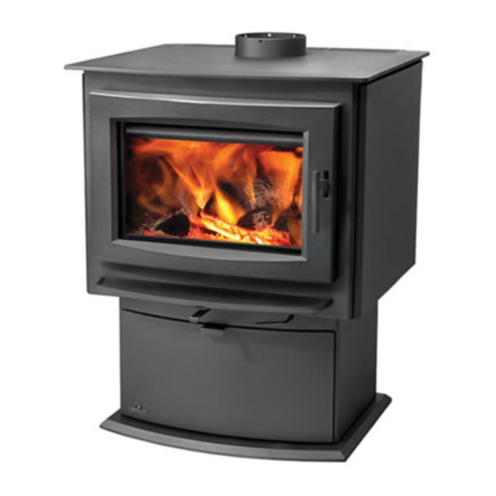
Napoleon S1 Installation And Operating Instructions Manual
Pedestal models
Hide thumbs
Also See for S1:
- Installation and operating instructions manual (40 pages) ,
- Assembly replacement instructions (2 pages) ,
- Installation instructions (1 page)
Table of Contents
Advertisement
Available languages
Available languages
CONSUMER: RETAIN THIS MANUAL FOR FUTURE REFERENCE.
NEVER LEAVE CHILDREN OR OTHER AT RISK INDIVIDUALS ALONE WITH THE APPLIANCE.
This wood appliance needs periodic inspection and repair for proper operation. It is against United States federal
regulation to operate this wood appliance in a manner inconsistent with operating instructions in this manual.
MODEL S1, S4 & S9 MEET THE 2015 U.S ENVIRONMENTAL PROTECTION AGENCY (E.P.A.) CRIB WOOD EMISSION LIMITS FOR WOOD STOVES SOLD AFTER
MAY 15, 2015, 40 C.F. R. PART 60. THESE STOVES HAVE BEEN TESTED AND LISTED BY INTERTEK TESTING SERVICES TO STANDARDS: CSA B366.2,
S1, S4 & S9
PEDESTAL MODELS
FOR INDOOR USE ONLY!
SAFETY INFORMATION
WARNING
!
If the information in these instructions is not followed exactly, a
fi re or explosion may result causing property damage, personal
injury or death. Improper installation, adjustment, alteration,
service or maintenance can cause injury or property damage,
bodily injury or even death. Please read entire manual before
you install and use your appliance.
This appliance has not been tested with an unvented gas log
set. To reduce risk of fi re or injury, do not install an unvented
gas log set into the appliance.
- This appliance can be very hot when burning.
- Combustible materials such as fi rewood, wet clothing, etc. placed too close
can catch fi re.
- Children and pets must be kept from touching the appliance when it is hot.
- The chimney must be sound and free of cracks. Before installing this unit,
contact the local building or fi re authority and follow their guidelines.
- Operate only with the door tightly closed.
- Burn wood behind the log retainer directly on the fi rebricks.
- Do not use an elevated grate or otherwise raise the fi re.
- At least 14 square inches (90.3 square centimeters) of outside air must be
admitted to the room or directly to the unit through a 4" (101.6mm) diameter
pipe.
- This appliance is designed to burn natural wood only. Higher effi ciencies and
lower emissions generally result when burning air dried seasoned hardwoods,
as compared to softwoods or to green or freshly cut hardwoods.
- Do not start a fi re with chemicals or fl uids such as gasoline, engine oil, etc.
- Do not burn trash or garbage, lawn clippings / waste, rubber, waste petroleum
products, paints or paint thinners / solvents, plastic, materials containing
asbestos, construction debris, railroad ties or treated wood, manure or animal
remains, salt water driftwood or salted materials, unseasoned wood, coal,
charcoal, coloured paper, cardboard, plywood or particleboard.
- Do not let the appliance become hot enough for any part to glow red.
- KEEP THE STOVE TOP TEMPERATURE BELOW 700°F (371°C). Attempts to
achieve heat output rates that exceed design specifi cations can result in steel
distortion and damage.
Phone 1 (866) 820-8686 • www.napoleonfi replaces.com • hearth@napoleonproducts.com
$10.00
INSTALLER: LEAVE THIS MANUAL WITH THE APPLIANCE.
OPERATING INSTRUCTIONS
ULC S627, UL 1482.
Wolf Steel Ltd., 24 Napoleon Rd., Barrie, ON, L4M 0G8 Canada /
103 Miller Drive, Crittenden, Kentucky, USA, 41030
INSTALLATION AND
!
AVERTISSEMENT
!
WARNING
HOT GLASS WILL CAUSE
BURNS.
DO NOT TOUCH GLASS UNTIL
COOLED.
NEVER ALLOW CHILDREN TO
TOUCH GLASS.
9001 - 2015
LA VITRE CHAUDE CAUSERA
DES BRÛLURES.
NE PAS TOUCHER LA VITRE
AVANT QU'ELLE AIT REFROIDI.
NE JAMAIS LAISSER LES
ENFANTS TOUCHER LA VITRE.
1.27E
W415-1476 / C / 10.03.17
EN
FR
PG
43
Advertisement
Chapters
Table of Contents

Related Manuals for Napoleon S1


Summary of Contents for Napoleon S1
-
Page 1: Safety Information
OPERATING INSTRUCTIONS MODEL S1, S4 & S9 MEET THE 2015 U.S ENVIRONMENTAL PROTECTION AGENCY (E.P.A.) CRIB WOOD EMISSION LIMITS FOR WOOD STOVES SOLD AFTER MAY 15, 2015, 40 C.F. R. PART 60. THESE STOVES HAVE BEEN TESTED AND LISTED BY INTERTEK TESTING SERVICES TO STANDARDS: CSA B366.2, ULC S627, UL 1482. -
Page 2: Table Of Contents
GLASS REPLACEMENT SECONDARY AIR MANIFOLD REPLACEMENT CARE OF GLASS CARE OF PLATED PARTS WOOD REPLACEMENTS S1 OVERVIEW S4 OVERVIEW S9 OVERVIEW S1, S4 & S9 DOOR ASSEMBLY 10.0 S1, S4 & S9 ACCESSORIES 11.0 TROUBLESHOOTING 12.0 WARRANTY 13.0 SERVICE HISTORY NOTE: Changes, other than editorial, are denoted by a vertical line in the margin. -
Page 3: Installation Overview
1.0 INSTALLATION OVERVIEW Rating plate, see “RATING PLATE INFORMATION ” section. Door, see “DOOR REMOVAL AND INSTALLATION” section. Blower, see “OPTIONAL BLOWER KIT INSTALLATION” section. Draft, see “AIR CONTROL” section. Handle, see “DOOR AND HANDLE INSTALLATION AND SERVICE” section. Ash drawer, see “ASH DRAWER ADJUSTMENT”... -
Page 4: Introduction
2.0 INTRODUCTION WARNING • THIS APPLIANCE IS HOT WHEN OPERATED AND CAN CAUSE SEVERE BURNS IF CONTACTED. • ANY CHANGES OR ALTERATIONS TO THIS APPLIANCE OR ITS CONTROLS CAN BE DANGEROUS AND IS PROHIBITED. • Do not operate appliance before reading and understanding operating instructions. Failure to operate appliance according to operating instructions could cause fi re or injury. -
Page 5: Dimensions
7 1/4" DIMENSIONS 184mm Ø 6 " 152mm 32" 812mm 12 3/4" 324mm 25 1/2" 648mm 22” S1 ILLUSTRATED 559mm 7 1/4" Ø 6 " 184mm 152mm 32" 812mm 12 3/4" 324mm 26 1/2" 25 1/2" S4 ILLUSTRATED 673mm 648mm Ø... -
Page 6: Specifications
SPECIFICATIONS SPECIFICATIONS FIREBOX CHAMBER 13 1/2”x18”x12” 18”x18”x12” 22 1/2”x18”x12” (34.3cmx45.7cmx30.5cm) (45.7cmx45.7cmx30.5cm) (57.2cmx45.7cmx30.5cm) CAPACITY 1.7 ft (0.05m 2.25 ft (0.06m 3.0 ft (0.09m APPROX. AREA HEATED** 600-1500 ft 1000-2000 ft 1000-3500 ft (56-139m (93-186m (93-325m MAXIMUM HEAT OUTPUT*** 55,000 BTU/ Hr 70,000 BTU/ Hr 85,000 BTU/ Hr HEAT OUTPUT*... -
Page 7: General Information
GENERAL INFORMATION WARNING DO NOT OPERATE THIS APPLIANCE WITHOUT THE PEDESTAL INSTALLED. Your appliance has been specifically designed to meet the 2015 U.S.A. EPA particulate emission standards and has been extensively tested in Canadian and American laboratories. This system is the most efficient, simple and trouble free we know and works as follows: The chimney vent system used on your wood burning appliance should be designed with the least amount of restriction possible to enable the exhaust products to easily flow through it. -
Page 8: Rating Plate Information
CONFORME ET UNE PLAQUE DE INSTALL WITH A POSITIVE RECOUVREMENT. FLUE CONNECTOR AND FACEPLATE. WOLF STEEL LTD. EPA1400 24 NAPOLEON ROAD, BARRIE, ON, L4M 0G8 CANADA W385-2031 / B MAXIMUM SIZE: 6" x 11.250" S4 SERIES RATING PLATE ILLUSTRATED SILVER ON BLACK BACKGROUND SPECIFICATIONS: WATERPROOF, NONWATER SOLUBLE ADHESIVE CAPABLE OF WITHSTANDING A MAXIMUM TEMPERATURE OF 175°F (79°C). -
Page 9: Pre-Installation Preparation
3.0 PRE-INSTALLATION PREPARATION APPLIANCE PLACEMENT Have an authorized dealer install the appliance. If you install the appliance yourself, have your dealer review your installation plans and/or installation. Draw out a detailed plan of the installation including dimensions and verify the dimensions with the requirements listed in this manual. -
Page 10: Alcove Installation
ALCOVE INSTALLATION 1100 series only may be installed, using a listed double wall connector, S1 and S4 models only may be installed, using a listed double wall such as Security DL6 in Canada, the Simpson Duravent Plus DVL in 9”... -
Page 11: Outside Air - Mobile Home
USE A CHIMNEY CERTIFIED FOR WOOD BURNING UL 103 S629, TYPE HT (2100°F). MODEL S1 IS APPROVED FOR INSTALLATION IN MOBILE HOMES IN THE UNITED STATES & CANADA. MODEL S4 IS APPROVED FOR INSTALLATION IN MOBILE HOMES IN THE UNITED STATES ONLY. -
Page 12: Installation
4.0 INSTALLATION WARNING WEAR PROTECTIVE GLOVES, SAFETY GLASSES, AND BOOTS/SHOES. CAREFULLY FOLLOW THE INSTRUCTIONS FOR ASSEMBLY OF THE PIPE AND OTHER PARTS NEEDED TO INSTALL THE APPLIANCE. FAILURE TO DO SO MAY RESULT IN A FIRE, ESPECIALLY IF COMBUSTIBLES ARE TOO CLOSE TO THE APPLIANCE OR CHIMNEY AND AIR SPACES ARE BLOCKED, PREVENTING THE FREE MOVEMENT OF COOLING AIR. -
Page 13: Chimney
CHIMNEY WARNING NEVER INSTALL A SINGLE WALL SLIP SECTION OR SMOKE PIPE IN A CHASE STRUCTURE. THE HIGHER TEMPERATURE OF THIS SINGLE WALL PIPE MAY RADIATE SUFFICIENT HEAT TO COMBUSTIBLE CHASE MATERIALS TO CAUSE FIRE. DO NOT CONNECT THIS APPLIANCE TO A CHIMNEY SYSTEM SERVING ANOTHER APPLIANCE. TO AVOID DANGER OF FIRE, ALL INSTRUCTIONS MUST BE STRICTLY FOLLOWED, INCLUDING THE PROVISIONS OF AIR SPACE CLEARANCE BETWEEN CHIMNEY SYSTEM AND ENCLOSURE. -
Page 14: Chimney Connection
4.1.1 CHIMNEY CONNECTION Your chimney connector and chimney must have the same diameter as the appliance’s exhaust flue outlet. The appliance pipe must be made of aluminized or cold roll steel with a minimum 24 gauge (0.6mm) thickness. It is strictly forbidden to use galvanized steel. A 6”... -
Page 15: Sections
4.1.2 SECTIONS Add chimney sections, according to the manufacturers installation instructions. The chimney must extend at least, 3 feet (1m) above its point of contact with the roof and at least 24 inches (61cm) higher than any wall, roof, building or obstacle within 10 feet (3m) horizontally. LESS THAN 10 FEET (3m) -
Page 16: Typical Through The Ceiling
4.1.3 TYPICAL THROUGH THE CEILING Move the stove into position with the fl ue centered, midpoint between two joists to prevent having to cut them. Use a plumb bob to line up the center. Cut and frame an opening in the ceiling to provide a 2” (50.8mm) clearance between the outside of the chimney and any combustible material. -
Page 17: Typical Through The Wall
4.1.4 TYPICAL THROUGH THE WALL If possible, design the installation so that the connector does not pass through a combustible wall. If during your installation you must pass through a combustible wall, check with your building inspector before you begin. Also check with the chimney connector manufacturer for any specifi c requirements. Consult with your dealer regarding special connection components available for use for wall pass-throughs. -
Page 18: Finishing
5.0 FINISHING DOOR REMOVAL / INSTALLATION Ensure to have a firm grip of the door at all times. NOTE: We recommend having two people perform this installation. Remove the bottom door hinge retainer by removing the screw, as shown below, then loosen the top door hinge retainer. -
Page 19: Handle And Door Service And Installation
POIGNÉE ÉPINGLES HANDLE AND DOOR SERVICE AND INSTALLATION ÉPINGLES WARNING RESSORT BURNING YOUR APPLIANCE WITH THE DOORS OPEN OR AJAR CREATES A FIRE HAZARD THAT MAY RESULT IN A HOUSE AND OR CHIMNEY FIRE. DO NOT STRIKE OR SLAM DOOR. RESSORT NEVER REMOVE THE DOOR WHEN THE APPLIANCE IS HOT. -
Page 20: Bricks And Baffle Installation
BRICKS AND BAFFLE INSTALLATION WARNING OPERATION OF THE APPLIANCE WITHOUT THE BAFFLES CAN RESULT IN EXCESSIVE TEMPERATURES THAT COULD DAMAGE THE APPLIANCE, CHIMNEY AND THE SURROUNDING ENCLOSURE. With appliance and chimney installation completed, move the bricks into place for your appliance as illustrated. -
Page 21: Ash Drawer Adjustment
PART # PART # FIREBRICK FIREBRICK DIMENSIONS DIMENSIONS 4 1/2” x 9” W090-0015 2 1/4” x 9” W090-0018 (114mm x 229mm) (57mm x 229mm) 3” x 9” (Molded) W090-0002 1 3/4” x 4 3/4” W090-0216 (6mm x 229mm) (64mm x 121mm) 4 1/2”... -
Page 22: Optional Kit Installations
6.0 OPTIONAL KIT INSTALLATIONS BLOWER KIT INSTALLATION WARNING WARNING WARNING RISK OF FIRE AND ELECTRICAL SHOCK. RISK OF FIRE AND ELECTRICAL SHOCK. RISK OF FIRE AND ELECTRICAL SHOCK. TURN OFF THE GAS AND ELECTRICAL POWER BEFORE SERVICING THIS APPLIANCE. TURN OFF THE GAS AND ELECTRICAL POWER BEFORE SERVICING THIS APPLIANCE. TURN OFF THE GAS AND ELECTRICAL POWER BEFORE SERVICING THIS APPLIANCE. -
Page 23: Door Trim Kit
DOOR TRIM KIT Open the door of the appliance. Remove the right side screw, holding the top door hinge retainer in place. Place one shim against the door, on the left side. Set the trim on the top of the door, align to the holes, and secure. TOP DOOR HINGE RETAINER DOOR TRIM... - Page 24 Your appliance is Hi-Tech, designed with the most advanced technology. This appliance is extremely airtight. It has an exclusive direct outside air supply (optional kit), a feature designed to prevent spillage, and to help keep your house free of carbon monoxide, in case of a down drafting chimney or an internal negative pressure.
-
Page 25: Optimum Burn Method
OPTIMUM BURN METHOD For optimal emissions performance and efficiency follow these simple guidelines when using your appliance: Maintain a 2" (51mm) deep, hot, glowing red coal bed. Burn dry seasoned wood with less than 20% moisture content and burn so that the glass door remains clean. -
Page 26: Fuel
FUEL WARNING DO NOT STORE FUEL WITHIN THE CLEARANCE TO COMBUSTIBLES, OR IN THE SPACE REQUIRED FOR RE-FUELING AND ASH REMOVAL. BURNING WET, UNSEASONED WOOD CAN CAUSE EXCESSIVE CREOSOTE ACCUMULATION. WHEN IGNITED IT CAN CAUSE A CHIMNEY FIRE THAT MAY RESULT IN A SERIOUS HOUSE FIRE. Maximum heat for minimum fuel (optimum burn) occurs when the appliance top temperature is between 500°F (260°C) and 600°F (315°C). -
Page 27: Smoking
SMOKING A properly installed appliance should not smoke. If yours does, check the following: • Has the chimney had time to get hot? • Is the smoke passage blocked anywhere in the appliance, chimney connector or chimney? • Is the room too airtight and the air intake not connected to the outside? Try with a window partly open. •... -
Page 28: Creosote Formation And Removal
CREOSOTE FORMATION AND REMOVAL When wood is burned slowly, it produces tar and other organic vapors, which combine with expelled moisture to form creosote. The creosote vapors condense in the relatively cooler chimney fl ue of a slow-burning fi re. As a result, creosote residue accumulates on the fl... -
Page 29: Glass Replacement
GLASS REPLACEMENT WARNING DO NOT USE SUBSTITUTE MATERIALS. GLASS MAY BE HOT, DO NOT TOUCH GLASS UNTIL COOLED. CARE MUST BE TAKEN WHEN REMOVING AND DISPOSING OF ANY BROKEN DOOR GLASS OR DAMAGED COMPONENTS. BE SURE TO VACUUM UP ANY BROKEN GLASS FROM INSIDE THE APPLIANCE BEFORE OPERATION. -
Page 30: Secondary Air Manifold Replacement
Check the airwash gasket located inside the appliance above the door, replace if deteriorated. Contact your Napoleon dealer for specific type and size of the materials required. NOTE: Do not operate appliance if the manifold, airwash shield or fibre baffle is deteriorated or missing. -
Page 31: Care Of Glass
CARE OF GLASS If the glass is not kept clean permanent discolouration and / or WARNING blemishes may result. Normally a hot fi re will clean the glass. The most common reasons for dirty glass include: not using HOT GLASS WILL suffi... -
Page 32: Wood
WOOD WARNING THIS APPLIANCE IS DESIGNED TO BURN NATURAL WOOD ONLY. DO NOT BURN TREATED WOOD, COAL, CHARCOAL, COLOURED PAPER, CARDBOARD, SOLVENTS OR GARBAGE. THIS APPLIANCE HAS NOT BEEN TESTED WITH AN UNVENTED GAS LOG SET. TO REDUCE RISK OF FIRE OR INJURY, DO NOT INSTALL AN UNVENTED GAS LOG SET INTO THE APPLIANCE. -
Page 33: Replacements
9.0 REPLACEMENTS WARNING FAILURE TO POSITION THE PARTS IN ACCORDANCE WITH THIS MANUAL OR FAILURE TO USE ONLY PARTS SPECIFICALLY APPROVED WITH THIS APPLIANCE MAY RESULT IN PROPERTY DAMAGE OR PERSONAL INJURY. Contact your dealer for questions concerning prices and policies on replacement parts. Normally, all parts ** THIS IS A FAST ACTING THERMOCOUPLE. -
Page 34: S1 Overview
W415-1476 / C / 10.03.17... -
Page 35: S4 Overview
W415-1476 / C / 10.03.17... -
Page 36: S9 Overview
W415-1476 / C / 10.03.17... -
Page 37: S1, S4 & S9 Door Assembly
W415-1476 / C / 10.03.17... -
Page 38: S1, S4 & S9 Accessories
W415-1476 / C / 10.03.17... -
Page 39: Troubleshooting
11.0 TROUBLESHOOTING WARNING TURN OFF THE ELECTRICAL POWER BEFORE SERVICING THE APPLIANCE. APPLIANCE MAY BE HOT, DO NOT SERVICE UNTIL APPLIANCE HAS COOLED. DO NOT USE ABRASIVE CLEANERS. WHEN CHECKING CONNECTIONS, INSTALLING JUMPER WIRES (FOR TEST PURPOSES ONLY) OR REPLACING COMPONENTS, UNPLUG HEATER FROM THE RECEPTACLE TO PREVENT ELECTRICAL SHOCK OR DAMAGE TO THE COMPONENT. -
Page 40: Warranty
All parts replaced under the President’s Limited Lifetime Warranty Policy are subject to a single claim. During the fi rst 10 years NAPOLEON will replace or repair the defective parts covered by the lifetime warranty at our discretion free of charge. From 10 years to life, NAPOLEON will provide replacement parts at 50% of the current retail price. -
Page 41: Service History
13.0 SERVICE HISTORY 43.1 W415-1476 / C / 10.03.17... - Page 42 NAPOLEON CELEBRATING OVER 40 YEARS OF HOME COMFORT PRODUCTS 7200, Route Transcanadienne, Montréal, Québec H4T 1A3 24 Napoleon Road, Barrie, Ontario, Canada L4M 0G8 214 Bayview Drive, Barrie, Ontario, Canada L4N 4Y8 103 Miller Drive, Crittenden, Kentucky, USA 41030 Phone: 1-866-820-8686...
- Page 43 D’OPÉRATION LE MODÈLE S1, S4 & S9 RESPECTE L’AGENCE DE PROTECTION DE L’ENVIRONNEMENT AMÉRICAINE (E.P.A) 2015 ES LIMITES D’ÉMISSIONS DE BOIS DE VALEUR STANDARD POUR LES POÊLES À BOIS VENDUS APRÈS LE 15 MAI 2015, 40 C.F. R. SECTION CES APPAREILS ONT ÉTÉ TESTÉS ET HOMOLOGUÉS PAR INTERTEK TESTING SERVICES SELON LES NORMES: CSA B366.2, ULC S627, UL 1482.
- Page 44 COLLECTEUR D’AIR SECONDAIRE SOINS DE LA VITRE SOINS DES PIÈCES PLAQUÉES BOIS RECHANGES VUE D’ENSEMBLE DU S1 S4 OVERVIEW S1, S4 & S9 DOOR ASSEMBLY 10.0 S1, S4 & S9 ACCESSORIES 11.0 GUIDE DE DÉPANNAGE 12.0 GARANTIE REMARQUE: Les changements autres que de nature éditoriale sont dénotés par une ligne verticale dans la marge.
-
Page 45: Vue D'ensemble De L'installation
1.0 VUE D’ENSEMBLE DE L’INSTALLATION Plaque d’homologation, voir la section « INFORMATION SUR LA PLAQUE D'HOMOLOGATION ». Porte, voir les sections « ENLÈVEMENT ET INSTALLATION DE LA PORTE ». Soufflerie, voir la section «INSTALLATION DE LA SOUFFLERIE OPTIONNEL». Retour d’air, voir la section «CONTRÔLE D’AIR». -
Page 46: Introduction
2.0 INTRODUCTION WARNING • CET APPAREIL EST CHAUD LORSQU’IL FONCTIONNE ET PEUT CAUSER DE GRAVES BRÛLURES EN CAS DE CONTACT. • TOUTE MODIFICATION APPORTÉE À CET APPAREIL OU AUX CONTRÔLES PEUT ÊTRE DANGEREUX ET EST INTERDIT. • Ne faites pas fonctionner l’appareil avant d’avoir lu et compris les instructions d’opération. Omettre d’utiliser l’appareil selon les instructions d’opération pourrait causer un incendie ou des blessures. -
Page 47: Dimensions
DIMENSIONS 7 1/4" 184mm Ø 6 " 152mm 34" 864mm 12 3/4" 324mm 25 1/2" 648mm S1 ILLUSTRÉ 22” 559mm 7 1/4" Ø 6 " 184mm 152mm 34" 864mm 12 3/4" 324mm 26 1/2" 25 1/2" 673mm S4 ILLUSTRÉ 648mm Ø... -
Page 48: Spécifications
SPÉCIFICATIONS SPÉCIFICATIONS CHAMBRE DU FOYER 13 1/2”x18”x12” 18”x18”x12” 22 1/2”x18”x12” (34.3cmx45.7cmx30.5cm) (45.7cmx45.7cmx30.5cm) (57.2cmx45.7cmx30.5cm) CAPACITÉ 1.7 ft (0.05m 2.25 ft (0.06m 3.0 ft (0.09m SURFACE CHAUFFÉE 600-1500 ft 1000-2000 ft 1000-3500 ft APPROX.** (56-139m (93-186m (93-325m DÉBIT DE CHALEUR 55,000 BTU/ Hr 70,000 BTU/ Hr 85,000 BTU/ Hr MAXIMALE***... -
Page 49: Information Générale
INFORMATION GÉNÉRALE AVERTISSEMENT NE PAS UTILISER CET APPAREIL SANS QUE LE PIÉDESTAL SOIT INSTALLÉ. Votre appareil a été conçu afin de répondre spécifiquement aux exigences des normes d’émissions de particules de l’E.P.A. américaine de 2015 et a subi un nombre considérable de tests dans des laboratoires canadiens et AVERTISSEMENT américains. -
Page 50: Information Sur La Plaque D'homologation
INSTALL WITH A POSITIVE RECOUVREMENT. FLUE CONNECTOR AND FACEPLATE. WOLF STEEL LTD. EPA1400 24 NAPOLEON ROAD, BARRIE, ON, L4M 0G8 CANADA W385-2031 / B MAXIMUM SIZE: 6" x 11.250" PLAQUE D’HOMOLOGATION DU POÊLE ILLUSTRÉE (1400). SILVER ON BLACK BACKGROUND SPECIFICATIONS: WATERPROOF, NONWATER SOLUBLE ADHESIVE CAPABLE OF WITHSTANDING A MAXIMUM TEMPERATURE OF 175°F (79°C). -
Page 51: Planification De L'installation
3.0 PLANIFICATION DE L’INSTALLATION INSTALLATION DE L’APPAREIL Faites installer votre poêle par un détaillant autorisé. Si vous l’installez vous-même, faites vérifi er vos plans d’installation et/ou l’installation par votre détaillant. Élaborez un plan détaillé de l’installation en y incluant les dimensions puis vérifi ez les dimensions avec les exigences énoncées dans ce manuel. -
Page 52: Installation Dans Une Alcôve
INSTALLATION DANS UNE ALCÔVE Seuls les appareils de la série 1100 peuvent être installés dans Modèles S1 et S4 seulement peuvent être installés dans une alcôve en une alcôve en utilisant un conduit de raccordement à double paroi utilisant un conduit de raccordement à double paroi certifié. Ce conduit 9”... -
Page 53: Prise D'air Extérieur - Maison Mobile
INSTALLEZ CONFORMÉMENT À LA NORME 24 CFR. PART 3290 (HUD). UTILISEZ UNE CHIMINÉE DE TYPE UL 103ht S629 (2100°F) CERTIFIÉE POUR LA COMBUSTION DE BOIS. MODÈLE S1 EST HOMOLOGUÉS POUR INSTALLATION DANS LES MAISONS MOBILES AUX ÉTATS-UNIS ET CANADA. MODÈLE S4 EST HOMOLOGUÉS POUR INSTALLATION DANS LES MAISONS MOBILES AUX ÉTATS-UNIS UNIQUEMENT. -
Page 54: Installation
4.0 INSTALLATION AVERTISSEMENT PORTEZ DES GANTS, DES LUNETTES, ET DES BOTTES/CHAUSSURES DE PROTECTION. SUIVEZ ATTENTIVEMENT LES INSTRUCTIONS POUR L'ASSEMBLAGE DE LA CHEMINÉE ET DES AUTRES COMPOSANTS NÉCESSAIRES À L'INSTALLATION DE L’APPAREIL. TOUTE OMISSION POURRAIT CAUSER UN INCENDIE, PARTICULIÈREMENT SI DES MATÉRIAUX COMBUSTIBLES SONT TROP PRÈS DE L’APPAREIL OU DE LA CHEMINÉE ET QUE DES OUVERTURES D'AIR SONT BLOQUÉES, EMPÊCHANT LA LIBRE CIRCULATION DE L'AIR DE REFROIDISSEMENT. -
Page 55: Cheminée
CHEMINÉE AVERTISSEMENT NE JAMAIS INSTALLER UN CONDUIT DE RACCORDEMENT À PAROI SIMPLE DANS UNE ENCEINTE. LES TEMPÉRATURES PLUS ÉLEVÉES DE CE CONDUIT PEUVENT IRRADIER SUFFISAMMENT DE CHALEUR AUX MATÉRIAUX COMBUSTIBLES POUR CAUSER UN INCENDIE. NE RACCORDEZ PAS CET APPAREIL AU CONDUIT D’UNE CHEMINÉE DESSERVANT UN AUTRE APPAREIL. POUR ÉVITER LE RISQUE D’INCENDIE, VOUS DEVEZ SUIVRE TOUTES LES INSTRUCTIONS À... -
Page 56: Installation De La Cheminée
4.1.1 INSTALLATION DE LA CHEMINÉE Votre conduit de raccordement et votre cheminée doivent avoir le même diamètre que le tuyau d’échappement de l’appareil. Le tuyau de l’appareil doit être en acier aluminié ou en acier laminé à froid d’une épaisseur minimale de calibre 24 (0.6mm). Il est strictement interdit d’utiliser de l’acier galvanisé. Un conduit de raccordement à... -
Page 57: Ajout De Sections
4.1.2 AJOUT DE SECTIONS Ajoutez des sections de cheminée, selon les instructions d’installation des manufacturiers. La cheminée doit dépasser le toit d’au moins 3’ (0,9m) de son point de contact avec la toiture, et 2’ (0,6m) de tout mur, toit ou édifi ce se trouvant à... -
Page 58: Typique À Travers Le Plafond
4.1.3 TYPIQUE À TRAVERS LE PLAFOND Mettez l’appareil en place. Repérez le centre de la buse de façon à ne pas avoir à couper les solives. Utilisez un fi l à plomb pour aligner le centre de la buse. Découpez et charpentez une ouverture dans le plafond de façon à fournir un dégagement de 2”... -
Page 59: Installation Typique À Travers Un Mur
4.1.4 INSTALLATION TYPIQUE À TRAVERS UN MUR Si possible, l’installation des conduits de raccordement ne doit pas passer à travers un mur combustible. S’il faut absolument passer à travers un mur combustible, consultez votre inspecteur en bâtiment avant de procéder. Consultez aussi le fabricant des conduits de raccordement pour connaître toutes les exigences particulières. -
Page 60: Installation Typique Dans Une Cheminée De Maçonnerie Existante
4.1.5 INSTALLATION TYPIQUE DANS UNE CHEMINÉE DE MAÇONNERIE EXISTANTE Vous pouvez aussi installer votre appareil en utilisant votre cheminée de maçonnerie existante. Pour ce faire, suivez les directives suivantes. Nous vous conseillons d’installer un coupe-feu préfabriqué ou d’en construire un. Si vous utilisez une cheminée en maçonnerie, vous devez vous assurer qu’elle réponde aux CHEVRON... -
Page 61: Finitions
5.0 FINITIONS ENLÈVEMENT ET INSTALLATION DE LA PORTE Assurez-vous de bien tenir la porte en tout temps. NOTE: Nous recommandons que deux personnes effectuent cette installation. Retirez le support de charnière inférieure de la porte en enlevant la vis, comme illustré ci-dessous, puis desserrez le support de charnière supérieure de la porte. -
Page 62: Installation De La Poignée De Porte Et De La Porte
INSTALLATION DE LA POIGNÉE DE PORTE ET DE LA PORTE AVERTISSEMENT FAIRE FONCTIONNER CET APPAREIL AVEC LES PORTES OUERTES OU ENTROUVERTES CRÉE UN RISQUE D’INCENDIE DE CHEMINÉE OU DOMICILE. AVERTISSEMENT NE FRAPPEZ PAS ET NE CLAQUEZ PAS LA PORTE. N’ENLEVEZ JAMAIS LA PORTE LORSQUE L’APPAREIL EST CHAUD. Retirez les deux vis qui fi xent le bloc de loquet à... -
Page 63: Installation Des Briques Et Des Déflecteurs En Fibre
INSTALLATION DES BRIQUES ET DES DÉFLECTEURS EN FIBRE AVERTISSEMENT L’UTILISATION DE L’APPAREIL SANS LES DÉFLECTEURS PEUT CAUSER DES TEMPÉRATURES EXCESSIVES QUI POURRAIENT ENDOMMAGER L’APPAREIL, LA CHEMINÉE ET L’ENCEINTE. Une fois l’installation de l’appareil et du tuyau de raccordement complétée, mettez les briques en AVERTISSEMENT place en procédant tel qu’illustré... -
Page 64: Ajustement Du Tiroir À Cendres
NOTE: BRICKS E & F ARE NOTCHED AT REAR. (Fibre Baffles) W018-0130 X2 PART # PART # DIMENSIONS DE DIMENSIONS DE BRIQUES BRIQUES 4 1/2” x 9” W090-0015 2 1/4” x 9” W090-0018 (114mm x 229mm) (57mm x 229mm) 3” x 9” (Moulée) W090-0002 1 3/4”... -
Page 65: Installations Des Ensembles Optionnelle
6.0 INSTALLATIONS DES ENSEMBLES OPTIONNELLE INSTALLATION DE L’ ENSEMBLE DU SOUFFLERIE AVERTISSEMENT RISQUE D’INCENDIE ET DE CHOC ÉLECTRIQUE. COUPEZ L’ALIMENTATION EN GAZ ET L’ALIMENTATION ÉLECTRIQUE AVANT DE PROCÉDER À L’ENTRETIEN DE L’APPAREIL. N’UTILISEZ QUE LES ACCESSOIRES OPTIONNELS ET LES PIÈCES DE RECHANGE APPROUVÉS PAR WOLF STEEL POUR CET APPAREIL. -
Page 66: Fonctionnement
GARNITURE DU PORTE Ouvrir la porte de l’appareil. Enlèver le vis aux côté gauche, tenir le gond support supérieure du porte en place. Placer une rondelle contre la porte, aux côté gauche. Placer la garniture en haut du porte, aligner les trous, puis fixer en place. GOND SUPPORT SUPÉRIEURE DU PORTE... - Page 67 Votre appareil Napoléon certifié aux normes EPA est un appareil de haute technologie conçu selon les principes technologiques les plus avancés. Cet appareil est extrêmement hermétique et est équipé d’une alimentation directe d’air comburant exclusive (ensemble optionnel), un dispositif de sécurité qui empêche les écoulements afin de garder votre maison exempte de monoxyde de carbone, advenant un refoulement de cheminée ou une pression négative interne.
-
Page 68: Méthode Pour Assurer Une Combustion Optimale
MÉTHODE POUR ASSURER UNE COMBUSTION OPTIMALE Pour une performance et une efficacité optimales quant aux émissions, suivez les directives simples suivantes lors de l’utilisation de votre appareil : Maintenez une couche de braises chaudes de 2 po (51 mm). Brûlez seulement du bois sec avec moins de 20% d’humidité et veillez à ce que la porte vitrée reste propre. -
Page 69: Combustible
COMBUSTIBLE AVERTISSEMENT N’ENTREPOSEZ PAS LE BOIS À L’INTÉRIEUR DES DÉGAGEMENTS DE L’APPAREIL OU DANS L’ESPACE REQUIS POUR LE RAVITAILLEMENT OU L’ENLÈVEMENT DES CENDRES. AVERTISSEMENT BRÛLER DU BOIS VERT OU HUMIDE PEUT CAUSER DES ACCUMULATIONS EXCESSIVES DE CRÉOSOTE. LORSQU’ALLUMÉE, ELLE PEUT CAUSER UN FEU DE CHEMINÉE ET UN INCENDIE GRAVE POURRAIT S’ENSUIVRE. -
Page 70: Feu Continu
7.6.2 FEU CONTINU Chargez vos bûches de dimension plus grande de façon compacte pour empêcher les fl ammes de s’infi ltrer complètement. Après 30 minutes environ, selon la grosseur de la charge, fermez le contrôle de combustion en vérifi ant que le feu ne se soit pas éteint. NE SURCHAUFFEZ PAS L’APPAREIL! Une surchauffe peut se produire : en brûlant de grandes quantités de bois de dimension réduite, tel que des rebuts de bois de meuble, des... -
Page 71: Enlèvement Des Cendres
ENLÈVEMENT DES CENDRES AVERTISSEMENT L’ÉLIMINATION CORRECTE DES CENDRES CAUSE DES INCENDIES. NE JETEZ PAS LES CENDRES DANS DES BOÎTES EN CARTON, NE LES JETEZ PAS DANS LA COUR ET NE LES ENTREPOSEZ PAS DANS UN GARAGE. SI VOUS UTILISEZ UN ASPIRATEUR POUR NETTOYER LES CENDRES, ASSUREZ-VOUS QUE CES DERNIÈRES SOIENT ENTIÈREMENT REFROIDIES. -
Page 72: Feu De Cheminée Ou Feu Hors Contrôle
FEU DE CHEMINÉE OU FEU HORS CONTRÔLE AVERTISSEMENT UN FEU DE CHEMINÉE PEUT ENDOMMAGER VOTRE CHEMINÉE DE FAÇON PERMANENTE. POUR RÉPARER CES DOMMAGES, VOUS DEVREZ REMPLACER LES COMPOSANTS ENDOMMAGÉS. LES FEUX DE CHEMINÉE NE SONT PAS COUVERTS PAR LA GARANTIE À VIE LIMITÉE. AVERTISSEMENT Des feux hors contrôle peuvent être causés par les trois facteurs suivants : •... -
Page 73: Remplacement De La Vitre
REMPLACEMENT DE LA VITRE AVERTISSEMENT N’UTILISEZ PAS DE MATÉRIAUX DE SUBSTITUTION. LA VITRE PEUT ÊTRE CHAUDE, NE TOUCHEZ PAS LA VITRE JUSQU’À CE QU’ELLE AIT REFROIDI. USEZ DE PRUDENCE LORSQUE VOUS ENLEVEZ ET JETEZ DES DÉBRIS DE VERREOU DES COMPOSANTS ENDOMMAGÉS. ASSUREZ-VOUS D’ASPIRER TOUS LES DÉBRIS DEVERRE À L’INTÉRIEUR DE L’APPAREIL AVANT DE LE FAIRE FONCTIONNER. -
Page 74: Collecteur D'air Secondaire
COLLECTEUR D’AIR SECONDAIRE À la fin de chaque saison de chauffage, inspectez le tuyau d’air secondaire pour déceler des signes de déformation ou de détérioration. Remplacez-le si nécessaire. À ce moment, vérifiez également que le joint d’étanchéité de la porte n’est pas usé ou desserré. Remplacez-le par une corde de ½ po (12,7mm) en fibre de verre à... -
Page 75: Soins De La Vitre
SOINS DE LA VITRE Si vous ne nettoyez pas les dépôts régulièrement, la vitre risque de ATTENTION rester marquée en permanence. Normalement, un feu très chaud maintiendra la vitre propre. Les raisons les plus fréquentes pour UNE SURFACE VITREE CHAUDE lesquelles la vitre se salit sont : trop peu de combustible est utilisé... -
Page 76: Bois
BOIS AVERTISSEMENT CET APPAREIL A ÉTÉ CONÇU POUR BRÛLER DU BOIS NATUREL UNIQUEMENT. NE BRÛLEZ PAS DE BOIS TRAITÉS, DE CHARBON DE BOIS, DE CHARBON, DE PAPIERS DE COULEUR, DE CARTONS, DE SOLVANTS NI DE DÉCHETS. CET APPAREIL N’A PAS ÉTÉ TESTÉ AVEC UN ENSEMBLE DE BÛCHES À GAZ NON VENTILÉES. AFIN DE RÉDUIRE LE AVERTISSEMENT RISQUE D’INCENDIE OU DE BLESSURE, N’INSTALLEZ PAS D’ENSEMBLE DE BÛCHES À... -
Page 77: Rechanges
9.0 RECHANGES AVERTISSEMENT OMETTRE DE POSITIONNER LES PIÈCES CONFORMÉMENT À CE MANUEL OU D’UTILISER UNIQUEMENT DES PIÈCES SPÉCIFIQUEMENT APPROUVÉES POUR CET APPAREIL PEUT CAUSER DES DOMMAGES MATÉRIELS OU DES BLESSURES CORPORELLES. Contactez votre détaillant pour les questions concernant les prix et la disponibilité des pièces de ** CECI EST UN THERMOCOUPLE À... - Page 78 W415-1476 / C / 10.03.17...
-
Page 79: S4 Overview
W415-1476 / C / 10.03.17... -
Page 80: S1, S4 & S9 Door Assembly
W415-1476 / C / 10.03.17... -
Page 81: S1, S4 & S9 Accessories
W415-1476 / C / 10.03.17... -
Page 82: Guide De Dépannage
11.0 GUIDE DE DÉPANNAGE AVERTISSEMENT COUPEZ L’ALIMENTATION ÉLECTRIQUE AVANT DE PROCÉDER À L’ENTRETIEN DE L’APPAREIL. L’APPAREIL PEUT ÊTRE CHAUD. ATTENDEZ QU’IL SOIT REFROIDI AVANT D’EN FAIRE L’ENTRETIEN. N’UTILISEZ PAS DE PRODUITS D’ENTRETIEN ABRASIFS. LORSQUE VOUS VÉRIFIEZ DES CONNEXIONS, QUE VOUS INSTALLEZ DES FILS DE DÉRIVATION (POUR EFFECTUER DES TESTS UNIQUEMENT) OU QUE VOUS REMPLACEZ DES COMPOSANTS, DÉBRANCHEZ L’APPAREIL DU RÉCEPTACLE AFIN D’ÉVITER LES CHOCS ÉLECTRIQUES OU DES DOMMAGES AUX COMPOSANTS. -
Page 83: Garantie
All parts replaced under the President’s Limited Lifetime Warranty Policy are subject to a single claim. During the fi rst 10 years NAPOLEON will replace or repair the defective parts covered by the lifetime warranty at our discretion free of charge. From 10 years to life, NAPOLEON will provide replacement parts at 50% of the current retail price. - Page 84 NAPOLÉON CÉLÈBRE PLUS DE 40 ANS D’EXISTENCE CONSACRÉS À LA CONCEPTION DE PRODUITS DE CONFORT 7200, Route Transcanadienne, Montréal, Québec H4T 1A3 24 Napoleon Road, Barrie, Ontario, Canada L4M 0G8 214 Bayview Drive, Barrie, Ontario, Canada L4N 4Y8 103 Miller Drive, Crittenden, Kentucky, USA 41030 Téléphone: 1-866-820-8686...