Table of Contents
Advertisement
Advertisement
Table of Contents

Related Manuals for GE AV-300I


Summary of Contents for GE AV-300I
- Page 1 GEH-6668A Supersedes GEH-6668 GE Industrial Systems AV-300i 575V User’s Guide...
- Page 2 If further information is desired or if particular problems arise that are not covered sufficiently for the purchaser’s purpose, the matter should be referred to GE Industrial Systems, Salem, Virginia, USA.
- Page 3 Safety Symbol Legend / Légende des Signes de Sécurité ARNING Commands attention to an operating procedure, practice, condition, or statement which, if not strictly observed, could result in personal injury or death. Attire l’attention sur les modes d’utilisation et les procédés et conditions d’exploitation qui, en cas d’inobservation, pourraient entraîner des blessures corporelles ou la mort.
- Page 4 Table of Contents Safety Symbol Legend / Légende des Signes de Sécurité ..........3 Chapter 0 - Safety Precautions / Precautions de Securité .......... 13 Chapter 1 - Function and Features (Overview) ............17 Chapter 2 - Inspection Procedure, Component Identification and Standard Specification ......................
- Page 5 Figure 3.3.1: Max. angle of inclination ....................35 Figure 3.3.2: Mounting clearance .......................35 3.4. Motors and Encoders ........................36 3.4.1. Motors ........................... 36 3.4.2. Encoders ..........................37 Table 3.4.2.1: Recommended cable section and length for the connection of encoders ....37 Table 3.4.2.2: Encoders setting via S11...S23 Jumpers..............38 Table 3.4.2.3: Encoders connections ....................38 Table 3.4.2.4: Assignment of the high density XE connector for a sinusoidal or a digital encoder ..40...
- Page 6 Table 4.9.1: DC Link Buffer Time ......................66 Figure 4.9.1: Buffering the Regulator Supply by Means of Additional Intermediate Circuit Capacitors 4.10. AV-300i Power Dip Ride Through Data and Restart Setup ............68 Table 4.10.1: Drive Trip Times, 575-V Threshold .................69 4.11.
- Page 7 5.3.1 Pre Power Checks .........................101 5.3.1.1 Setting Jumpers and Switches ..................... 101 5.3.1.2 Checking the Wiring and Auxiliary Voltages................ 101 Table 5.3.1.2.1 : Terminals description ....................102 Table 5.3.1.2.2: Amps/Volts ratio ....................... 102 5.3.2 Power Up Checks ........................103 5.3.2.1 Basic Settings of the Drive for all the Regulation Modes ............. 103 5.3.2.2.
- Page 8 5.3.4.3.3.2. Manual Tuning of Flux Regulator ................... 121 5.3.4.3.3.3 Manual Tuning the Speed Regulator ................122 5.3.5 Enhanced Regulator Features ....................123 5.3.5.1. Setting the Speed Zero Logic ....................123 5.3.5.2 Anti Drift Function (Only for Field Oriented Control) ............. 123 5.3.5.3 Adaptive Speed ........................
- Page 9 6.7. Ramp ............................167 Figure 6.7.1: Ramp ..........................167 6.7.1. Acceleration, Deceleration, Quick Stop .................. 168 Figure 6.7.1.1: Accel, Decel, and Quick stop ................... 168 6.7.2. Ramp Shape and Control Commands ..................169 Figure 6.7.2.1: Ramp shape ......................170 Figure 6.7.2.2: Ramp delay ....................... 170 Figure 6.7.2.3: Ramp control ......................
- Page 10 Figure 6.13.2.2: Window comparator ....................216 6.13.3. Digital Outputs ........................218 Figure 6.13.3.1: Digital Outputs and Option card ................218 6.13.4. Digital Inputs ........................219 Figure 6.13.4.1: Digital Input and Option card .................. 220 6.13.5. Speed Reference from Encoder Input (Tach Follower Function) ...........221 Figure 6.13.5.1: Tach follower ......................
- Page 11 6.16.3 Saving Parameters. Loading Default Factory Settings, Life Time..........261 6.16.4. Failure Register ........................261 6.16.5. Signal Adaptation (Links Function) ..................262 Figure 6.16.5.1: Structure of the signal adaptation ................263 6.16.6. Pads ..........................265 Figure 6.16.6.1: Bus pads ......................... 267 6.16.7. DC Braking .........................268 Figure 6.16.7.1: DC Braking function ....................
- Page 12 Failure alarms in the keypad display ....................323 Other faults ............................326 Chapter 9 - Block Diagram ..................329 AV-300i Inverter Overview ........................ 329 Digital Inputs/Outputs & Mapping Standard and Option Cards ............330 Analog Inputs/Outputs & Mapping ....................331 Speed Reference Generation ......................
- Page 13 Chapter 0 - Safety Precautions / Precautions de Securité The terms “Inverter”, “Controller” and “Drive” are sometimes used interchangably through- out the industry. We will use the term “Drive” in this document Les mots “Inverter”, “Controller” et “Drive” sont interchangeables dans le domaine industriel.
- Page 14 Lors de l’utilisation d’instruments (par example oscilloscope) sur des systémes en marche, le chassis de l’oscilloscope doit être relié à la terre et un amplificateur différentiel devrait être utilisé en entrée. Les sondes et conducteurs doivent être choissis avec soin pour effectuer les meilleures mesures à l’aide d’un oscilloscope.
- Page 15 ! - ELECTRIC SHOCK HAZARD / A ! - CAS DE DECHARGE ELECTRIQUE: ARNING TTENTION Drives and motors must be grounded according to NEC and local codes. Replace all covers before applying power to the Drive. Failure to do so may result in death or serious injury. Adjustable frequency drives are electrical apparatus for use in industrial installations.
- Page 16 Ne pas raccorder de tension d’alimentation dépassant la fluctuation de tension permise par les normes. Dans le cas d’ une alimentation en tension excessive, des composants internes peuvent être endommagés. Ne pas faire fonctionner le drive sans prise de terre. Le chassis du moteur doit être mis à la terre à l’aide d’un connecteur de terre separé...
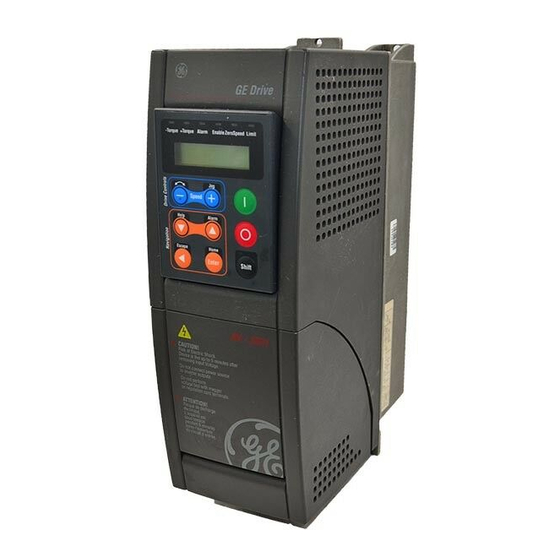
- Page 17 Chapter 1 - Function and Features (Overview) The AV-300i is a field-oriented vector Drive with excellent speed control properties and a high torque. Available control modes are: - Field oriented with speed sensor - Field oriented without speed sensor (Sensorless vect mode) - V/f control Space vector modulation keeps the noise level to a minimum.
- Page 18 Notes: GEH-6668 AV300i User’s Guide 18 • Chapter1 - Function and Features...
- Page 19 2.1. Upon Delivery Inspection Procedures 2.1.1. General A high degree of care is taken in packing the AV-300i Drives and preparing them for delivery. They should only be transported with suitable transport equipment (see weight data). Observe the instructions printed on the packaging.
- Page 20 GE Industrial Systems General Electric Company GEH-6668A 040211 1501 Roanoke Blvd. + 1 540 387 7000 SIEI Salem, VA 24153-6492 USA www.GEindustrial.com February 2004, for 575 VAC AV-300i Ver. 1.XX...