Advertisement
Quick Links
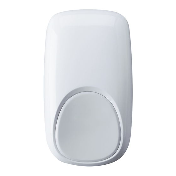
IS3050A Passive Infrared Motion Sensor with Anti-Mask - Installation Instructions
QUICK LINKS
Mounting Location Guidelines
Open the Sensor
Mounting location guidelines:
• The optimal range is obtained at a mounting height
of 7' 6" (2.3m).
• Allow a clear line-of-sight to all areas to protect.
• Avoid mounting anything within 12" (30cm) in front of the sensor.*
• Do not directly face windows.
• Avoid close proximity to moving machinery, fluorescent lights, and heating/cooling sources.
• Not for use in applications with pets.
Walk Test the Sensor
Remote LED Enable
Sensor Specifications
Accessories
Approval Listings
1. Turn the arrow to point to the Unlock symbol.
2. Press firmly on housing latch.
3. Gently separate the front and rear housing.
Advertisement

Summary of Contents for Honeywell IS3050A
- Page 1 IS3050A Passive Infrared Motion Sensor with Anti-Mask - Installation Instructions QUICK LINKS Mounting Location Guidelines Wiring Examples Mask Condition Open the Sensor Walk Test the Sensor Troubleshooting Mount the Sensor Detection Patterns Sensor Specifications Sensor Components and Settings Remote LED Enable...
- Page 2 • [A] = Wall mounting holes. • [B] = Corner mounting holes. • The rear tamper plate MUST be mounted to a stud, solid wood, or with a robust wall anchor. See wiring details and examples on page - 2 -...
- Page 3 WIRING DETAILS FOR INTERNAL EOL RESISTORS - Observe proper polarity. Notes: - Consult the Control Panel manual to determine proper EOL selection. - Connect the sensor to the panel (see - The EOL setting must only have one switch ON. wiring diagrams below).
- Page 4 Power Walk Test Normal Trouble Anti-Mask Slow Fast Blink Alarm Alarm Blink Fast Yellow Blink 1. Close the sensor and apply power to the sensor. Initialization is complete when the LED stops flashing slowly (about 20 seconds). 2. Walk through the detection area and observe the LED. Walk test mode is active for 10 minutes, then automatically exits test mode, disables the LED and enters normal operation mode.
-
Page 5: Specifications
REMOTE LED ENABLE (LED INPUT) SPECIFICATIONS The LED input terminal allows the LED to be Range: 53’ x 72’ / 16 m x 22 m remotely enabled. To use this feature, the LED Wall Mounting Height: 6’9” - 8’9” (2.1 m - 2.7 m); Optimal 7’6” (2.3 m) DIP switch (switch 2) must be OFF, allowing the Power: 9.0 - 16 VDC (UL: 9.5 - 15 VDC);... - Page 6 For the latest U.S. warranty information, please go to: www.honeywell.com/security/hsc/resources/wa or Please contact your local authorized Honeywell representative for product warranty information. 2013 Honeywell International Inc. Honeywell and DUAL TEC are registered trademarks of Honeywell International Inc. 2 Corporate Center Drive, Suite 100 All other trademarks are the properties of their respective owners.


