Cisco Catalyst 9500 Series Hardware Installation Manual
Hide thumbs
Also See for Catalyst 9500 Series:
- Manual (360 pages) ,
- Configuration manual (223 pages) ,
- Hardware installation manual (122 pages)
Table of Contents
Advertisement
Quick Links
Advertisement
Table of Contents
Troubleshooting

Related Manuals for Cisco Catalyst 9500 Series


Summary of Contents for Cisco Catalyst 9500 Series
- Page 1 Cisco Catalyst 9500 Series Switches Hardware Installation Guide First Published: 2017-06-20 Americas Headquarters Cisco Systems, Inc. 170 West Tasman Drive San Jose, CA 95134-1706 http://www.cisco.com Tel: 408 526-4000 800 553-NETS (6387) Fax: 408 527-0883...
- Page 2 Cisco and the Cisco logo are trademarks or registered trademarks of Cisco and/or its affiliates in the U.S. and other countries. To view a list of Cisco trademarks, go to this URL: www.cisco.com/go/trademarks . Third-party trademarks mentioned are the property of their respective owners. The use of the word partner does not imply a partnership relationship between Cisco and any other company.
-
Page 3: Table Of Contents
Ethernet Management Port LED Rear Panel Power Supply Slots Fan Modules Switch Installation C H A P T E R 3 Installation Tasks Safety Warnings Unpacking the Switch Establishing the System Ground Cisco Catalyst 9500 Series Switches Hardware Installation Guide... - Page 4 Installation Guidelines Installing a Fan Module Finding the Fan Module Serial Number Troubleshooting C H A P T E R 7 Getting Started Solving Problems at the System Component Level Identifying Startup Problems Cisco Catalyst 9500 Series Switches Hardware Installation Guide...
- Page 5 Configure DHCP, NTP, DNS and SNMP Settings Configuring the Switch Using the CLI Accessing the CLI Through the Console Port Connecting the RJ-45 Console Port Connecting the USB Console Port Installing the Cisco Microsoft Windows USB Device Driver Cisco Catalyst 9500 Series Switches Hardware Installation Guide...
- Page 6 Installing the Cisco Microsoft Windows XP USB Driver Installing the Cisco Microsoft Windows 2000 USB Driver Installing the Cisco Microsoft Windows Vista and Windows 7 USB Driver Uninstalling the Cisco Microsoft Windows USB Driver Uninstalling the Cisco Microsoft Windows XP and 2000 USB Driver Using the Setup.exe Program...
-
Page 7: Preface
A vertical line, called a pipe, indicates a choice within a set of keywords or arguments. [x | y] Optional alternative keywords are grouped in brackets and separated by vertical bars. Cisco Catalyst 9500 Series Switches Hardware Installation Guide... - Page 8 Use the statement number provided at the end of each warning to locate its translation in the translated safety warnings that accompanied this device. Statement 1071 SAVE THESE INSTRUCTIONS Cisco Catalyst 9500 Series Switches Hardware Installation Guide...
-
Page 9: Related Documentation
Obtaining Documentation and Submitting a Service Request For information on obtaining documentation, submitting a service request, and gathering additional information, see the monthly What's New in Cisco Product Documentation, which also lists all new and revised Cisco technical documentation, at: http://www.cisco.com/c/en/us/td/docs/general/whatsnew/whatsnew.html... - Page 10 Preface Obtaining Documentation and Submitting a Service Request Cisco Catalyst 9500 Series Switches Hardware Installation Guide...
-
Page 11: Product Overview
• 12 and 24 ports of 40G QSFP • 40 ports of 10G SFP The Catalyst 9500 Series Switches provide support for the following features: • 12/24/40 Gigabit Ethernet QSFP and SFP ports • 8-Port 10 Gigabit Ethernet(SFP) and 2-Port 40 Gigabit Ethernet(QSFP) uplinks on 40-ports switch model •... - Page 12 Ethernet (QSFP) network module on uplink ports; and two power supply slots C9500-48X 40 10-Gigabit Ethernet SFP ports and an 8-Port 10-Gigabit Ethernet (SFP) network module on uplink ports; and two power supply slots Cisco Catalyst 9500 Series Switches Hardware Installation Guide...
-
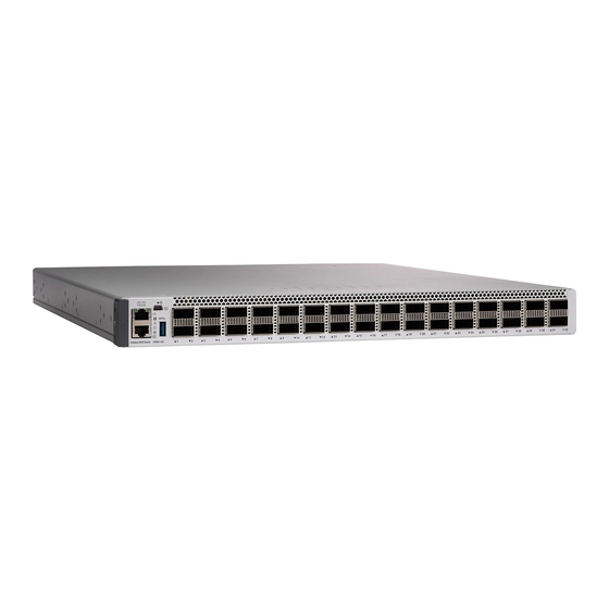
Page 13: Front Panel
Product Overview Front Panel Front Panel Figure 1: Front Panel of a 12-Port Cisco Catalyst 9500 Switch 12 40G QSFP ports USB mini Type B console port RFID Mode button Console port (RJ-45 Serial) USB 2.0 host port Blue beacon LED... -
Page 14: Cisco Catalyst 9500 Series Switches Hardware Installation Guide
Product Overview Front Panel Figure 2: Front Panel of a 24-Port Cisco Catalyst 9500 Switch 24 40G QSFP ports USB mini Type B console port RFID Mode button Console port (RJ-45 Serial) USB 2.0 host port Blue beacon LED Ethernet management RJ-45 port... -
Page 15: Cisco Catalyst 9500 Series Switches Hardware Installation Guide
Product Overview Front Panel Figure 3: Front Panel of a 40-Port Cisco Catalyst 9500 Switch 40 10G SFP ports USB mini Type B console port Network modules Mode button RFID USB 2.0 host port Console port (RJ-45 Serial) Ethernet management RJ-45 port... -
Page 16: Sfp And Qsfp Module Ports
• USB mini-Type B console port (5-pin connector). If you use the USB mini-Type B console port, the Cisco Windows USB device driver must be installed on any PC connected to the console port (for operation with Microsoft Windows). Mac OS X or Linux do not require special drivers. -
Page 17: Management Port
10G Status LED Mode Each 40G port can be configured to function as a 10G port using a Cisco QSFP to four SFP Active Optical Breakout Cables that connect a 40G QSFP port of the switch on one end to four 10G SFP ports of the switch on the other end. -
Page 18: Cisco Catalyst 9500 Series Switches Hardware Installation Guide
This module has two 40G QSFP ports. Any combination of standard QSFP modules are supported. For information about the network modules, see Installing the Network Modules section. For cable specifications, see Cables and Adapters section. Cisco Catalyst 9500 Series Switches Hardware Installation Guide... -
Page 19: Led Indicators
Figure 5: LEDs — C9500-24Q System LED Power Supply Unit(PSU) LED Blue beacon LED Fan LED 10G Status LEDs Ethernet Management port LED System LED The system LED indicates the status of the system. Cisco Catalyst 9500 Series Switches Hardware Installation Guide... -
Page 20: Power Supply Leds
One or more fans have encountered tachometer faults. One or more fans' tachometer faults have exceeded the maximum limit. Ethernet Management Port LED The following table shows the Ethernet management port LED colors and their meanings. Cisco Catalyst 9500 Series Switches Hardware Installation Guide... -
Page 21: Rear Panel
Green Link up but no activity. Amber Link up and activity. Link down. Rear Panel Figure 6: Rear Panel of a 24-Port Cisco Catalyst 9500 Switch USB 3.0 host port Grounding Pad Fan Modules Power Supply Modules Power Supply Slots The chassis has two power supply slots that accept AC-input power supplies. -
Page 22: Fan Modules
21000 rpm. The fan tray is responsible for cooling the entire chassis and interfacing with environmental monitors to trigger alarms when conditions exceed thresholds. Table 9: Fan Module supported by Catalyst 9500 Series Switches Part Number... -
Page 23: Switch Installation
Power supplies that are ordered with the switch are installed in the switch. If ordered separately, install the power supplies. Connect the power supplies. Installing a network module Install a network modules on the uplink ports. Cisco Catalyst 9500 Series Switches Hardware Installation Guide... -
Page 24: Safety Warnings
Warning servicing. Statement 1034 This product requires short-circuit (overcurrent) protection, to be provided as part of the building installation. Warning Install only in accordance with national and local wiring regulations. Statement 1045 Cisco Catalyst 9500 Series Switches Hardware Installation Guide... -
Page 25: Unpacking The Switch
• When using DC-input power supplies, you must install the system (ground before you attach the source DC power cables to the DC PEM. Power down the chassis before attaching the system ground. Cisco Catalyst 9500 Series Switches Hardware Installation Guide... -
Page 26: Required Tools And Equipment
The length of the grounding wire depends on the proximity of the switch to proper grounding facilities. • No. 1 Phillips screwdriver. • Crimping tool to crimp the grounding wire to the grounding lug. • Wire-stripping tool to remove the insulation from the grounding wire. Cisco Catalyst 9500 Series Switches Hardware Installation Guide... -
Page 27: Connecting The System Ground
Prepare the other end of the grounding wire with a ring lug, and secure it to the rack with a screw. Installing the Switch Rack-Mounting Installation in racks other than 19-inch racks requires a bracket kit not included with the switch. Cisco Catalyst 9500 Series Switches Hardware Installation Guide... - Page 28 Statement 1006 This figure shows the standard 19-inch brackets and other optional mounting brackets. You can order the optional brackets from your Cisco sales representative. Figure 8: Rack-Mounting Brackets Cisco Catalyst 9500 Series Switches Hardware Installation Guide...
- Page 29 Switch Installation Rack-Mounting 19-inch brackets 23-inch brackets Extension rails and brackets for four-point mounting, includes 19-inch brackets. Cisco Catalyst 9500 Series Switches Hardware Installation Guide...
-
Page 30: Attaching The Rack-Mount Brackets
Use four Phillips flat-head screws to attach the long side of the bracket to each side of the switch for the front- or rear-mounting positions. Figure 9: Attaching 19-inch Rack Mounting Brackets Figure 10: Attaching 23-inch Rack Mounting Brackets Cisco Catalyst 9500 Series Switches Hardware Installation Guide... - Page 31 Switch Installation Rack-Mounting Figure 11: Front, Middle and Rear Mounting positions of Rack Mounting Brackets Cisco Catalyst 9500 Series Switches Hardware Installation Guide...
-
Page 32: Mounting The Switch A Rack
Switch Installation Rack-Mounting Mounting the Switch a Rack Procedure Step 1 Use the Phillips machine screws to attach the brackets and the extension rail to the switch. Figure 12: Attaching the Extension Rail Cisco Catalyst 9500 Series Switches Hardware Installation Guide... - Page 33 Switch Installation Rack-Mounting Step 2 Use the black Phillips machine screw to attach the cable guide to the left or right bracket. Figure 13: Attaching the Cable Guide Cable guide 19-inch bracket Cisco Catalyst 9500 Series Switches Hardware Installation Guide...
-
Page 34: After Switch Installation
Front-mounting position Cable guide Number-12 or number-10 Phillips machine screws After Switch Installation • Configure the switch. For more information, see Setting up the Switch, on page • Connect to the front-panel ports. Cisco Catalyst 9500 Series Switches Hardware Installation Guide... -
Page 35: Installing A Network Module
This is supported on the following switch Note models: • C9500-40X Blank Network Module Insert this blank module when the switch has no uplink ports (this is required for (NM-C4-10G-BLANK) sufficient air flow). Cisco Catalyst 9500 Series Switches Hardware Installation Guide... - Page 36 Installing a Network Module Network Module Overview Figure 15: C9500-NM-8X Network Module 10G SFP module slots LEDs Cisco Catalyst 9500 Series Switches Hardware Installation Guide...
- Page 37 Installing a Network Module Network Module Overview Figure 16: C9500-NM-2Q Network Module 40G QSFP module slots LEDs Figure 17: Blank Network Module Cisco Catalyst 9500 Series Switches Hardware Installation Guide...
-
Page 38: Installing A Network Module In The Switch
Verify the correct orientation of your module before installing it. Incorrect installation can damage Caution the module. Do not install the network module with connected cables or installed SFP modules. Always remove Caution any cables and modules before you install the network module. Cisco Catalyst 9500 Series Switches Hardware Installation Guide... - Page 39 Position the module face up to install it in the module slot. Slide the module into the slot until the back of the module faceplate is flush with the switch faceplate. Secure the network module in place by latch. Figure 18: Installing the Network Module in the Switch Cisco Catalyst 9500 Series Switches Hardware Installation Guide...
-
Page 40: Removing A Network Module
Release latch and carefully slide the network module out of the slot. Step 4 Install a replacement network module or a blank module in the slot. Step 5 Place the module that you removed in an antistatic bag or other protective environment. Cisco Catalyst 9500 Series Switches Hardware Installation Guide... -
Page 41: Finding The Network Module Serial Number
Finding the Network Module Serial Number Finding the Network Module Serial Number If you contact Cisco Technical Assistance regarding a network module, you need to know its serial number. Figure 19: Network Module Serial Number Location Cisco Catalyst 9500 Series Switches Hardware Installation Guide... - Page 42 Installing a Network Module Finding the Network Module Serial Number Cisco Catalyst 9500 Series Switches Hardware Installation Guide...
-
Page 43: Installing A Power Supply
If you leave any power supply slots empty, you must ensure that the blank cover is installed in that slot Note to maintain the designed airflow. This table lists the power supply models. Part Number Description PWR-C4-950WAC-R 950W AC Power Supply Cisco Catalyst 9500 Series Switches Hardware Installation Guide... - Page 44 Installing a Power Supply Power Supply Overview Figure 20: Cisco Catalyst 9500 AC Input Power Supply Figure 21: Power Supply Slot Cover Release handles Cisco Catalyst 9500 Series Switches Hardware Installation Guide...
-
Page 45: Installation Guidelines
Caution devices at the source power circuit breaker, or place a piece of adhesive tape over the circuit breaker handle to prevent accidental power restoration while you are working on the circuit. Cisco Catalyst 9500 Series Switches Hardware Installation Guide... -
Page 46: Installing Power Supply
Slide the unit all the way into the power supply bay until the release latch on the front of the power supply clicks and prevents you from moving the power supply in or out of the chassis. Figure 22: Installing the Power Supply Cisco Catalyst 9500 Series Switches Hardware Installation Guide... -
Page 47: Connecting To The Power Source
• For the AC-input power supply, unplug the power cables that are attached to the power supply and the power source. Step 3 Remove the power supply from the chassis, as follows: Cisco Catalyst 9500 Series Switches Hardware Installation Guide... -
Page 48: Finding The Serial Number
Finding the Serial Number If you contact Cisco Technical Assistance, you need to know the serial number. These figures show where the serial number is located. You can also use the show version privileged EXEC command to see the serial number. -
Page 49: Chapter 6 Installing A Fan Module
The switch can operate with four operational fans and one nonfunctional fan, but the failed fan should be replaced as soon as possible to avoid a service interruption due to a second fan fault. Figure 24: Fan Module for Catalyst 9500 Switch Models Cisco Catalyst 9500 Series Switches Hardware Installation Guide... -
Page 50: Installation Guidelines
When correctly inserted, the fan module is flush with the switch rear panel. When the fan is operating, a green LED is on in the top left corner of the fan. Cisco Catalyst 9500 Series Switches Hardware Installation Guide... -
Page 51: Finding The Fan Module Serial Number
Figure 25: Installing the Fan Module Finding the Fan Module Serial Number If you contact Cisco Technical Assistance regarding a fan module, you need to know the fan module serial number. See the following illustration to find the serial number. - Page 52 Installing a Fan Module Finding the Fan Module Serial Number Cisco Catalyst 9500 Series Switches Hardware Installation Guide...
-
Page 53: Troubleshooting
The switch consists of these subsystems: Cisco Catalyst 9500 Series Switches Hardware Installation Guide... -
Page 54: Identifying Startup Problems
• If the Power Supply LED then goes on, return the first power cord for replacement. If this unit has more than one power cord, repeat Step 1 for each power supply. Cisco Catalyst 9500 Series Switches Hardware Installation Guide... -
Page 55: Troubleshooting The Fan Tray
If you are unable to solve a startup problem after using the troubleshooting suggestions in this chapter, contact a Cisco customer service representative for assistance and additional instructions. Before you call, have the following information ready to help your service provider assist you as quickly as possible:... -
Page 56: Finding The Serial Number
Finding the Serial Number If you contact Cisco Technical Assistance, you need to know the switch serial number. The figure shows where the serial number is located. You can also use the show version privileged EXEC command to see the serial number. - Page 57 Troubleshooting Finding the Serial Number RFID Caution ESD CLEI Lab Altitude MAC Number Compliance label Cisco Catalyst 9500 Series Switches Hardware Installation Guide...
- Page 58 Troubleshooting Finding the Serial Number Cisco Catalyst 9500 Series Switches Hardware Installation Guide...
-
Page 59: Appendix A Technical Specifications
Dimensions (H x W x D) 1.73 x 17.5 x 21.4 in. (4.4 x 44.5 x 56.7 cm) Rack Units (RU) 1 RU Chassis with 2 Power Supplies and Built-In 25.75lbs/11.68 kgs Fan** Cisco Catalyst 9500 Series Switches Hardware Installation Guide... - Page 60 Technical Specifications Technical Specifications This table describes the power requirements. Table 12: Power Requirements Power Requirements Input Voltage 90 to 264 VAC Cisco Catalyst 9500 Series Switches Hardware Installation Guide...
-
Page 61: Appendix B Connector And Cable Specifications
• Console Port, page 57 • Cables and Adapters, page 57 Connector Specifications 10/100/1000 Ports (Including PoE) All 10/100/1000 ports use standard RJ-45 connectors and Ethernet pinouts. Figure 28: 10/100/1000 Port Pinouts Cisco Catalyst 9500 Series Switches Hardware Installation Guide... -
Page 62: Sfp Module Connectors
Connector and Cable Specifications SFP Module Connectors SFP Module Connectors Figure 29: Duplex LC Cable Connector Figure 30: Simplex LC Cable Connector Figure 31: Copper SFP Module LC Connector Cisco Catalyst 9500 Series Switches Hardware Installation Guide... -
Page 63: Console Port
Each port must match the wave-length specifications on the other end of the cable, and the cable must not exceed the stipulated cable length. Copper 1000BASE-T SFP module transceivers use standard four twisted-pair, Category 5 cable at lengths up to 328 feet (100 meters). Cisco Catalyst 9500 Series Switches Hardware Installation Guide... -
Page 64: Cable Pinouts
Cable Pinouts Cable Pinouts Figure 34: Four Twisted-Pair Straight-Through Cable Schematic Figure 35: Four Twisted-Pair Semi-Cross Cable Schematic Figure 36: Two Twisted-Pair Straight-Through Cable Schematic Figure 37: Two Twisted-Pair Crossover Cable Schematic Cisco Catalyst 9500 Series Switches Hardware Installation Guide... -
Page 65: Console Port Adapter Pinouts
PC. You need to provide a RJ-45-to-DB-25 female DTE adapter to connect the switch console port to a terminal. Table 13: Console Port Signaling with a DB-9 Adapter Switch Console Port (DTE) RJ-45-to-DB-9 Terminal Adapter Console Device Signal DB-9 Pin Signal Cisco Catalyst 9500 Series Switches Hardware Installation Guide... - Page 66 Switch Console Port (DTE) RJ-45-to-DB-9 Terminal Adapter Console Device Signal DB-9 Pin Signal Table 14: Console Port Signaling with a DB-25 Adapter Switch Console Port (DTE) RJ-45-to-DB-25 Terminal Adapter Console Device Signal DB-25 Pin Signal Cisco Catalyst 9500 Series Switches Hardware Installation Guide...
-
Page 67: Appendix C Configuring The Switch
Set a password of up to 25 alphanumeric characters. The username password combination you set gives you privilege 15 access. The string cannot start with a number, is case sensitive, and allows spaces but ignores leading spaces. Cisco Catalyst 9500 Series Switches Hardware Installation Guide... -
Page 68: Choosing Setup Options
To ease your configuration tasks and save time, choose a site profile based on where your device may be installed and managed in your network. Based on the site profile you choose, your device is automatically configured according to Cisco best practices. You can easily modify this default configuration, from the corresponding detailed configuration screens. - Page 69 Version 2 Version 2 Version 2 Version 2 Enabled Enabled Enabled Enabled Enabled Enabled VTY Access Enabled Enabled Enabled Enabled Enabled Enabled to Switch Service Enabled Enabled Enabled Enabled Enabled Enabled Timestamp Cisco Catalyst 9500 Series Switches Hardware Installation Guide...
- Page 70 VLANs VLANs. VLANs. Cisco Catalyst 9500 Series Switches Hardware Installation Guide...
-
Page 71: Configuring Switch Wide Settings
PVRST+ is the default STP mode configured on your device. You can change it to PVST from the STP Mode drop-down list. Step 2 To change a bridge priority number from the default value 32748, change Bridge Priority to Yes and choose a priority number from the drop-down list. Cisco Catalyst 9500 Series Switches Hardware Installation Guide... -
Page 72: Configure Dhcp, Ntp, Dns And Snmp Settings
If you have stacked your switches, connect to the console port of one of the switches in the stack. You Note can initially configure the entire stack from any member switch. Cisco Catalyst 9500 Series Switches Hardware Installation Guide... -
Page 73: Connecting The Rj-45 Console Port
If you are connecting the switch USB console port to a Windows-based PC for the first time, install the USB driver. See Installing the Cisco Microsoft Windows USB Device Driver, on page USB Type A port on the switch provides file system support and is NOT a console port. See USB Note Type A Port section. -
Page 74: Installing The Cisco Microsoft Windows Usb Device Driver
Installing the Cisco Microsoft Windows XP USB Driver Procedure Step 1 Obtain the Cisco USB console driver file from the Cisco.com web site and unzip it. Note You can download the driver file from the Cisco.com site for downloading the switch software. -
Page 75: Installing The Cisco Microsoft Windows Vista And Windows 7 Usb Driver
Installing the Cisco Microsoft Windows Vista and Windows 7 USB Driver Procedure Step 1 Obtain the Cisco USB console driver file from the Cisco.com web site and unzip it. Note You can download the driver file from the Cisco.com site for downloading the switch software. -
Page 76: Using The Add Or Remove Programs Utility
Scroll to Cisco Virtual Com and click Remove. Step 3 When the Program Maintenance window appears, select the Remove radio button. Click Next. Uninstalling the Cisco Microsoft Windows Vista and Windows 7 USB Driver Before You Begin Disconnect the switch console terminal before uninstalling the driver.