Table of Contents
Advertisement
Quick Links
Download this manual
See also:
User Manual
Advertisement
Table of Contents

Related Manuals for Motorola Motorola PTP 250


Summary of Contents for Motorola Motorola PTP 250
- Page 1 PTP 250 User Guide System Release 250-02-00 phn-2182_003v004 © 2011 Motorola Solutions, Inc. All Rights Reserved.
- Page 2 License Agreements The software described in this document is the property of Motorola Solutions, Inc. and its licensors. It is furnished by express license agreement only and may be used only in accordance with the terms of such an agreement.
-
Page 3: Safety And Regulatory Information
Using the correct power supply Always use the Motorola Power over Ethernet injector unit (PoE power supply) or Powered Indoor Unit (PIDU Plus) to power the ODU. Failure to use the correct power supply could result in equipment damage and will invalidate the safety certification and may cause a safety hazard. - Page 4 Non-Motorola power supply Safety may be compromised if a different power supply is used than the one supplied by Motorola as part of the system. Drop cable tester The drop cable tester must NEVER be used at the ODU end connected to power from the PoE power supply.
-
Page 5: Important Regulatory Information
Failure to follow this could leave the installer and/or user liable to civil and/or criminal penalties. Contact the Motorola helpdesk if you are unsure about any specific areas where you need guidance. - Page 6 FCC rules; specifically it must not be possible to disable or modify the radar protection functions that have been demonstrated to the FCC. In order to comply with these clear FCC requirements for all manufacturers, Motorola is releasing variants of PTP 250 for USA or Canada operation. These new devices will only be allowed to operate in accordance with FCC/IC rules.
-
Page 7: Table Of Contents
About This User Guide ..................... 1 Revision history ..........................2 General information ........................3 Contacting Motorola ........................4 Reporting problems ........................ 5 Security advice ..........................7 Warnings, cautions, and notes ..................... 8 ... - Page 8 Contents PTP and lightning protection .................... 1-13 Outdoor connections ......................1-13 Indoor connections ......................1-14 Cable grounding kits ......................1-14 Lightning protection units (LPUs) ..................1-15 Further reading on cabling and lightning protection ............1-16 ...
- Page 9 Alternative components ....................2-34 Chapter 3: Legal information ..................3-1 Motorola Solutions, Inc. end user license agreement ............... 3-2 Definitions ........................... 3-2 Grant of license ........................3-2 Conditions of use ......................... 3-3 ...
- Page 10 Contents Transfer ..........................3-5 Updates ..........................3-5 Maintenance ........................3-5 Disclaimer ........................... 3-6 Limitation of liability ......................3-6 U.S. government ......................... 3-6 Term of license ........................3-7 Governing law ........................3-7 Assignment .......................... 3-7 ...
- Page 11 PTP 250 User Guide Protection requirements ..................... 5-2 Selecting installation options ....................5-3 Preparing personnel ......................5-3 Preparing inventory ......................5-3 Preparing tools ........................5-3 Installing the ODU ........................5-4 Checks and safety precautions ................... 5-4 ...
- Page 12 Contents Uploading a new firmware version ................... 6-11 Using the installation wizard ....................6-13 Starting installation wizard ....................6-13 Step 1: LAN configuration ....................6-14 Step 2: Wireless configuration ..................6-16 Step 3: Date and time settings ..................6-18 ...
- Page 13 PTP 250 User Guide Diagnostics calculated over time ..................7-23 Restoring, resetting and rebooting ..................7-24 Restoring the system configuration .................. 7-24 Resetting to default configuration (without country reset) ..........7-25 Resetting to default configuration (with country reset) ........... 7-26 ...
- Page 14 PTP 250 User Guide List of Figures Figure 1-1 Typical PTP 250 bridge deployment (grounding not shown) ........1-3 Figure 1-2 Integrated ODU (front and rear views) ............... 1-5 Figure 1-3 Connectorized ODU (front and rear views) ..............1-5 ...
- Page 15 PTP 250 User Guide Figure 6-3 PoE power supply connected to ODU and PC (or network)......... 6-5 Figure 6-4 Digital signature confirmation (on first login) ............. 6-7 Figure 6-5 Digitally signed Java app splash screen ............... 6-7 Figure 6-6 Login page ........................
- Page 16 List of Figures Figure 8-1 Link end hardware test flowchart #1 ................8-3 Figure 8-2 Link end hardware test flowchart #2 ................8-4 Figure 8-3 PTP LPU test points and PWR LED ................8-7 Figure 8-4 Drop cable tester (front and back views) ..............8-10 ...
- Page 17 PTP 250 User Guide List of Tables Table 1-1 ODU interface functions ....................1-6 Table 1-2 PoE power supply interface functions ................. 1-11 Table 1-3 PoE power supply indicator LEDs ................1-11 Table 2-1 Example of regulatory limits ..................2-2 ...
- Page 18 List of Tables Table 6-1 Step 1: LAN Configuration attributes ................. 6-15 Table 6-2 Step 2: Wireless Configuration attributes ..............6-17 Table 6-3 Step 3: Date and Time Settings attributes ..............6-20 Table 6-4 Step 4: Email Configuration attributes ............... 6-21 ...
-
Page 19: About This User Guide
PTP 250 User Guide About This User Guide This guide describes the planning, installation and operation of the Motorola PTP 250 Point-to-Point Wireless Ethernet Bridge. It is intended for use by the system designer, system installer and system administrator. Users of this guide should have knowledge of the following areas: •... -
Page 20: Revision History
Revision history About This User Guide Revision history Version information The following shows the issue status of this document: Document Date of issue Remarks issue 001v000 Apr 2011 System release 250-01-00 002v000 May 2011 System release 250-01-00 (Revised) 003v000 May 2011 System release 250-01-00 (Revised) 003v004 Oct 2011... -
Page 21: General Information
It is recommended that all personnel engaged in such activities be properly trained. Motorola disclaims all liability whatsoever, implied or express, for any risk of damage, loss or reduction in system performance arising directly or indirectly out of the failure of the customer, or anyone acting on the customer's behalf, to abide by the instructions, system parameters, or recommendations made in this document. -
Page 22: Contacting Motorola
North America: +1 866-961-9288 Latin/Central America: +420 533 336 946 Europe, Middle East or Africa: +44 203 0277499 Asia/Pacific: +420 533 336 946 For full list of Motorola Wireless Broadband Support telephone numbers, see: http://www.motorola.com/ptp/support/contact phn-2182_003v004 (Oct 2011) UNDER DEVELOPMENT... -
Page 23: Reporting Problems
Return Material Authorization (RMA) process. Warranty Motorola’s standard hardware warranty is for one (1) year from date of shipment from Motorola or a Motorola Point-to-Point Distributor. Motorola warrants that hardware will conform to the relevant published specifications and will be free from material defects in material and workmanship under normal use and service. - Page 24 Contacting Motorola About This User Guide Using non-Motorola parts for repair could damage the equipment or void warranty. Contact Motorola Warranty and Repair for service and repair instructions. Portions of Motorola equipment may be damaged from exposure to electrostatic discharge.
-
Page 25: Security Advice
PTP 250 User Guide Security advice Security advice Motorola systems and equipment provide security parameters that can be configured by the operator based on their particular operating environment. Motorola recommends setting and using these parameters following industry recognized security practices. -
Page 26: Warnings, Cautions, And Notes
About This User Guide Warnings, cautions, and notes The following describes how warnings and cautions are used in this document and in all documents of this Motorola document set. Warnings Warnings precede instructions that contain potentially hazardous situations. Warnings are used to alert the reader to possible hazards that could cause loss of life or physical injury. -
Page 27: Caring For The Environment
European Union (EU) Directive 2002/96/EC Waste Electrical and Electronic Equipment (WEEE) Do not dispose of Motorola equipment in landfill sites. In the EU, Motorola in conjunction with a recycling partner ensures that equipment is collected and recycled according to the requirements of EU environmental law. - Page 28 Caring for the environment About This User Guide phn-2182_003v004 (Oct 2011) UNDER DEVELOPMENT...
- Page 29 PTP 250 User Guide Chapter 1: Product description This chapter provides a high level description of the PTP 250 product. It describes in general terms the function of the product, the main product variants and typical deployment. It also describes the main hardware components. The following topics are described in this chapter: •...
-
Page 30: Chapter 1: Product Description
PTP 250. Purpose Motorola PTP 250 products are designed for Ethernet bridging over point-to-point microwave links in the unlicensed bands 5.4 GHz (ETSI Band B) and 5.8 GHz (ETSI Band C and FCC ISM band). Users must ensure that the links comply with local operating regulations. -
Page 31: Typical Deployment
PTP 250 User Guide Overview of the PTP 250 Avoiding interference from nearby devices At initialization, the products monitor the available frequency channels to find a channel that is clear of interference. Typical deployment The PTP 250 bridge consists of a pair of identical units, one deployed at each end of the link. -
Page 32: Product Variants
Overview of the PTP 250 Chapter 1: Product description Product variants The PTP 250 is available in the following product variants: • FCC/IC or ETSI/RoW: The PTP 250 is available in two regional variants: one is for use in countries where FCC or IC licensing restrictions apply (FCC/IC), and the other is for use in ETSI countries or the rest of the world (ETSI/RoW). -
Page 33: Outdoor Unit (Odu)
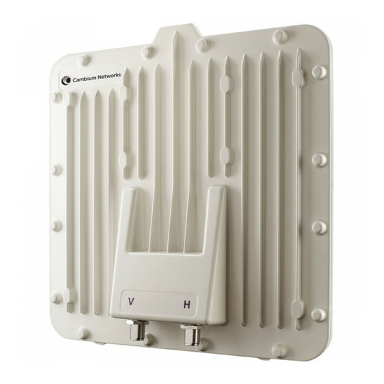
PTP 250 User Guide Outdoor unit (ODU) Outdoor unit (ODU) This section describes the PTP 250 ODU and its interfaces. ODU description The ODU is a self-contained unit that houses both radio and networking electronics. The ODU is supplied in two configurations: integrated (attached to its own flat plate antenna, Figure 1-2) or connectorized (without an antenna, Figure... -
Page 34: Odu Interfaces
Outdoor unit (ODU) Chapter 1: Product description Connectorized variant The connectorized ODU is designed to work with externally mounted antennas that have higher gains than the integrated antenna. Connectorized units can cope with more difficult radio conditions, as described in When to install connectorized units on page 2-12. -
Page 35: Connectorized Odu Antenna Interfaces
PTP 250 User Guide Outdoor unit (ODU) Connectorized ODU antenna interfaces The connectorized ODU also has interfaces to connect to an external antenna (Figure 1-5) via an N type connector with RF cable of type LMR100, LMR200, LMR300, LMR400 or LMR600. -
Page 36: Further Reading On The Odu
PTP 250 installation, including the ODU. • Ordering components on page 2-24 lists the components required for PTP 250 installations, including ODUs, with Motorola part numbers. • ODU specifications on page contains specifications of the ODU such as dimensions, weight and environmental requirements. -
Page 37: Power Over Ethernet Injector (Poe Power Supply)
2-6. PoE power supply description The Motorola High Power Gigabit PoE power supply (Motorola part number WB3727) (Figure 1-6) is a single-port Power over Ethernet injector combining low-voltage DC with Ethernet data in a single cable connecting to a PTP 250 ODU. -
Page 38: Poe Features
Power over Ethernet injector (PoE power supply) Chapter 1: Product description PoE features The PoE power supply has the following features: • Independent power controller (SPEAR™), CPU controller and input (Data) and output (Data & Power) shielded RJ-45 connectors. • Supports standard 10/100/1000BaseT Ethernet networks over a standard TIA/EIA-568 Category 5 (or higher) cabling. -
Page 39: Table 1-2 Poe Power Supply Interface Functions
PTP 250 User Guide Power over Ethernet injector (PoE power supply) Table 1-2 PoE power supply interface functions Interface Function IEC Power socket at rear Mains power input (100 – 240 V AC). DATA & POWER OUT RJ45 socket for connecting CAT5e cable to ODU. DATA IN RJ45 socket for connecting CAT5e cable to network. -
Page 40: Further Reading On The Poe Power Supply
• Ordering components on page 2-24 lists the components required for PTP 250 installations, including PoE power supply units, with Motorola part numbers. • Power supply unit specifications on page contains specifications of the PoE power supply (and the PIDU) such as dimensions, weight, environmental and electrical requirements. -
Page 41: Cabling And Lightning Protection
PTP 250 User Guide Cabling and lightning protection Cabling and lightning protection This section describes the cabling and lightning protection components of PTP 250 installations. PTP and lightning protection The PoE power supply meets the low level static discharge specifications identified in Electromagnetic compatibility (EMC) compliance on page but does not provide... -
Page 42: Indoor Connections
Cabling and lightning protection Chapter 1: Product description Indoor connections The CAT5e cable that connects the PoE power supply to the network equipment must meet the following requirements: • Screening: Must be either foil screen (FTP) or braided screen (STP) cable. •... -
Page 43: Lightning Protection Units (Lpus)
PTP 250 User Guide Cabling and lightning protection Lightning protection units (LPUs) One LPU kit (Figure 1-9) is required for each ODU drop cable. The LPU is installed at the building entry point. Figure 1-9 LPU kit phn-2182_003v004 (Oct 2011) 1-15 UNDER DEVELOPMENT... -
Page 44: Further Reading On Cabling And Lightning Protection
Cabling and lightning protection Chapter 1: Product description Further reading on cabling and lightning protection For more information on cabling and lightning protection, refer to the following: • Maximum cable lengths on page gives maximum permitted lengths of interface cables in PTP 250 installations. •... -
Page 45: Wireless Operation
PTP 250 User Guide Wireless operation Wireless operation This section describes how PTP 250 wireless links are operated, including modulation modes, power control and security. Wireless Transmissions The PTP 250 uses Time Division Duplexing (TDD) transmission, which means that a single frequency channel is used for both Transmit and Receive. -
Page 46: Mimo
Wireless operation Chapter 1: Product description PTP LINKPlanner includes an estimate of mean data rate, the data rate provided by each modulation and the percentage of time spent in each modulation mode. MIMO Multiple-Input Multiple-Output (MIMO) techniques provide protection against fading and increase the probability that the receiver will decode a usable signal. -
Page 47: Radar Avoidance
PTP 250 User Guide Wireless operation Radar avoidance In regions where protection of radars is part of the local regulations, the PTP 250 must detect interference from radar-like systems and avoid co-channel operation with these systems. To meet this requirement, the PTP 250 implements the following features: ETSI regulations The regulations have radar detection requirements for both master and slave devices. -
Page 48: Security
Wireless operation Chapter 1: Product description The requirements for a slave device are: • The slave device can only transmit after receiving a transmission from its associated master to demonstrate that the channel is an available channel. • The slave device is required to vacate the channel when the master device has detected a radar signal. -
Page 49: Using Frequency Planning
Using several different channels • Separating units located on the same mast • Using high performance (directional) external antennas For help with planning networks, refer to Chapter 2: Planning considerations, or contact a Motorola distributor or re-seller. phn-2182_003v004 (Oct 2011) 1-21 UNDER DEVELOPMENT... -
Page 50: Further Reading On Wireless Operation
Wireless operation Chapter 1: Product description Further reading on wireless operation For information on planning wireless operation, refer to the following: • Regulatory planning on page describes the regulatory restrictions that affect radio spectrum usage, such as frequency range and radar avoidance. •... -
Page 51: Ethernet Bridging
PTP 250 User Guide Ethernet bridging Ethernet bridging This section describes how the PTP 250 controls Ethernet data in the customer and management networks. Customer network Transparent Ethernet service The PTP 250 provides an Ethernet service between the Ethernet port at a local ODU and the Ethernet port at an associated remote ODU. -
Page 52: Management Network
Ethernet bridging Chapter 1: Product description Management network IP interface The PTP 250 ODU contains an embedded management agent with a single IP interface. Network management communication is exclusively based on IP and associated higher layer transport and application protocols. The factory default IP address of the management agent is 169.254.1.1. -
Page 53: Protocol Model
PTP 250 User Guide Ethernet bridging Protocol model Ethernet bridging behavior at each end of the wireless link is equivalent to a two-port, managed, transparent MAC bridge where the two ports are: • Ethernet Port • Wireless Port Frames are transmitted at the Wireless port over a proprietary point-to-point circuit-mode link layer between ends of the link. -
Page 54: Further Reading On Ethernet Bridging
Ethernet bridging Chapter 1: Product description Figure 1-11 Protocol layers between external interfaces and the management agent Further reading on Ethernet bridging For more information on Ethernet bridging, refer to the following: • Data network planning on page 2-23 describes factors to be considered when planning PTP 250 data networks. -
Page 55: System Management
PTP 250 User Guide System management System management This section introduces the PTP 250 management system, including the web interface, installation, configuration, alerts and upgrades. Web server The PTP 250 management agent contains a web server. Web-based management offers a convenient way to manage the equipment from a locally connected computer or from a workstation connected through a management network, without requiring any special management software. -
Page 56: Firmware Upgrade
PTP 250 firmware images are digitally signed, and the ODU will accept only images that contain a valid Motorola PTP digital signature. The ODU always requires a reboot to complete a firmware upgrade. Obtain the application firmware and this user guide from the support website (http://www.motorola.com/ptp/support) BEFORE warranty expires. - Page 57 PTP 250 data networks. • Ordering components on page 2-24 describes how to select components for a planned PTP 250 link (as an alternative to PTP LINKPlanner). It specifies Motorola part numbers for PTP 250 components. phn-2182_003v004 (Oct 2011) UNDER DEVELOPMENT...
-
Page 58: Chapter 2: Planning Considerations
Regulatory planning Chapter 2: Planning considerations Regulatory planning This section describes how to plan PTP 250 links to conform to the regulatory restrictions that apply in the country of operation. It is the responsibility of the user to ensure that the PTP product is operated in accordance with local regulatory limits. -
Page 59: Conforming To The Limits
PTP 250 User Guide Regulatory planning Conforming to the limits When a new PTP 250 unit is first accessed via the web interface, the user is required to select the Country Code from a list. Generally, the PTP 250 firmware does not allow the unit to be configured to operate outside the regulatory limits that apply to the selected country. -
Page 60: Frequency Selection
Regulatory planning Chapter 2: Planning considerations Frequency selection The PTP 250 fully conforms to regional regulatory requirements for radar avoidance. In regions that mandate DFS, the unit first ensures that there is no radar activity on a given channel for a period of 60 seconds before radiating on that channel. Once a channel has been selected for operation, the unit will continually monitor for radar activity on the operating channel. -
Page 61: Avoidance Of Weather Radars (Usa Only)
PTP 250 User Guide Regulatory planning Avoidance of weather radars (USA only) KDB 443999: Interim Plans to Approve UNII Devices Operating To comply with FCC rules ( in the 5470 - 5725 MHz Band with Radar Detection and DFS Capabilities ), units which are installed within 35 km of a Terminal Doppler Weather Radar (TDWR) system (or have a line of sight propagation path to such a system) must be configured to avoid any frequency... -
Page 62: Site Planning
Site planning Chapter 2: Planning considerations Site planning This section describes factors to be taken into account when choosing sites for the ODU and PoE power supply. ODU site selection When selecting a site for the ODU, consider the following factors: •... -
Page 63: Maximum Cable Lengths
PTP 250 User Guide Site planning Maximum cable lengths The maximum permitted lengths of interface cables in PTP 250 installations are specified Table 2-3. Table 2-3 Maximum cable lengths Interface type Interface Maximum length Ethernet power ODU to network terminating equipment. 100 m (330 ft) and data Wind loading... -
Page 64: Table 2-4 Lateral Force - Metric
Site planning Chapter 2: Planning considerations The lateral force produced by a single PTP 250 ODU (integrated or connectorized model) at different wind speeds is shown in Table 2-4. Table 2-4 Lateral force – metric Type of ODU Largest Lateral force (Kg) at wind speed surface area (meters per second) (square meters) -
Page 65: Wind Speed Statistics
PTP 250 User Guide Site planning Capabilities of the PTP 250 The structure and mounting brackets of the ODU are capable of withstanding wind speeds up to 242 kph (151 mph). Ensure that the structure to which the ODU is fixed is also capable of withstanding the prevalent wind speeds and loads. -
Page 66: Link Planning
When higher gain connectorized antennas are used, reduce the transmit power to ensure that the receiver signal level does not exceed -20 dBm. PTP LINKPlanner The Motorola PTP LINKPlanner software and user guide may be downloaded from http://www.motorola.com/ptp/support. PTP LINKPlanner imports path profiles and predicts data rates and reliability over the path. -
Page 67: Path Loss Considerations
PTP 250 User Guide Link planning Path loss considerations Path loss is the amount of attenuation the radio signal undergoes between the two ends of the link. Calculating path loss The path loss is the sum of the attenuation of the path if there were no obstacles in the way (Free Space Path Loss), the attenuation caused by obstacles (Excess Path Loss) and a margin to allow for possible fading of the radio signal (Fade Margin). -
Page 68: Planning For Connectorized Units
Planning for connectorized units Chapter 2: Planning considerations Planning for connectorized units This section describes factors to be taken into account when planning to use connectorized ODUs with external antennas in PTP 250 links. When to install connectorized units The majority of radio links can be successfully deployed with the integrated PTP 250. However the integrated units may not be sufficient in some areas, for example: •... -
Page 69: Calculating Maximum Power Level For Connectorized Units
PTP 250 User Guide Planning for connectorized units Calculating maximum power level for connectorized units If a connectorized PTP 250 link is to be installed in a country that imposes an EIRP limit in the 5.4 GHz or 5.8 GHz band, choose an external antenna and RF cable that will not cause the PTP 250 to exceed the EIRP limit. -
Page 70: Calculating Rf Cable Length (5.8 Ghz Fcc Only)
Planning for connectorized units Chapter 2: Planning considerations Calculating RF cable length (5.8 GHz FCC only) The 5.8 GHz band FCC approval for the product is based on tests with a cable loss between the ODU and antenna of not less than 1.2 dB. If cable loss is below 1.2 dB with a 6 ft diameter external antenna, the connectorized PTP 250 may exceed the maximum radiated spurious emissions allowed under FCC 5.8 GHz rules. -
Page 71: Grounding And Lightning Protection
The actual degree of protection required depends on local conditions and applicable local regulations. Motorola recommends that PTP 250 installation is contracted to a professional installer. -
Page 72: Lightning Protection Zones
Grounding and lightning protection Chapter 2: Planning considerations Lightning protection zones The ‘rolling sphere method’ (Figure 2-1) is used to determine where it is safe to mount equipment. An imaginary sphere, typically 50 meters in radius, is rolled over the structure. -
Page 73: General Protection Requirements
PTP 250 User Guide Grounding and lightning protection General protection requirements To adequately protect a PTP 250 installation, both ground bonding and transient voltage surge suppression are required. Basic requirements The following basic protection requirements must be implemented: • The ODU must be in ‘Zone B’ (see Lightning protection zones on page 2-16). -
Page 74: Protection Requirements For A Mast Or Tower Installation
Grounding and lightning protection Chapter 2: Planning considerations Figure 2-2 Grounding cable minimum bend radius and angle Radius not less than 203 mm (8 in) Angle not less than 90° ODU requirements The following ODU protection requirements must be implemented: •... -
Page 75: Figure 2-3 Grounding And Lightning Protection On Mast Or Tower
PTP 250 User Guide Grounding and lightning protection Figure 2-3 Grounding and lightning protection on mast or tower Outdoor CAT5e cable: gel-filled, shielded with copper-plated steel CAT5e cable: foil or braid screened, with screened connectors PTP 250 ground cable First point of contact with tower Tower/building ground system Mid-point of tower Equipment building... -
Page 76: Protection Requirements For A Wall Installation
Grounding and lightning protection Chapter 2: Planning considerations Protection requirements for a wall installation If the ODU is to be mounted on the wall of a building, then in addition to the general protection requirements (above), the following requirements must be observed: •... -
Page 77: Protection Requirements On A High Rise Building
PTP 250 User Guide Grounding and lightning protection Protection requirements on a high rise building If the ODU is to be mounted on a high rise building, it is likely that cable entry is at roof level (Figure 2-5) and the equipment room is several floors below (Figure 2-6). -
Page 78: Figure 2-6 Grounding And Lightning Protection Inside High Building
Grounding and lightning protection Chapter 2: Planning considerations Protection inside a high rise building The following protection requirements must be observed inside multi-story or high rise buildings (Figure 2-6): • The drop cable shield must be bonded to the building grounding system at the entry point to the building. -
Page 79: Data Network Planning
PTP 250 User Guide Data network planning Data network planning This section describes factors to be considered when planning PTP 250 data networks. IP interface Choose an IP address for the IP interface of the ODU management agent. The IP address must be unique and valid for the connected network segment. -
Page 80: Ordering Components
Chapter 2: Planning considerations Ordering components This section describes describes how to select components for a planned PTP 250 link (as an alternative to PTP LINKPlanner). It specifies Motorola part numbers for PTP 250 components. PTP 250 kits The PTP 250 is supplied as a 'Link' or an 'End' kit. A ‘Link’ kit contains components for both ends of a link (including two ODUs and two PoE power supply units). -
Page 81: Table 2-9 Inventory For Odu And Poe Power Supply Kits
PTP 250 User Guide Ordering components Table 2-9 Inventory for ODU and PoE power supply kits Item Notes ODUs ODUs may be Integrated (as illustrated) or Connectorized. ‘End Complete’ kit contains one ODU with grounding cable. ‘Link Complete’ kit contains two ODUs with grounding cables. - Page 82 Ordering components Chapter 2: Planning considerations Item Notes Mounting bracket assembly ‘End Complete’ kit contains one bracket. ‘Link Complete’ kit contains two brackets. Choice of mains leads (US, UK and ‘End Complete’ kit contains one US, one UK and one EU lead. ‘Link Complete’...
-
Page 83: Other Standard Components
Table 2-10 Additional inventory for standard installations Item Notes Outdoor drop cable Superior Essex BBDGe cable is available from Motorola with the following lengths and part numbers (other lengths are available from Superior Essex): ‘1000 ft Reel Outdoor Copper Always use Cat5e cable that is gel-filled and Clad CAT5E’. - Page 84 Notes Cable grounding kits One kit is required per drop cable grounding point. ‘Cable Grounding Kits For 1/4" And 3/8" Cable’. Motorola part number 01010419001. Kit contents: grounding cable, self- amalgamating tape, PVC tape, tie- wraps, bolts, washers and nuts.
-
Page 85: Components Required With Connectorized Odus
For connecting the ODU to the antenna. May be cable of type LMR100, LMR200, LMR300, LMR400 or LMR600. LMR400 is supplied by Motorola: ‘50 Ohm Braided Coaxial Cable - 75 meter’. Motorola part number 30010194001. ‘50 Ohm Braided Coaxial Cable - 500 meter’. Motorola part number 30010195001. - Page 86 ‘RF CONNECTOR,N,MALE,STRAIGHT FOR CNT-400 CABLE’. Motorola part number 09010091001. For the antenna end of the RF cable, refer to the antenna manufacturer’s instructions. Self-amalgamating and PVC tape To weatherproof the RF connectors.
-
Page 87: Table 2-12 Allowed Antennas For Deployment In Usa/Canada - 5.4 Ghz
PTP 250 User Guide Ordering components Table 2-12 Allowed antennas for deployment in USA/Canada – 5.4 GHz Manufacturer Antenna Type Gain (dBi) RadioWaves Radio Waves 1.5-foot Parabolic, SP1.5-5.2 (25.3dBi) 25.3 RadioWaves 14 inch square flat plate FP-24-5 23.5 MARS 15 inch (370mm) square flat plate MA WS55.27 26.0 Table 2-13 Allowed antennas for deployment in USA/Canada –... - Page 88 Ordering components Chapter 2: Planning considerations Manufacturer Antenna Type Gain Parabolic (dBi) Dish Gabriel Gabriel 6-foot High Performance Dual 37.3 QuickFire Parabolic, HQFD6-52-N Gabriel Gabriel 2-foot Standard QuickFire 28.5 Parabolic, QF2-52-N Gabriel Gabriel 2-foot Standard QuickFire 28.5 Parabolic, QF2-52-N-RK Gabriel Gabriel 2.5-foot Standard QuickFire 31.2 Parabolic, QF2.5-52-N...
- Page 89 PTP 250 User Guide Ordering components Manufacturer Antenna Type Gain Parabolic (dBi) Dish RadioWaves Radio Waves 4-foot Parabolic, SP4-5.2 34.8 (34.8 dBi) RadioWaves Radio Waves 6-foot Dual-Pol Parabolic, 37.5 SPD6-5.2 (37.5 dBi) RadioWaves Radio Waves 2-foot Parabolic, SP2-2/5 28.3 (28.3 dBi) RadioWaves Radio Waves 3-foot Parabolic, SP3-2/5 31.4...
-
Page 90: Alternative Components
It provides an interface to a -48 V DC power supply. ‘PTP 300/500/600 Series PIDU with AUS Lead’, Motorola part number WB3022. ‘PTP 300/500/600 Series PIDU with EU Lead’, Motorola part number WB3023. ‘PTP 300/500/600 Series PIDU with UK Lead’, Motorola part number WB3024. -
Page 91: Chapter 3: Legal Information
Any such modifications could void the user’s authority to operate the equipment and will void the manufacturer’s warranty. The following topics are described in this chapter: • Motorola Solutions, Inc. end user license agreement on page • Hardware warranty on page •... -
Page 92: Motorola Solutions, Inc. End User License Agreement
Motorola Solutions, Inc. end user license agreement In connection with Motorola’s delivery of certain proprietary software or products containing embedded or pre-loaded proprietary software, or both, Motorola is willing to license this certain proprietary software and the accompanying documentation to you only on the condition that you accept all the terms in this End User License Agreement (“Agreement”). -
Page 93: Conditions Of Use
Documentation is in electronic form, you may print out 1 copy, which then may not be copied. With regard to the copy made for backup or archival purposes, you agree to reproduce any Motorola copyright notice, and other proprietary legends appearing thereon. Such copyright notice(s) may appear in any of several forms, including machine-readable form, and you agree to reproduce such notice in each form in which it appears, to the extent it is physically possible to do so. -
Page 94: Title And Restrictions
Software and Documentation and any copies made by you remain with Motorola and its licensors. You will not, and will not permit others to: (i) modify, translate, decompile, bootleg, reverse engineer, disassemble, or extract the inner workings of the Software or Documentation, (ii) copy the look-and-feel or functionality of the Software or Documentation;... -
Page 95: Right To Use Motorola's Name
Except as required in “Conditions of use”, you will not, during the term of this Agreement or thereafter, use any trademark of Motorola, or any word or symbol likely to be confused with any Motorola trademark, either alone or in any combination with another word or words. -
Page 96: Disclaimer
THE TOTAL LIABILITY OF MOTOROLA UNDER THIS AGREEMENT FOR DAMAGES WILL NOT EXCEED THE TOTAL AMOUNT PAID BY YOU FOR THE PRODUCT LICENSED UNDER THIS AGREEMENT. IN NO EVENT WILL MOTOROLA BE LIABLE IN ANY WAY FOR INCIDENTAL, CONSEQUENTIAL, INDIRECT, SPECIAL OR PUNITIVE DAMAGES OF... -
Page 97: Term Of License
Agreement by you. Within 30 days after termination of this Agreement, you will certify to Motorola in writing that through your best efforts, and to the best of your knowledge, the original and all copies, in whole or in part, in any form, of the Software and all related material and Documentation, have been destroyed, except that, with prior written consent from Motorola, you may retain one copy for archival or backup purposes. - Page 98 PTP 250 product. To gain access to source code licensed under the GPL, please contact Motorola via the support web site at www.Motorola.com/ptp/support/contact. phn-2182_003v004 (Oct 2011)
-
Page 99: Hardware Warranty
Hardware warranty Hardware warranty Motorola’s standard hardware warranty is for one (1) year from date of shipment from Motorola or a Motorola Point-to-Point Distributor. Motorola warrants that hardware will conform to the relevant published specifications and will be free from material defects in material and workmanship under normal use and service. -
Page 100: Limit Of Liability
Chapter 3: Legal information Limit of liability IN NO EVENT SHALL MOTOROLA BE LIABLE TO YOU OR ANY OTHER PARTY FOR ANY DIRECT, INDIRECT, GENERAL, SPECIAL, INCIDENTAL, CONSEQUENTIAL, EXEMPLARY OR OTHER DAMAGE ARISING OUT OF THE USE OR INABILITY TO USE THE PRODUCT... - Page 101 PTP 250 User Guide Chapter 4: Reference information This chapter describes the reference information and regulatory notices that apply to the PTP 250. The following reference topics are contained in this chapter: • Equipment specifications on page contains specifications of the ODU and power supply unit that are required for PTP 250 installations.
-
Page 102: Chapter 4: Reference Information
Equipment specifications Chapter 4: Reference information Equipment specifications This section contains specifications of the ODU and power supply unit that are required for PTP 250 installations. ODU specifications The ODU conforms to the specifications listed in Table 4-1, Table 4-2 Table 4-3. -
Page 103: Power Supply Unit Specifications
PTP 250 User Guide Equipment specifications Power supply unit specifications The power supply units conform to the specifications listed in Table 4-4, Table 4-5, Table Table 4-7. Table 4-4 Power supply unit physical specifications Category PoE power supply PIDU Dimensions 88 mm x 51 mm x 166 mm 250 mm x 40 mm x 80 mm (3.5 ins x 2 ins x 6.5 ins) -
Page 104: Table 4-7 Poe Power Supply Ethernet Interface Specifications
Equipment specifications Chapter 4: Reference information Table 4-7 PoE power supply Ethernet interface specifications Category PoE power supply Input (Data In) Ethernet 10/100/1000 Base-T (RJ-45 female socket) Output (Data & Power Out) Ethernet 10/100/1000 Base-T, plus 55 V DC (nominal) RJ-45 female socket, with DC voltage on pairs 7-8 (-) and 4-5 (+) User Port Power: 30 Watts Max... -
Page 105: Wireless Specifications
PTP 250 User Guide Wireless specifications Wireless specifications This section contains specifications of the PTP 250 wireless interface. These specifications include RF bands, channel width and link loss. General wireless specifications Table 4-8 contains radio system specifications for the 5.4 GHz band. Table 4-9 contains radio system specifications for the 5.8 GHz band. -
Page 106: Table 4-9 5.8 Ghz Rf Specifications
Wireless specifications Chapter 4: Reference information Table 4-9 5.8 GHz RF specifications Radio technology Specification RF band 5.725-5.850 GHz Channel selection By dynamic frequency control and manual intervention Automatic detection on start-up and continual adaptation. Dynamic frequency control Initial capture 10-15 sec. Out of service on interference 100 ms. -
Page 107: Data Network Specifications
PTP 250 User Guide Data network specifications Data network specifications This section contains specifications of the PTP 250 Ethernet interface. Ethernet interfaces The PTP 250 Ethernet ports conform to the specifications listed in Table 4-10. Table 4-10 Ethernet bridging specifications Ethernet bridging Specification Protocol... -
Page 108: Compliance With Safety Standards
Compliance with safety standards Chapter 4: Reference information Compliance with safety standards This section lists the safety specifications against which the PTP 250 has been tested and certified. It also describes how to keep RF exposure within safe limits. Electrical safety compliance The PTP 250 hardware has been tested for compliance to the electrical safety specifications listed in Table... -
Page 109: Human Exposure To Radio Frequency Energy
PTP 250 User Guide Compliance with safety standards Human exposure to radio frequency energy Relevant standards (USA and EC) applicable when working with RF equipment are: • ANSI IEEE C95.1-1991, IEEE Standard for Safety Levels with Respect to Human Exposure to Radio Frequency Electromagnetic Fields, 3 kHz to 300 GHz. •... -
Page 110: Calculated Distances And Power Compliance Margins
Compliance with safety standards Chapter 4: Reference information The following calculation is based on the ANSI IEEE C95.1-1991 method, as that provides a worst case analysis. Details of the assessment to EN50383:2002 can be provided, if required. Peak power density in the far field of a radio frequency point source is calculated as follows: π... -
Page 111: Table 4-13 Power Compliance Margins
PTP 250 User Guide Compliance with safety standards Table 4-13 Power compliance margins Band Antenna Tx Burst P (W) d (m) R (m) (W/m 5.4 GHz Integrated 0.0050 0.0050 0.089 Max gain 0.0025 0.0025 0.089 connectorized ETSI Integrated 0.0200 0.0200 0.178 5.8 GHz Max gain... -
Page 112: Compliance With Radio Regulations
Compliance with radio regulations This section describes how the PTP 250 complies with the radio regulations that are in force in various countries. Changes or modifications not expressly approved by Motorola could void the user’s authority to operate the system. Type approvals This system has achieved Type Approval in various countries around the world. -
Page 113: Fcc And Etsi Compliance Testing
A Class B Digital Device is a device that is marketed for use in a residential environment, notwithstanding use in commercial, business and industrial environments. Notwithstanding that Motorola has designed (and qualified) the PTP 250 products to generally meet the Class B requirement to minimize the potential for interference, the PTP 250 product ranges are not marketed for use in a residential environment. -
Page 114: Notifications
Hereby, Motorola Solutions, Inc. declares that the 5.4 GHz products comply with the essential requirements and other relevant provisions of Directive 1999/5/EC. The declaration of conformity http://www.motorola.com/ptp/support. -
Page 115: 5.8 Ghz Fcc And Ic Notification
PTP 250 User Guide Notifications 5.8 GHz FCC and IC notification This system has achieved Type Approval in various countries around the world. This means that the system has been tested against various local technical regulations and found to comply. The frequency band in which the system operates is ‘license exempt’ and the system is allowed to be used provided it does not cause interference. -
Page 116: 5.8 Ghz European Union Notification
Notifications Chapter 4: Reference information Industry Canada (IC) This Class B digital apparatus complies with Canadian ICES-003. Cet appareil numérique de la classe B conforme á la norme NMB-003 du Canada. RSS-GEN issue 3 (7.1.3) Licence-Exempt Radio Apparatus: This device complies with Industry Canada license-exempt RSS standard(s). Operation is subject to the following two conditions: (1) this device may not cause interference, and (2) this device must accept any interference, including interference that may cause undesired operation of the device. -
Page 117: Figure 4-3 European Union Certification On 5.8 Ghz Product Label
Hereby, Motorola Solutions, Inc. declares that the PTP 250 products comply with the essential The declaration of conformity requirements and other relevant provisions of Directive 1999/5/EC. - Page 118 Notifications Chapter 4: Reference information phn-2182_003v004 (Oct 2011) 4-18 UNDER DEVELOPMENT...
- Page 119 PTP 250 User Guide Chapter 5: Installation This chapter describes how to install the PTP 250 hardware, To install the equipment at each PTP 250 link end, perform these tasks: • Preparing for installation on page describes the checks to be performed before proceeding with the installation.
-
Page 120: Chapter 5: Installation
Preparing for installation Chapter 5: Installation Preparing for installation This section describes the checks to be performed before proceeding with the installation. Unit pre-configuration It is common practice to pre-configure the units during staging before site installation by performing the following tasks from Chapter 6: Configuration and alignment: •... -
Page 121: Selecting Installation Options
2-10 Preparing personnel IN NO EVENT SHALL MOTOROLA SOLUTIONS, INC. BE LIABLE FOR ANY INJURY TO ANY PERSONS OR ANY DAMAGE CAUSED DURING THE INSTALLATION OF THE MOTOROLA PTP 250. Ensure that only qualified personnel undertake the installation of a PTP 250 link. -
Page 122: Installing The Odu
Installing the ODU Chapter 5: Installation Installing the ODU Perform this task to install the ODU (integrated or connectorized) on the supporting structure. This task consists of the following procedures: • Checks and safety precautions on page • Selecting a position for the ODU (connectorized) on page •... -
Page 123: Figure 5-1 Checking The Odu Before Mounting
PTP 250 User Guide Installing the ODU Check that the ODU is pre-fitted with a mounting bracket (designed to ease installation) and with a ground cable (Figure 5-1). Figure 5-1 Checking the ODU before mounting Do not mount the ODU on poles with diameter less than 50mm (2”) or greater than 75mm (3”). -
Page 124: Selecting A Position For The Odu (Connectorized)
Installing the ODU Chapter 5: Installation Selecting a position for the ODU (connectorized) If the ODU is connectorized, select a mounting position that gives it maximum protection from the elements, but still allows easy access for connecting and weatherproofing the cables. - Page 125 PTP 250 User Guide Installing the ODU Connect the ODU ground cable to the to the supporting structure grounding point, within 0.3 meters (1 ft) of the ODU bracket and on the same metal (if necessary, remove paint and apply anti-oxidant compound first). Do not attach grounding cables to the ODU mounting bracket bolts, as this arrangement will not provide full protection.
-
Page 126: Installing Connectorized Antennas
Installing connectorized antennas Chapter 5: Installation Installing connectorized antennas If the ODU is connectorized, perform this task to install separate antenna(s). Preparing for connectorized installations Before proceeding with the installation, perform the following checks: • Check that the correct components are available, as described in Ordering components on page 2-24. -
Page 127: Figure 5-2 Lightning Arrestor Mounting
PTP 250 User Guide Installing connectorized antennas If the ODU is mounted outdoors, weatherproof the N type connectors fitted to the ODU by following the procedure Weatherproofing an N type connector on page 12. Weatherproof the antenna joints in the same way (unless the antenna manufacturer specifies a different method). -
Page 128: Figure 5-3 Polyphaser Assembly
Installing connectorized antennas Chapter 5: Installation Figure 5-3 Polyphaser assembly phn-2182_003v004 (Oct 2011) 5-10 UNDER DEVELOPMENT... -
Page 129: Figure 5-4 Grounding Points For Antenna Cables
PTP 250 User Guide Installing connectorized antennas Figure 5-4 Grounding points for antenna cables phn-2182_003v004 (Oct 2011) 5-11 UNDER DEVELOPMENT... -
Page 130: Weatherproofing An N Type Connector
Installing connectorized antennas Chapter 5: Installation Weatherproofing an N type connector The following procedure should be used to weatherproof the N type connectors fitted to the connectorized ODU and antenna (if recommended by the antenna manufacturer). N type connectors should be tightened using a torque wrench, set to 15 lb in or 1.7 Nm. If a torque wrench is not available, N type connectors may be finger tightened. - Page 131 PTP 250 User Guide Installing connectorized antennas Cut a 125mm (5 inches) length of rubber tape (self amalgamating): Expand the width of the tape by stretching it so that it will wrap completely around the connector and cable: Press the tape edges together so that there are no gaps. The tape should extend 25mm (1inch) beyond the PVC tape: phn-2182_003v004 (Oct 2011) 5-13...
- Page 132 Installing connectorized antennas Chapter 5: Installation Wrap a layer of 50 mm (2 inch) PVC tape from bottom to top, starting from 25 mm (1 inch) below the edge of the self-amalgamating tape, overlapping at half width. Repeat with a further four layers of 19 mm (0.75 inch) PVC tape, always overlapping at half width.
-
Page 133: Installing The Drop Cable And Lpu
PTP 250 User Guide Installing the drop cable and LPU Installing the drop cable and LPU Perform this task to install the drop cable from the ODU to the PoE power supply, and to provide grounding and lightning protection for the installation. This task consists of the following procedures: •... -
Page 134: Preparing Drop Cables
Perform this task to prepare the CAT5e cables that connect the ODU to the PoE power supply. Always use Cat5e cable that is gel-filled and shielded with copper-plated steel. Alternative types of cable are not supported by Motorola. The maximum permitted lengths of CAT5e cables are specified in Maximum cable lengths on page 2-7. -
Page 135: Assembling An Rj45 Connector And Gland
PTP 250 User Guide Installing the drop cable and LPU ‘LPU-PoE’ cable: To prepare a short section of cable to connect the LPU to the PoE power supply, proceed as follows: Cut off the approximate length required (allowing a bit of surplus). Fit an RJ45 connector and gland to the top end only, as described in Assembling an RJ45 connector and gland... -
Page 136: Figure 5-6 Correct Cable Preparation For Drop Cable Of The Supported Type
Installing the drop cable and LPU Chapter 5: Installation Figure 5-6 Correct cable preparation for drop cable of the supported type Check that the crimp tool matches the RJ45 connector being used; otherwise the cable or connector may be damaged. The cable inner sheath must be located correctly under the connector housing tang. -
Page 137: Installing And Grounding The Main Drop Cable
PTP 250 User Guide Installing the drop cable and LPU Figure 5-7 Drop cable with RJ45 and gland Installing and grounding the main drop cable Perform this procedure to install the main drop cable, connect it to the ODU, and ground it to the supporting structure. -
Page 138: Connecting An Rj45 And Gland To A Unit
Installing the drop cable and LPU Chapter 5: Installation Connecting an RJ45 and gland to a unit Perform this task to connect the drop cable to an ODU or LPU. This procedure contains illustrations of an ODU, but it applies in principle to both the ODU and the LPU. To connect the drop cable with a gland to a unit (LPU or ODU), proceed as follows: Insert the RJ45 plug into the socket in the unit, making sure that the locking tab snaps home. - Page 139 PTP 250 User Guide Installing the drop cable and LPU When the gland body has been fitted, tighten the gland back shell. Do not over-tighten the gland back shell, as the internal seal and structure may be damaged. The following example shows correctly tightened and over-tightened gland back shells: phn-2182_003v004 (Oct 2011) 5-21...
-
Page 140: Disconnecting An Rj45 And Gland From A Unit
Installing the drop cable and LPU Chapter 5: Installation Disconnecting an RJ45 and gland from a unit Perform this task to disconnect the drop cable from an ODU or LPU. This procedure contains illustrations of an ODU, but it applies in principle to both the ODU and the LPU. To disconnect the drop cable with a gland from a unit (LPU or ODU), proceed as follows: Remove the gland back shell. -
Page 141: Making A Drop Cable Ground Point
Ground cables must be installed without drip loops and pointing down towards the ground; otherwise they may not be effective. To ground the drop cable to a metal structure using the Motorola grounding kit (part number 01010419001), proceed as follows: Remove 60 mm (2.5 inches) of the drop cable outer sheath. - Page 142 Installing the drop cable and LPU Chapter 5: Installation Fold the ground wire strap around the drop cable screen and fit cable ties. Tighten the cable ties with pliers. Cut the surplus from the cable ties. Cut a 38mm (1.5 inches) section of self-amalgamating tape and wrap it completely around the joint between the drop and ground cables.
- Page 143 PTP 250 User Guide Installing the drop cable and LPU Use the remainder of the self-amalgamating tape to wrap the complete assembly. Press the tape edges together so that there are no gaps. Wrap a layer of PVC tape from bottom to top, starting from 25 mm (1 inch) below and finishing 25 mm (1 inch) above the edge of the self-amalgamating tape, over lapping at half width.
- Page 144 Installing the drop cable and LPU Chapter 5: Installation Repeat with a further four layers of PVC tape, always overlapping at half width. Wrap the layers in alternate directions: Second layer: top to bottom. Third layer: bottom to top. Fourth layer: top to bottom. Fifth layer: bottom to top.
-
Page 145: Installing And Grounding The Drop Cable At Building Entry
PTP 250 User Guide Installing the drop cable and LPU Installing and grounding the drop cable at building entry Perform this procedure to install and ground the drop cable and LPU at the building (or cabinet) entry point (Figure 5-8). Figure 5-8 Grounding at building entry phn-2182_003v004 (Oct 2011) 5-27... - Page 146 Installing the drop cable and LPU Chapter 5: Installation To run the drop cable into the building, proceed as follows: Make an entry point into the building and run the main drop cable into the building. Ground the drop cable to the external ground bar outside the building entry point, as described in Making a drop cable ground point on page 5-23.
-
Page 147: Installing The Poe Power Supply
PTP 300 and If the PIDU is to be installed rather than the PoE power supply, refer to the PTP 500 Series User Guide (available for download at www.motorola.com/ptp/software) for PIDU installation instructions. This task consists of the following procedures: •... -
Page 148: Mounting The Poe Power Supply
Installing the PoE power supply Chapter 5: Installation Mounting the PoE power supply To mount the PTP 250 PoE power supply: install two screws (Table 5-1) in the wall or shelf, then align the mounting slots (Figure 5-9) to capture the surface screws. Figure 5-9 Mounting slots on underside of PoE power supply Table 5-1 Screw dimensions for the PoE power supply phn-2182_003v004 (Oct 2011) -
Page 149: Connecting The Poe Power Supply To The Drop Cable
PTP 250 User Guide Installing the PoE power supply Connecting the PoE power supply to the drop cable The drop cable from the ODU is connected to the DATA & POWER OUT interface of the PoE power supply. Do not dress the PoE power supply cables too tightly, as this may make the connections unreliable. -
Page 150: Preparing The Poe Power Supply To Network Equipment Cable
Installing the PoE power supply Chapter 5: Installation Preparing the PoE power supply to network equipment cable Prepare the CAT5e cable that will connect the PoE power supply to the network equipment. This cable must meet the following requirements: • Use either foil screen (FTP) or braided screen (STP) cable. -
Page 151: Chapter 6: Configuration And Alignment
PTP 250 User Guide Chapter 6: Configuration and alignment This chapter describes all configuration and alignment tasks that are performed when a PTP 250 link is deployed. Before proceeding with unit configuration and antenna alignment, observe the precautions described in Preparing for configuration and alignment on page 6-2. -
Page 152: Preparing For Configuration And Alignment
Preparing for configuration and alignment Chapter 6: Configuration and alignment Preparing for configuration and alignment This section describes the checks to be performed before proceeding with unit configuration and antenna alignment. Safety precautions during configuration and alignment All national and local safety standards must be followed while configuring the units and aligning the antennas. -
Page 153: Connecting To The Unit
PTP 250 User Guide Connecting to the unit Connecting to the unit Perform this task to connect a management PC to the unit, power it up and open the web interface. This task consists of the following procedures: • Configuring the management PC on page •... -
Page 154: Figure 6-1 Ip Configuration On The Pc
Connecting to the unit Chapter 6: Configuration and alignment Figure 6-1 IP configuration on the PC Figure 6-2 Internet Protocol (TCP/IP) Properties page phn-2182_003v004 (Oct 2011) UNDER DEVELOPMENT... -
Page 155: Connecting To The Pc And Powering Up
PTP 250 User Guide Connecting to the unit Connecting to the PC and powering up Ensure AC power is supplied to the PoE power supply using an AC cable with an appropriate ground connection approved for the country of operation. To connect the ODU to the PC and power up the unit, proceed as follows: Check that the ODU and PoE power supply are correctly connected. -
Page 156: Logging Into The Web Interface
Start the web browser from the management PC. Type the IP address of the unit (factory default is 169.254.1.1) into the address bar. Press ENTER. For user security, Motorola digitally signs its applications. On the first login, the digital signature confirmation is displayed (Figure 6-4). -
Page 157: Figure 6-4 Digital Signature Confirmation (On First Login)
PTP 250 User Guide Connecting to the unit Figure 6-4 Digital signature confirmation (on first login) Figure 6-5 Digitally signed Java app splash screen phn-2182_003v004 (Oct 2011) UNDER DEVELOPMENT... -
Page 158: Figure 6-6 Login Page
Connecting to the unit Chapter 6: Configuration and alignment Figure 6-6 Login page Figure 6-7 Change Password page (on first login) phn-2182_003v004 (Oct 2011) UNDER DEVELOPMENT... -
Page 159: Figure 6-8 Set Country Code Page (On First Login)
PTP 250 User Guide Connecting to the unit Figure 6-8 Set Country Code page (on first login) Figure 6-9 Menu and System Summary page (on first login) phn-2182_003v004 (Oct 2011) UNDER DEVELOPMENT... -
Page 160: Upgrading Firmware Version
(Figure 6-10). Go to http://www.motorola.com/ptp/support and find Point-to-Point software updates. Check that the latest available firmware version (for example 250-04-01) is the same as the one already installed. If the unit needs to be upgraded to the latest firmware version, perform... -
Page 161: Uploading A New Firmware Version
On completion, the Upload Successful page is displayed (Figure 6-12). To ensure that only authorized Motorola firmware is installed, the unit checks the image for a DSA signature. If the DSA signature is missing or incorrect, an error message is displayed and the upload fails. -
Page 162: Figure 6-11 Firmware Update Page
Upgrading firmware version Chapter 6: Configuration and alignment Figure 6-11 Firmware Update page Figure 6-12 Upload Successful page phn-2182_003v004 (Oct 2011) 6-12 UNDER DEVELOPMENT... -
Page 163: Starting Installation Wizard
PTP 250 User Guide Using the installation wizard Using the installation wizard Perform this task to configure the LAN, wireless, date and email attributes of the unit. This task consists of the following procedures: • Starting installation wizard on page 6-13 •... -
Page 164: Step 1: Lan Configuration
Using the installation wizard Chapter 6: Configuration and alignment Step 1: LAN configuration Step 1 of the Installation wizard is for updating the LAN configuration (Figure 6-14). The attributes are described in Table 6-1. Update IP Address, Subnet Mask and Gateway IP Address to meet network requirements (as specified by the network administrator). -
Page 165: Table 6-1 Step 1: Lan Configuration Attributes
PTP 250 User Guide Using the installation wizard Table 6-1 Step 1: LAN Configuration attributes Attribute Meaning IP Address Internet protocol (IP) address. This address is used by the family of Internet protocols to uniquely identify this unit on a network. All units are shipped with a default IP address of 169.254.1.1. -
Page 166: Step 2: Wireless Configuration
Using the installation wizard Chapter 6: Configuration and alignment Step 2: Wireless configuration Step 2 of the Installation wizard is for updating the wireless configuration (Figure 6-15). The attributes are described in Table 6-2. Update the attributes as required and select Next. -
Page 167: Table 6-2 Step 2: Wireless Configuration Attributes
PTP 250 User Guide Using the installation wizard Table 6-2 Step 2: Wireless Configuration attributes Attribute Meaning System Name A name for the link. Spaces are not allowed, so use underscores instead. End Location The location of the link end. Spaces are not allowed, so use underscores instead. -
Page 168: Step 3: Date And Time Settings
Using the installation wizard Chapter 6: Configuration and alignment Attribute Meaning Cable Loss Loss (dB) in the RF cable between the ODU and the antenna. If there is a significant difference in length of the antenna cables for the two antenna ports, then enter the average value. Maximum Power The maximum power (dBm) at which the unit will transmit. -
Page 169: Figure 6-16 Step 3: Date And Time Settings Page
PTP 250 User Guide Using the installation wizard Figure 6-16 Step 3: Date and Time Settings page phn-2182_003v004 (Oct 2011) 6-19 UNDER DEVELOPMENT... -
Page 170: Table 6-3 Step 3: Date And Time Settings Attributes
Using the installation wizard Chapter 6: Configuration and alignment Table 6-3 Step 3: Date and Time Settings attributes Attribute Meaning Current Time The current date and time setting for this unit. To update this, select Set Date/Time. Time Zone The time zone in which this unit operates. Enable NTP If this is ticked, the PTP 250 will obtain accurate date and time updates from a networked time server. -
Page 171: Step 4: Email Configuration
PTP 250 User Guide Using the installation wizard Step 4: Email configuration Step 4 of the Installation wizard is for configuring email notifications (Figure 6-17). The Update the attributes as required and select Next. attributes are described in Table 6-4. Figure 6-17 Step 4: Email Configuration page Table 6-4 Step 4: Email Configuration attributes Attribute... -
Page 172: Step 5: Confirm Installation Configuration
Using the installation wizard Chapter 6: Configuration and alignment Step 5: Confirm installation configuration Step 5 of the Installation wizard is for reviewing and confirming the updated attributes (Figure 6-18). If any of the attributes are incorrect, select Back to return to previous steps and update them. -
Page 173: Aligning Antennas
PTP 250 User Guide Aligning antennas Aligning antennas Before performing this task, check that hardware installation is complete (apart from the network connections) at both the Master and Slave sites. This task consists of the following procedures: • Starting up the units on page 6-23 •... -
Page 174: Checking That The Units Are Armed
Aligning antennas Chapter 6: Configuration and alignment Checking that the units are armed Select menu option Home. The System Summary page is displayed. Check that the Wireless Link Status contains the word ‘Armed’ (Figure 6-19); this confirms that the units are ready for alignment. - Page 175 PTP 250 User Guide Aligning antennas To achieve best results, make small incremental changes to elevation and azimuth. The action of tightening the mounting bolts can alter antenna alignment. This can be helpful when fine-tuning alignment, but it can also lead to misalignment. To prevent misalignment, continue to monitor receive signal level during final tightening of the bolts.
-
Page 176: Aligning Separate Antennas For Spatial Diversity
Aligning antennas Chapter 6: Configuration and alignment Aligning separate antennas for spatial diversity If a connectorized ODU is installed at either site with two separate antennas for spatial diversity, proceed as follows: Connect the horizontal polarization antenna to the ODU, disconnect the vertical polarization antenna, and then perform Aligning antennas on page 6-24. -
Page 177: Table 6-5 Antenna Alignment Tones
PTP 250 User Guide Aligning antennas Antenna alignment tones This is the first method that may be used to monitor receive signal level during antenna alignment. The ODU emits audible tones during installation to assist with alignment. The pitch of the alignment tone is proportional to the received power of the wireless signals. -
Page 178: Figure 6-20 Graphical Alignment Page
Aligning antennas Chapter 6: Configuration and alignment Graphical alignment This is the second method that may be used to monitor receive signal level during antenna alignment. Select menu option Installation Wizard, Graphical Alignment. The Graphical Alignment page is displayed (Figure 6-20). -
Page 179: Disarming The Units
PTP 250 User Guide Aligning antennas Disarming the units When antenna alignment is complete, both units in the link must be disarmed before network connection. To disarm the units, select menu option Installation Wizard. The Step 5: Confirm 6-13). Select Set Disarmed, Yes to confirm and Configuration page is displayed (Figure then Back until the Step 1: LAN Configuration page is displayed. -
Page 180: Connecting Link To The Network
Connecting link to the network Chapter 6: Configuration and alignment Connecting link to the network When antenna alignment is complete, the link performance must be checked and then the link connected to the network for operational running. This task consists of the following procedures: •... -
Page 181: Figure 6-21 System Configuration Page
PTP 250 User Guide Connecting link to the network Figure 6-21 System Configuration page Figure 6-22 LAN Configuration page phn-2182_003v004 (Oct 2011) 6-31 UNDER DEVELOPMENT... -
Page 182: Figure 6-23 Date And Time Settings Page
Connecting link to the network Chapter 6: Configuration and alignment Figure 6-23 Date and Time Settings page phn-2182_003v004 (Oct 2011) 6-32 UNDER DEVELOPMENT... -
Page 183: Comparing Actual To Predicted Performance
PTP 250 User Guide Connecting link to the network Comparing actual to predicted performance For at least one hour of operation after disarming, monitor the link to check that it is achieving predicted levels of performance. To check performance, select menu option Status. The System Status page is displayed (Figure 6-24). -
Page 184: Connecting To The Network
Connecting link to the network Chapter 6: Configuration and alignment Connecting to the network To connect to the network, proceed as follows: Disconnect the local PC from the PoE power supply at the Master and Slave sites. At each site, connect the PoE power supply DATA IN ports to a router port, switch port or other network equipment in the data network (Figure 6-3) using... -
Page 185: Saving The System Configuration
PTP 250 User Guide Saving the system configuration Saving the system configuration Save the system configuration in the following situations: • After a new unit has been fully configured as described in this chapter. • After any change has been made to the configuration. •... - Page 186 Saving the system configuration Chapter 6: Configuration and alignment phn-2182_003v004 (Oct 2011) 6-36 UNDER DEVELOPMENT...
-
Page 187: Chapter 7: Operation
PTP 250 User Guide Chapter 7: Operation This chapter provides instructions for operators of the PTP 250 web user interface. The following topics are described in this chapter: • Web-based management on page describes the layout and the main menu options of the PTP 250 web-based management interface. -
Page 188: Web-Based Management
ENTER. When the login page is displayed (Figure 7-1), enter Username ‘admin’ and Password (factory default is ‘motorola’, but this must be changed at first login) and select Login. The Menu and System Summary are displayed (Figure 7-2). -
Page 189: Figure 7-2 Menu And System Summary Page (Wireless Link Up)
PTP 250 User Guide Web-based management Figure 7-2 Menu and System Summary page (wireless link up) phn-2182_003v004 (Oct 2011) UNDER DEVELOPMENT... -
Page 190: Using The Menu Options
Web-based management Chapter 7: Operation Using the menu options All web pages contain the menu navigation bar on the left hand side (Figure 7-3). The menu is used to navigate to other web pages. The currently selected option is always highlighted with a light blue background. -
Page 191: Table 7-1 Procedures Performed From Each Menu Option
PTP 250 User Guide Web-based management Table 7-1 Procedures performed from each menu option Menu option Procedures Home Viewing the system summary on page Managing link status and alerts on page 7-15 Checking that the units are armed on page 6-24 Status Viewing the system status... -
Page 192: Viewing The System Summary
Web-based management Chapter 7: Operation Viewing the system summary To display the System Summary page, select menu option Home. The System Summary page (Figure 7-4) contains a high level summary of the status of the wireless link and associated equipment. Figure 7-4 System Summary page The attributes of the System Summary page are described in Table... - Page 193 PTP 250 User Guide Web-based management Attribute Meaning PTP 250 Version The currently running firmware version. System Uptime The time (days and hh:mm:ss) that has elapsed since the last system reboot. The system can reboot for several reasons, for example, commanded reboot from the Reboot PTP 250 webpage, or a power cycle of the equipment.
-
Page 194: Viewing The System Status
Web-based management Chapter 7: Operation Viewing the system status To display the System Status page, select menu option Status. The System Status page (Figure 7-5) gives the user a detailed view of the operation of the system from both the wireless and network perspectives. Figure 7-5 System Status page The page is subdivided into three sections: •... -
Page 195: Table 7-3 System Status Equipment Attributes
PTP 250 User Guide Web-based management Table 7-3 System Status Equipment attributes Attribute Meaning Hardware Model Hardware model of this unit. Version The version of firmware installed. The format of the attributes is 250-xx-yy where: is system release, minor system release. Serial Number Serial number of this unit. -
Page 196: Table 7-4 System Status Lan Attributes
Web-based management Chapter 7: Operation Table 7-4 System Status LAN attributes Attribute Meaning IP Address Internet protocol (IP) address. The factory default is 169.254.1.1, but it may be reset in the Installation Wizard; see Step 1: LAN configuration on page 6-14. Network Mask Defines the address range of the connected IP network. -
Page 197: Table 7-5 System Status Wireless Attributes
PTP 250 User Guide Web-based management Table 7-5 System Status Wireless attributes Attribute Meaning Link Status Current status of the wireless link. A state of ‘Up’ on a green background indicates that a point-to-point link is established. Any status on a yellow background indicates that the wireless link is not established. - Page 198 Web-based management Chapter 7: Operation Attribute Meaning Link Loss The maximum, mean, minimum and latest measurements of Link Loss (dB). See Diagnostics calculated over time on page 7-23. The link loss is the total attenuation of the wireless signal between the two point-to-point units. The link loss calculation presented below: −...
- Page 199 PTP 250 User Guide Web-based management Attribute Meaning Transmit Data Rate The maximum, mean, minimum and latest measurements of Transmit Data Rate (Mbps). See Diagnostics calculated over time on page 7-23. Receive Data Rate The maximum, mean, minimum and latest measurements of Receive Data Rate (Mbps).
-
Page 200: Changing Password
Web-based management Chapter 7: Operation Changing password To change the admin password, select menu option Change Password. The Change Password page is displayed (Figure 7-6). Enter and confirm the new password. Figure 7-6 Change Password page Logging out To maintain security, always log out at the end of a session by selecting menu option Logout. -
Page 201: Managing Link Status And Alerts
PTP 250 User Guide Managing link status and alerts Managing link status and alerts This section describes how to manage PTP 250 link status and alerts. This section contains the following procedures: • Managing link status on page 7-15. • Managing email alerts on page 7-16. -
Page 202: Managing Email Alerts
Managing link status and alerts Chapter 7: Operation Table 7-6 Wireless Link Status attribute values Value Meaning The wireless link is up and running. Registering The wireless link is up, but not yet running (still handshaking, setting security and so on). Acquiring The Master unit is waiting for a slave. -
Page 203: Managing Performance
PTP 250 User Guide Managing performance Managing performance This section describes how to manage the performance of the PTP 250 link. This section contains the following procedures: • Checking system statistics on page 7-17 • Checking channel status on page 7-19 •... -
Page 204: Table 7-8 Data Port Counter Attributes In The System Statistics Page
Managing performance Chapter 7: Operation The System Statistics page contains the following system counters: • Data port counters (Table 7-8) • Management port counters (Table 7-9) • Wireless port counters (Table 7-10) The packet counter attributes each contain a number in parentheses; this shows the number of packets received since the last page refresh. -
Page 205: Checking Channel Status
PTP 250 User Guide Managing performance Table 7-10 Wireless Port Counter attributes in the System Statistics page Attribute Meaning Rx Packets The number of good packets the bridge has received from the wireless interface. Tx Packets The number of good packets the bridge has sent for transmission by the wireless interface. -
Page 206: Checking The Retry Histogram
Managing performance Chapter 7: Operation Checking the retry histogram The retry histogram gives an indication of wireless quality. It records how many frames have been re-transmitted how many times. Valid values can vary; a short range LOS link should run with very few retries. A longer range nLOS link may run with up to 10% retries. To check the retry histogram, select menu option Statistics, Retry Histogram. -
Page 207: Using The Diagnostics Plotter
PTP 250 User Guide Managing performance Using the diagnostics plotter The Diagnostics Plotter page is used to plot key performance statistics against time. To plot diagnostics, proceed as follows: Select menu option Diagnostics Plotter. The Diagnostics Plotter page is displayed (Figure 7-11). -
Page 208: Table 7-11 Diagnostics Plotter Attributes
Managing performance Chapter 7: Operation Table 7-11 Diagnostics Plotter attributes Attribute Meaning Link Loss Defined in Table 7-5. Transmit Power Defined in Table 7-5. Receive Power Defined in Table 7-5. Receive Vector Error Defined in Table 7-5. Transmit Data Rate Defined in Table 7-5. -
Page 209: Diagnostics Calculated Over Time
PTP 250 User Guide Managing performance Diagnostics calculated over time The System Status page (Figure 7-5) contains seven diagnostic attributes that are calculated over time and presented as arrays of four elements (Figure 7-12). Figure 7-12 Diagnostic attributes calculated over time These attributes are defined in Table 7-5. -
Page 210: Restoring The System Configuration
Restoring, resetting and rebooting Chapter 7: Operation Restoring, resetting and rebooting This section describes how to restore the system configuration, reset to defaults, recover the IP address and reboot the unit. This section contains the following procedures: • Restoring the system configuration on page 7-24 •... -
Page 211: Resetting To Default Configuration (Without Country Reset)
Select Reset to Default Configuration and Yes to confirm. Wait for at least 45 seconds. The unit should now be reset to partial factory default settings, including the following: Password ‘motorola’, IP address ‘169.254.1.1’, Master Slave Status ‘Slave’. The Country Code (selected at first login) remains unchanged. -
Page 212: Resetting To Default Configuration (With Country Reset)
Disconnect the reset plug and re-insert the ODU drop cable into the PoE power supply DATA & POWER OUT port. The unit should now be reset to factory default settings, including the following: Password ‘motorola’, IP address ‘169.254.1.1’, Master Slave Status ‘Slave’, Country Code is blank. -
Page 213: Figure 7-13 Using The Reset Plug
PTP 250 User Guide Restoring, resetting and rebooting Figure 7-13 Using the reset plug If the power supply is a PIDU, the PIDU reset switch WILL NOT work. The PTP 250 reset plug must be used. phn-2182_003v004 (Oct 2011) 7-27 UNDER DEVELOPMENT... -
Page 214: Recovering A Lost Ip Address
Restoring, resetting and rebooting Chapter 7: Operation Recovering a lost IP address To recover a lost IP address, physical access to the PoE power supply is recommended. The unit does still respond to its normal IP address through a power cycle. If the IP address of the unit has been lost or forgotten, proceed as follows: Set the management PC Ethernet port to an IP address that is valid for the 169.254.X.X network, avoiding 169.254.0.0, 169.254.1.1 and 169.254.1.2. -
Page 215: Chapter 8: Troubleshooting
PTP 250 User Guide Chapter 8: Troubleshooting This chapter contains procedures for identifying and correcting faults in a PTP 250 link. These procedures can be performed either on a newly installed link, or on an operational link if communication is lost, or after a lightning strike. The following topics are described in this chapter: •... -
Page 216: Testing Link End Hardware
8-10. If the ODU is not working, power off the ODU and LPU and return them to Motorola. If the ODU is working but there is suspicion of damage to the LPU, then refer to LPU Operational Troubleshooting (phn-1362) -
Page 217: Test Flowcharts
PTP 250 User Guide Testing link end hardware Test flowcharts Figure 8-1 Link end hardware test flowchart #1 Start Perform Is the AC LED on solid? Is the AC LED flashing? “AC LED is off” Perform “AC LED is flashing” Perform Is the PORT LED on Is the PORT LED... -
Page 218: Figure 8-2 Link End Hardware Test Flowchart #2
Testing link end hardware Chapter 8: Troubleshooting Figure 8-2 Link end hardware test flowchart #2 phn-2182_003v004 (Oct 2011) UNDER DEVELOPMENT... -
Page 219: Ac Led Is Off
If the mains power supply is not working, investigate the cause. If the mains power supply is working, report a suspected PoE power supply fault to Motorola. AC LED is flashing If the green AC LED is flashing, proceed as follows: Test that the voltage from the AC outlet that is within the correct range (100 –... -
Page 220: Port Led Is Off
Testing link end hardware Chapter 8: Troubleshooting PORT LED is off When the PoE power supply is connected to the power supply and the AC LED illuminates, there should be a 45 second delay, following which the PORT LED should illuminate (green steady). -
Page 221: Figure 8-3 Ptp Lpu Test Points And Pwr Led
PTP 250 User Guide Testing link end hardware Figure 8-3 PTP LPU test points and PWR LED phn-2182_003v004 (Oct 2011) UNDER DEVELOPMENT... -
Page 222: Test Ethernet Packet Errors Reported By Odu
Testing link end hardware Chapter 8: Troubleshooting Test Ethernet packet errors reported by ODU To test for Ethernet packet errors, proceed as follows: Log in to the unit and select menu option Statistics. Select Reset Counters at the bottom of the page and wait until the Data Port Rx Packets counter has reached 1 million. -
Page 223: Test Ping Packet Loss
PTP 250 User Guide Testing link end hardware Test ping packet loss Using a computer, it is possible to generate and monitor packets lost between the PoE power supply and the ODU. This can be achieved by executing the Command Prompt application which is supplied as standard with Windows and Max OS X operating systems. -
Page 224: Test Resistance In The Odu Cable
8-4) to make testing easier. This can be ordered by selecting Order Cable Tester and from http://www.motorola.com/ptp/support completing the order form. The values printed on the PTP drop cable tester do not apply to the PTP 250. Figure 8-4 Drop cable tester (front and back views) Unplug the drop cable from the DATA &... -
Page 225: Table 8-1 Rj45 Cable Resistance Tests At The Poe Power Supply End
PTP 250 User Guide Testing link end hardware Table 8-1 RJ45 cable resistance tests at the PoE power supply end Step Test Result Measure the resistance between pins 1 and 2. Ohms Measure the resistance between pins 3 and 6. Ohms Measure the resistance between pins 4 and 5. -
Page 226: Testing The Radio Link
7-19. If there are no faults found in the configuration and there is absolutely no wireless signal, retry the installation procedure. If this does not work then report a suspected ODU fault to Motorola. phn-2182_003v004 (Oct 2011) 8-12... -
Page 227: Some Activity
Increase the separation between the affected equipment and antenna. • Connect the ODU and PoE power supply into a power outlet on a circuit different from that to which the receiver is connected. • Contact Motorola Point-to-Point for assistance. phn-2182_003v004 (Oct 2011) 8-13 UNDER DEVELOPMENT... - Page 228 Testing the radio link Chapter 8: Troubleshooting phn-2182_003v004 (Oct 2011) 8-14 UNDER DEVELOPMENT...
-
Page 229: Glossary
PTP 250 User Guide Glossary Term Definition Address Resolution Protocol ATPC Automatic Transmit Power Control BPSK Binary Phase Shift Keying Channel Availability Check Critical Security Parameter Direct Current Distinguished Encoding Rules Dynamic Frequency Selection EIRP Equivalent Isotropic Radiated Power ETSI European Telecommunications Standards Institute Frequently Asked Question FIPS... - Page 230 Glossary Term Definition NMEA National Marine Electronics Association Network Time Protocol Outdoor Unit OFDM Orthogonal Frequency Division Multiplex IBM Compatible Personal Computer Power over Ethernet PING ICMP Echo Request Point-to-Point Quadrature Amplitude Modulation Random Access Memory Radio Frequency RSSI Received Signal Strength Indication SELV Safety Extra Low Voltage SMTP...