Table of Contents
Advertisement
TopPage
Refrigerant; R600a
Refer to "REFRIGERATING-CYCLE REPAIR MANUAL" for handling this refrigerant.
[1]
ENERGY LABEL ........................................... 1-1
[2]
INSTALATION ............................................... 1-1
CHAPTER 2. SPECIFICATION
[1]
EXTERNAL DESCRIPTION .......................... 4-1
[2]
CONSTRUCTIONS ....................................... 4-2
[1]
[2]
INNER DIMENTIONS.................................... 5-2
[1]
WIRING DIAGRAM ....................................... 7-1
[2]
ELECTRIC ACCESSORIES LAYOUT........... 7-2
[1]
OUTLINE OF CONTROL .............................. 8-1
[2]
DOUBTFUL ................................................... 8-1
[3]
POWER FAILURE ......................................... 8-1
SERVICE MANUAL
Refrigerator-freezer
MODELS
CONTENTS
[4]
AROUND PWB ...................................... . ....... 8-2
[5]
PERATURE AND RESISTANCE VALUE ........ 8-3
[6]
CIRCUIT DIAGRAM OF MAIN PWB ..... . ....... 8-4
[7]
CIRCUIT DIAGRAM OF LCD PWB ....... . ....... 8-5
PROCEDURES
........ 5-1
[1]
REFRIGERATOR COMPARTMENT...... . ......11-1
[2]
FREEZER COMPARTMENT ................. . ......11-7
[3]
[4]
DEFROST HEATER .............................. . ....11-13
[5]
NOT ON THE SAME LEVEL ................. . ....11-15
[1]
COOLING UNIT ..................................... . ..... 12-1
[2]
LOCATION............................................. . ..... 12-2
No.S2904SE78PTUET
SJ-F750SP-SL/BK
SJ-F800SP-SL/BK
DESTINATION
This document has been published to be used for
after sales service only.
The contents are subject to change without notice.
SJF800SPSL
E
.....11-12
Advertisement
Chapters
Table of Contents

Related Manuals for Sharp SJ-F750SP-BK


Summary of Contents for Sharp SJ-F750SP-BK
-
Page 1: Table Of Contents
TopPage SJF800SPSL SERVICE MANUAL No.S2904SE78PTUET Refrigerator-freezer MODELS SJ-F750SP-SL/BK SJ-F800SP-SL/BK DESTINATION Refrigerant; R600a Refer to "REFRIGERATING-CYCLE REPAIR MANUAL" for handling this refrigerant. CONTENTS CHAPTER 1. ENERGY LABEL/INSTALATION DIAGNOSIS METHOD OF FAILURE ENERGY LABEL ........... 1-1 AROUND PWB ..........8-2 INSTALATION .......... -
Page 2: Chapter 1. Energy Label/Instalation [1] Energy Label
SJF800SPSL CHAPTER 1. SJF800SPSL ENERGY LABEL/INSTALATION Service Manual [1] ENERGY LABEL Usage of "the ENERGY LABEL" • When displaying this refrigerator in the shop-window, attach the "ENERGY LABEL" to it in the following procedure. Fix the data part of "ENERGY LABEL (DATA)" on the data part of "ENERGY LABEL (BASE)"... - Page 3 SJF800SPSL CHAPTER 2. SJF800SPSL SPECIFICATION Service Manual Items SJ-F750SP SJ-F800SP Type 4 Door Outer dimensions Height 1720mm(67.7") 1830mm(72.0") Width 890mm(35.0") 890mm(35.0") Depth 770mm(30.3") 770mm(30.3") Rated storage volume Total 556liter(19.6cu.ft) 605liter(21.4cu.ft) Freezer 211liter(7.5cu.ft) 211liter(7.5cu.ft) Refrigerator 345liter(12.1cu.ft) 394liter(13.9cu.ft) Rated gross volume 602liter(21.3cu.ft) 653liter(23.1cu.ft) Defrosting System...
- Page 4 SJF800SPSL Receptacle PLUG TYPE Plug cord 2 pin + Earth Plug type Destination mark COLOR Items Outside color Silver Black Inside color White White 2 – 2...
-
Page 5: Chapter 3. Fiche
SJF800SPSL CHAPTER 3. SJF800SPSL FICHE Service Manual THE FICHE (according to ANNEX : 94/2/EC) Description Items Remarks Trade mark SJ-F750SP SJ-F800SP Model name fridge / freezer Type Category; 7 Category; 7 A++/A+/A~G Energy efficiency class Eco-award mark 880/92 Energy consumption EN153 (220V 50Hz at 25 C) kWh/year... -
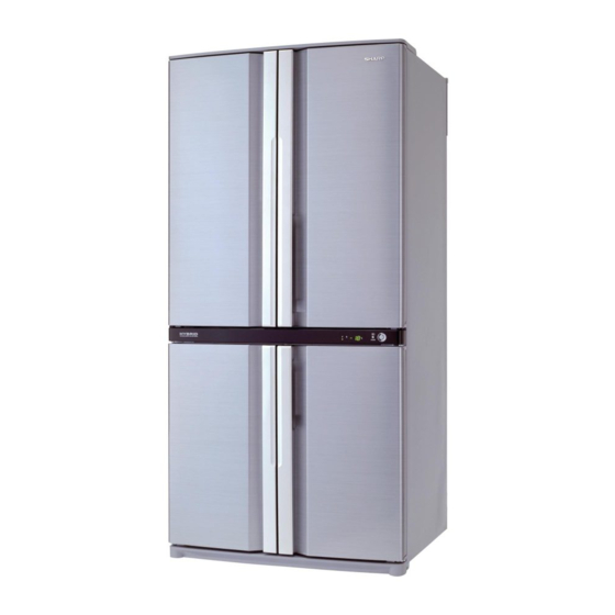
Page 6: Chapter 4. Designation Ofvarious Parts External Description
SJF800SPSL CHAPTER 4. SJF800SPSL DESIGNATION OFVARIOUS PARTS Service Manual [1] EXTERNAL DESCRIPTION The names in parenthesis “[ ]” are the denominations used in the REPLACEMENT PARTS LIST. 12 14 1. Door pocket [Door pocket ass'y] 2. Refrigerator shelf [R-shelf ass'y] 3. -
Page 7: Constructions
SJF800SPSL [2] CONSTRUCTIONS mark : cold air flow PWB-s ass'y Ionizer-K R-thermistor R fan motor Control panel Damper ass'y LCD PWB s ass'y Reed sw F-thermistor F-fan motor Fuse ass'y Evaporator Def-thermistor Defrost heater Sub condenser C fan motor Compressor Protector Starting relay Foot cover... -
Page 8: Chapter 5. Dimentions
SJF800SPSL CHAPTER 5. SJF800SPSL DIMENTIONS Service Manual [1] OUTER DIMENTIONS AND CLEARANCE 1. SJ-F750SP 1500 2. SJ-F800SP 1500 5 – 1... -
Page 9: Inner Dimentions
SJF800SPSL [2] INNER DIMENTIONS The dimensions between shelves can be changed by setting the shelves on the other rails. 1. SJ-F750SP 136.5 136.5 136.5 136.5 136.5 125.5 125.5 2. SJ-F800SP 136.5 136.5 136.5 136.5 136.5 136.5 125.5 125.5 5 – 2... -
Page 10: Chapter 6. List Of Electorical Parts
SJF800SPSL CHAPTER 6. SJF800SPSL LIST OF ELECTORICAL PARTS Service Manual ITEMS TYPE NAME RATING SPECIFICATIONS R Thermistor — DC 5V R0 = 6.4 kΩ, B(0) = 3811 F Thermistor — DC 5V R0 = 6.4 kΩ, B(0) = 3811 Defrost Themistor —... -
Page 11: Chapter 7. Wiring Diagram
SJF800SPSL CHAPTER 7. SJF800SPSL WIRING DIAGRAM Service Manual [1] WIRING DIAGRAM Be sure to replace the electrical parts with specified ones for maintaining the safety and performance of the set. Compressor Protector Starting relay Defrost Heater Light Running capacitor R-door heater Fuse Fuse2 Relay1... -
Page 12: Electric Accessories Layout
SJF800SPSL [2] ELECTRIC ACCESSORIES LAYOUT 7 – 2... -
Page 13: Chapter 8. Failure Diagnosis
SJF800SPSL CHAPTER 8. SJF800SPSL FAILURE DIAGNOSIS Service Manual [1] OUTLINE OF CONTROL 1. ON/OFF Control of Compressor • ON/OFF of the compressor will be controlled depend on the temperature detected by the R-thermistor and F-thermistor. (Normal cooling control) • In case the surrounding temperature is high at the power supply input, the compressor will be ON at once and the normal cooling control will start after several hours. -
Page 14: Diagnosis Method Of Failure Around Pwb
SJF800SPSL [4] DIAGNOSIS METHOD OF FAILURE AROUND PWB First of all, check by using the self-diagnosis. In case that the power supply doesn't enter, check by the following procedure. 1. Disconnect power supply and check the following point. • Is there any failure portion in inserting connectors? 2. -
Page 15: Conversion Table Between Temperature And Resistance Value
SJF800SPSL [5] CONVERSION TABLE BETWEEN TEMPERATURE AND RESISTANCE VALUE 1. R-thermistor Temperature Resistance Value Temperature Resistance Value Temperature Resistance Value (°C) (KΩ) (°C) (KΩ) (°C) (KΩ) 26.1 10.3 4.52 24.54 9.75 23.08 9.24 21.72 8.76 3.91 20.46 3.73 19.27 7.87 3.56 18.16 7.47... -
Page 16: Circuit Diagram Of Main Pwb
SJF800SPSL [6] CIRCUIT DIAGRAM OF MAIN PWB 8 – 4... -
Page 17: Circuit Diagram Of Lcd Pwb
SJF800SPSL [7] CIRCUIT DIAGRAM OF LCD PWB 8 – 5... -
Page 18: Chapter 9. Self-Diagnosis Mode
SJF800SPSL CHAPTER 9. SJF800SPSL SELF-DIAGNOSIS MODE Service Manual 1. Entering method of the mode 1) Press the [Select] button on the LCD panel over 5 seconds at the opening condition of the SELECT BUTTON freezer and refrigerating room doors. 2) With a beep sound of buzzer, the self-diagnosis mode is entered. When the self-diagnosis mode is not entered by the above operation, defect of Reed SW system can be considered. - Page 19 SJF800SPSL Status Buzzer Content Correspon- Display dence method No defects None - - - - →[1] F-thermistor system defect EE 01 R-thermistor system defect EE 02 →[2] Defect of each thermistor, short circuit/wire breakage of ther- DEF-thermistor system defect EE 03 →[3] mistor wiring and defect of main PWB Outside temperature-thermistor...
- Page 20 SJF800SPSL Correspondence method [ 2 ] [ 1 ] EE 02 / EH 62 / EH 77 EE 01 / EH 61 / EH 76 (F-thermistor system diagnosis) (R-thermistor system diagnosis) Power OFF Power OFF Remove 4P connector (flat) from Remove 6P connector from R E.V.
- Page 21 SJF800SPSL [ 3 ] [ 5 ] EE 03 / EH 63 EE 07 (Defrosting diagnosis) (DEF-thermistor system diagnosis) Turn power OFF. Reopen door and re-energize. (Buzzer beeps continuously) Power OFF Forced defrosting (Measurement is impossible when DEF-thermistor is set at 10°C or higher because defrosting ends immediately) After approx.
- Page 22 SJF800SPSL [ 6 ] [ 7 ] [ 8 ] EE 08 / EH 66 EE 09 / EH 67 EE 10 / EH 68 (F fan motor system diagnosis) (C fan motor system diagnosis) (R fan motor system diagnosis) Turn OFF and ON power.
- Page 23 SJF800SPSL [ 10 ] [ 9 ] EE 11 EE 12 (LCD system diagnosis) (Ionizer system diagnosis) of CN4 on the main PWB CN6 on the main PWB is positively are positively engaged? engaged? of 6P connector on R 5P connector on control panel is louver Assy are positively engaged? positively engaged? Insert connector.
-
Page 24: Chapter 10. Mode For Display
SJF800SPSL CHAPTER 10. SJF800SPSL MODE FOR DISPLAY Service Manual BUTTON SELECT EXPRESS 1. Entering method of the mode Within 2 minutes after main power input, press the [ ] button over 3 seconds at the opening condition of the refrigerating room door. NOTE: This cannot be made at the ON condition of CHILD LOCK. -
Page 25: Chapter 11. Disassembling/Assembling
SJF800SPSL CHAPTER 11. SJF800SPSL DISASSEMBLING/ASSEMBLING PROCEDURES Service Manual CAUTION: DISCONNECT THE UNIT FROM THE POWER SUPPLY BEFORE ANY REPAIRING. [1] REFRIGERATOR COMPARTMENT Parents parts name Included electrical parts Plasmacluster unit, Lr led pwb ass'y, Top led pwb ass'y, Pci pwb ass'y, R-louver ass'y Lr led harness, Pci indicator harness, R-thermistor R control box ass'y... - Page 26 SJF800SPSL 2. Assembling procedures of R CONTROL BOX ASS’Y. A-sealer ag4 A-sealer rc-c R air guider a Deodorizer A-sealer rc-g A-sealer rc-a R-C box cover R fan motor A-sealer rc-f R air guider b Lead r-c box Damper ass'y A-sealer rc-d 1.
- Page 27 SJF800SPSL 4. Insert R fan motor and damper ass’y to R air guider b, and Stick A-sealer rc-f to R air guider b. View from A R air guider b A-sealer rc-f R fan motor R air guider b Damper ass’y View from A 5.
- Page 28 SJF800SPSL 3. Assembling procedures of R-louver ass’y. R-louver insu A- sealer r-lv a Plasmacluster unit A-sealer r-lv b Al sheet l-guide R lamp cover t LIght guide Lr led harness Pci pwb ass’y Top led pwb ass’y Lr led pwb ass’y Led holder Pci indicator harness R thermistor...
- Page 29 SJF800SPSL 6. Fix Al panel to R-louver. 7. Fix 4) ass'y on the R-louver with tapping screw. 8. Connect Lr led harness to Lr led pwb ass'y and Top led pwb ass'y. 9. Fix 8) ass'y on R-louver. 10.Connect Pci indicator harness to plasmacluster unit. 11.
- Page 30 SJF800SPSL 16.Fix each harness by buffalo tape to R-louver. Pass the harness through the hole. Pass the harness through the hole. Buffalo tape Tapping R-louver Tapping R-thermistor 30 x 40 screw screw Lr led harness Hook Fix R-thermistor with hooks. Lr led harness Buffalo tape Buffalo tape...
-
Page 31: Freezer Compartment
SJF800SPSL [2] FREEZER COMPARTMENT Parents parts name Included electrical parts Ev cover ass'y F/df-thermistor, F fan motor Evaporator ass'y Fuse ass'y Def-heater ass'y Defrost heater 1. Disassembling procedures 4. Remove the f return cover. 5. Remove the fan louver. 1. Remove the accessories(shelves, case, etc.). 2. - Page 32 SJF800SPSL 2. Assembling procedures of C PARTITION FFB ASS’Y. V-partition lfb Sealer d V-partition rfb Sealer c Sealer e 1. Stick Sealer c to V-Partition lfb. V-PARTITION LFB SEALER C 2. Fix V-partition lfb and V-Partition rfb with the tapping screw. V-PARTITION LFB V-PARTITION RFB TAPPING SCREW...
- Page 33 SJF800SPSL 3. Stick Sealer d to the back side. Stick Sealer e to the bottom side. SEALER D SEALER E 3. Assembling procedures of E.V. COVER ASS’Y. Sealer fm EV-cover insu E.V. PE-AL sheet F/df-thermistor EV-cover sealer EV cover EV-cov. sealer c EV-c sealer l EV-cov.
- Page 34 SJF800SPSL 1. Assembly F fan motor Sticking of sealer to F fan motor. ii) Insert F fan motor to E.V cover .Then fix with tapping screw. Tappig screw 2. Sticking of sealers and PE-AL sheet to E.V cover. 3. Insert F/df-thermistor ( wire color : Blue) to E.V cover. 4.
- Page 35 SJF800SPSL 4. Banding the connectors 1. It is necessary to bind the connector joint of the Defrost heater and fuse ass’y in the band. Only the lower side Attach to each inside face. (reverce of lock) lock lock 3P-connector 2P-connector (Defrost heater) (Fuse ass'y) 11 –...
-
Page 36: How To Remove The Control Base
SJF800SPSL [3] HOW TO REMOVE THE CONTROL BASE 1. Insert the sharp tool into gap between control panel and control base, and then push it for take out the claw from control base. CLAW Control panel INSERT SHARP IN THIS POSITION 2. -
Page 37: Defrost Heater
SJF800SPSL [4] DEFROST HEATER 2. Replacement of Def. heater. 1. Remove the center screw of Heater support to take it off from the 1. Taking-out Evaporator food liner. 1. Take-out C Partition ffb ass’y. 2. Take-out Fan louver. 3. Take-out E.V cover ass’y. Heater support E vaporator F ood liner convex part... - Page 38 SJF800SPSL 4. Replace Def. heater with new one. 3. Installing of Evaporator 1. Install Evaporator as shown in 1-3 in the reverse order of 1-4. 2. Correct the deformed fin. NOTE: 1.When installing Evaporator, take care not to deform signifi- cantly and break the pipes.
-
Page 39: When Left And Right Doors Are Not On The Same Level
SJF800SPSL [5] WHEN LEFT AND RIGHT DOORS ARE NOT ON THE SAME LEVEL 1. Cause The floor is not flat and refrigerator is slanting. 2. Adjustment 1. Unscrew 4 screws on the bottom of the cabinet,and remove the foot cover. Adjustable foot Foot cover 2. -
Page 40: Chapter 12. Cooling Unit
SJF800SPSL CHAPTER 12. SJF800SPSL COOLING UNIT Service Manual [1] COOLING UNIT 12 – 1... -
Page 41: Location
SJF800SPSL [2] LOCATION 1. Location 1 Capillary tube -HC-S -HC-L Eva. pan P-Connector pipe ass’y 2. Location 2 From DC P-Connector From E pan pipe s ass to Sub condernser From Bottom condenser From CHRG-PIPE-HC-S to BTM condenser to Hot pipe to Dryer From Suction pipe ass to S Connector... - Page 42 SJF800SPSL 12 – 3...
-
Page 43: Parts Guide
SJF800SPSL PartsGuide PARTS GUIDE Refrigerator-freezer MODELS SJ-F750SP-SL/BK SJ-F800SP-SL/BK CONTENTS SJ-F750SP DOOR SJ-F800SP DOOR SJ-F750SP CABINET1 SJ-F800SP CABINET1 SJ-F750SP CABINET2 SJ-F800SP CABINET2 SJ-F750SP CYCLE SJ-F800SP CYCLE SJ-F750SP OTHERS [10] SJ-F800SP OTHERS INDEX This document has been published to be used for after sales service only. -
Page 44: Sj-F750Sp Door
SJF800SPSL [1] SJ-F750SP DOOR 3-21-1 3-21-4 3-47 3-22 3-28 3-55 3-31-1 3-46 3-47 3-57 3-31-4 3-28 3-56 3-51 3-46 3-58 3-32 3-31 3-53 3-52 3-54 3-26 3-40 3-26 3-47 3-54 3-21 3-21-5 3-52 3-53 3-21-2 3-21-3 3-58 5-3-1 3-51 3-56 3-57 3-31-3 3-31-5... - Page 45 SJF800SPSL PRICE PART PARTS CODE DESCRIPTION RANK MARK RANK [1] SJ-F750SP DOOR F-door l ass'y [SL] FDORFC066CBKZ F-door l ass'y [BK] FDORFC073CBKZ 3-1-1 F-door stopper r LSTPMA008CBM0 3-1-2 Fd-stp spring l LSTPPA146CBFA 3-1-3 Nylon bearing 3s NBRGPA022CBFA F door packing FPACGA431CBYA Fd-handle JHNDPA296CBPZ...
-
Page 46: Sj-F750Sp Cabinet1
SJF800SPSL [2] SJ-F750SP CABINET1 5-11 5-11-3 2-115 5-11-1 5-11-4 5-11-5 2-116 5-11-2 2-117 5-12 2-36 5-13 5-12-3 5-12-1 5-13-2 5-13-3 5-12-4 5-13-1 5-12-2 5-17 90-33 2-93 5-16 2-119 5-14 2-112 2-111 2-105 2-93 2-49 5-15 2-114 5-18 2-113 2-106 2-107 3-45 2-145 2-143... - Page 47 SJF800SPSL PRICE PART PARTS CODE DESCRIPTION RANK MARK RANK [2] SJ-F750SP CABINET1 Hinge cover [SL] PCOVPA398CBFA Hinge cover [BK] PCOVPA398CBFF Hinge support-t [SL] LPLTPA416CBTA Hinge support-t [BK] LPLTPA416CBTB Carrying bar JHNDMA025CBPZ Leg holder-ls k FLEGPA127CBKZ 2-7-1 Adjustable leg ass'y FAJS-A028CBKZ 2-7-2 Leg holder-lk FLEGPA123CBYZ...
-
Page 48: Sj-F750Sp Cabinet2
SJF800SPSL [3] SJ-F750SP CABINET2 2-58 2-56 1-45 2-167 1-65 1-62 1-64 2-29 1-63 2-161 2-162 2-166 1-64 1-61 2-163 1-61 2-37 2-55 2-25 2-125 2-37 2-26 2-149 2-74 2-34 2-38 2-165 2-27 2-72 1-27 2-164 2-160 2-39 1-26 2-97 2-148 1-10 1-55 2-132... - Page 49 SJF800SPSL PRICE PART PARTS CODE DESCRIPTION RANK MARK RANK [3] SJ-F750SP CABINET2 F/df-thermistor RH-HXA108CBZZ R-thermistor RH-HXA123CBZZ Damper ass'y DTHM-A031CBKZ F fan motor RMOTRA096CBZZ 1-10 Reed sw ass'y FSW-LA001CBKZ 1-17 Fuse ass'y FFS-TA087CBKZ 1-21 Defrost heater FHETBA193CBZZ 1-26 Lead r-c box QCNW-B146CBZZ 1-27 R fan motor...
-
Page 50: Sj-F750Sp Cycle
SJF800SPSL [4] SJ-F750SP CYCLE 2-24 1-50 2-51 2-123 6-17 2-78 6-42 4-14 6-32 2-87 2-152 2-151 1-41 2-126 2-99 6-27 6-41 6-28 5-41 2-153 1-31 1-22 2-136 4-10 2-88 1-23 6-36 4-17 6-18 6-11 1-11 2-87 6-40 2-77 2-80 4-15 6-21 6-10 6-27... -
Page 51: Sj-F750Sp Others
SJF800SPSL PRICE PART PARTS CODE DESCRIPTION RANK MARK RANK [4] SJ-F750SP CYCLE 2-77 T-box holder LHLD-A359CBFA 2-78 Dryer support LPLTMA399CBP0 2-80 Terminal box PBOX-A148CBFA 2-87 Fastening band a LBND-A018CBE0 2-88 LBND-A019CBE0 Nylon band 2-99 PPIPPA126CBFZ Drain pipe s 2-123 GCOV-A283CBPZ Comp.cover 2-126 Cfm frame... -
Page 52: Sj-F800Sp Door
SJF800SPSL [6] SJ-F800SP DOOR 3-21-1 3-21-4 3-47 3-22 3-28 3-55 3-31-1 3-46 3-47 3-57 3-31-4 3-28 3-56 3-51 3-46 3-58 3-32 3-31 3-53 3-52 3-54 3-26 3-40 3-26 3-47 3-54 3-21 3-21-5 3-52 3-53 3-21-2 3-21-3 3-58 5-3-1 3-51 3-56 3-57 3-31-3 3-31-5... - Page 53 SJF800SPSL PRICE PART PARTS CODE DESCRIPTION RANK MARK RANK [6] SJ-F800SP DOOR F-door l ass'y [SL] FDORFC066CBKZ F-door l ass'y [BK] FDORFC073CBKZ 3-1-1 F-door stopper r LSTPMA008CBM0 3-1-2 Fd-stp spring l LSTPPA146CBFA 3-1-3 Nylon bearing 3s NBRGPA022CBFA F door packing FPACGA431CBYA Fd-handle JHNDPA296CBPZ...
-
Page 54: Sj-F800Sp Cabinet1
SJF800SPSL [7] SJ-F800SP CABINET1 5-11 5-11-3 2-115 5-11-1 5-11-4 5-11-5 2-116 5-11-2 2-117 5-12 2-36 5-13 5-12-3 5-12-1 5-13-2 5-13-3 5-12-4 5-13-1 5-12-2 5-17 90-33 2-93 5-16 2-119 5-14 2-112 2-111 2-105 2-93 2-49 5-15 2-114 5-18 2-113 2-106 2-107 3-45 2-145 2-143... - Page 55 SJF800SPSL PRICE PART PARTS CODE DESCRIPTION RANK MARK RANK [7] SJ-F800SP CABINET1 Hinge cover [SL] PCOVPA398CBFA Hinge cover [BK] PCOVPA398CBFF Hinge support-t [SL] LPLTPA416CBTA Hinge support-t [BK] LPLTPA416CBTB Carrying bar JHNDMA025CBPZ Leg holder-ls k FLEGPA127CBKZ 2-7-1 Adjustable leg ass'y FAJS-A028CBKZ 2-7-2 Leg holder-lk FLEGPA123CBYZ...
-
Page 56: Sj-F800Sp Cabinet2
SJF800SPSL [8] SJ-F800SP CABINET2 2-58 2-56 1-45 2-167 1-65 1-62 1-64 2-29 1-63 2-161 2-162 2-166 1-64 1-61 2-163 1-61 2-37 2-55 2-25 2-125 2-37 2-26 2-149 2-74 2-34 2-38 2-165 2-27 2-72 1-27 2-164 2-160 2-39 1-26 2-97 2-148 1-10 1-55 2-132... - Page 57 SJF800SPSL PRICE PART PARTS CODE DESCRIPTION RANK MARK RANK [8] SJ-F800SP CABINET2 F/df-thermistor RH-HXA108CBZZ R-thermistor RH-HXA123CBZZ Damper ass'y DTHM-A031CBKZ F fan motor RMOTRA096CBZZ 1-10 Reed sw ass'y FSW-LA001CBKZ 1-17 Fuse ass'y FFS-TA087CBKZ 1-21 Defrost heater FHETBA193CBZZ 1-26 Lead r-c box QCNW-B146CBZZ 1-27 R fan motor...
-
Page 58: Sj-F800Sp Cycle
SJF800SPSL [9] SJ-F800SP CYCLE 2-24 1-50 2-51 2-123 6-17 2-78 6-42 4-14 6-32 2-87 2-152 2-151 1-41 2-126 2-99 6-27 6-41 6-28 5-41 2-153 1-31 1-22 2-136 4-10 2-88 1-23 6-36 4-17 6-18 6-11 1-11 2-87 6-40 2-77 2-80 4-15 6-21 6-10 6-27... -
Page 59: Sj-F800Sp Others
SJF800SPSL PRICE PART PARTS CODE DESCRIPTION RANK MARK RANK [9] SJ-F800SP CYCLE 2-77 T-box holder LHLD-A359CBFA 2-78 Dryer support LPLTMA399CBP0 2-80 Terminal box PBOX-A148CBFA 2-87 Fastening band a LBND-A018CBE0 2-88 LBND-A019CBE0 Nylon band 2-99 PPIPPA126CBFZ Drain pipe s 2-123 GCOV-A283CBPZ Comp.cover 2-126 Cfm frame... -
Page 60: Index
SJF800SPSL INDEX PRICE PART PRICE PART PARTS CODE PARTS CODE RANK MARK RANK RANK MARK RANK FPOK-A272CBKZ 1-5-3 [ C ] " 6-5-3 CKITTA131AKKZ 3-1-45 FPOK-A273CBKZ 1-5-4 " 8-1-45 " 6-5-4 CPADBA076CBKZ 5-90-6 FPOK-A274CBKZ 6-5-7 " 10-90-6 CPADBA077CBKZ 5-90-7 FPWB-A615CBKZ 3-1-55 "... - Page 61 SJF800SPSL PRICE PART PRICE PART PARTS CODE PARTS CODE RANK MARK RANK RANK MARK RANK " 6-3-53 " 8-2-67 HDECQA599CBTB 1-3-53 LPLTPA559CBPZ 1-3-57 " 6-3-53 " 6-3-57 HDECQA600CBTA 1-3-54 LPLTPA560CBPZ 1-3-58 " 6-3-54 " 6-3-58 HDECQA600CBTB 1-3-54 LPLTPA561CBFA 3-2-163 " 6-3-54 "...
- Page 62 SJF800SPSL PRICE PART PRICE PART PARTS CODE PARTS CODE RANK MARK RANK RANK MARK RANK PCOV-A435CBFA 3-2-25 PSEL-C662CBZZ 4-2-153 PCOV-A436CBFA 3-2-26 " 9-2-153 PCOVPA271CBEZ 4-6-21 PSEL-C669CBZZ 3-2-148 " 9-6-21 " 8-2-148 PCOVPA398CBFA 2-2-3 PSEL-E009CBZZ 8-2-58 " 7-2-3 PSEL-E015CBZZ 3-2-58 PCOVPA398CBFF 2-2-3 PSEL-E035CBZZ 6-3-46...
- Page 63 SJF800SPSL PRICE PART PARTS CODE RANK MARK RANK SSAKHA011CBZZ 5-90-43 [ T ] TINS-A743CBRZ 5-90-19 " 10-90-19 TINS-A946CBRZ 5-90-1 " 10-90-1 TINSEA046CBRZ 5-90-8 " 10-90-8 TLAB-A637CBR0 5-90-13 " 10-90-13 TLAB-A638CBR0 5-90-13 " 10-90-13 TLAB-A639CBR0 5-90-13 " 10-90-13 TLAB-A640CBR0 5-90-13 " 10-90-13 TLAB-A641CBR0 5-90-13...
- Page 64 COPYRIGHT © 2009 BY SHARP CORPORATION ALL RIGHTS RESERVED. © COPYRIGHT XXXX BYSHARP CORPORATION No part of this publication may be reproduced, stored ALL RIGHTS RESERVED. in retrieval systems, or transmitted in any form or by any means, electronic, mechanical, photocopying, re-...