
Related Manuals for Galaxy Audio ANY SPOT


Summary of Contents for Galaxy Audio ANY SPOT
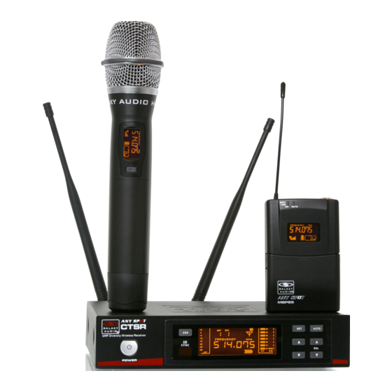
- Page 1 U H F USER’S MANUAL ® WIRELESS MICROPHONE SYSTEM UHF Diversity Wireless Receiver...
-
Page 2: Table Of Contents
Contents Contents Introduction....................1 CTS System Components................2 Functions of the CTSR Receiver..............3-4 Mounting & Connecting the Receiver.............5 System Setup....................6-8 HH85 Handheld Transmitter................9 MBP85 Body Pack..................10-11 Main Functions Description of Transmitters..........12 Handheld and Body Pack Transmitter.............13-14 Troubleshooting..................15 Specifications.....................16 DTV Frequency Ranges & FCC Consumer Alert...........17... -
Page 3: Introduction
Introduction Introduction Thank you for choosing the Galaxy Audio CTS Wireless Microphone System. You have joined hundreds of thousands of other satisfied Galaxy customers. Since 1977 Galaxy Audio’s professional experience in design and manufacturing ensure our products quality, performance and reliability. -
Page 4: Cts System Components
CTS System Components CTS System Components System Overview The CTS system is specifically designed for a variety of performance art. The CTS system has 18 different groups, and each group consists of 14 compatible receiving channels. The CTS system is capable of searching for vacant channels automatically. -
Page 5: Functions Of The Ctsr Receiver
Functions of the CTSR Receiver Functions of the CTSR Receiver CTSR Receiver Features Front Panel CTSR UHF Diversity Wireless Receiver UHF Diversity Wireless Receiver System Menu up button Power Switch. With red light indicator, press it one second to turn it on or off. -
Page 6: Functions Of The Ctsr Receiver
Functions of the CTSR Receiver Functions of the CTSR Receiver Rear Panel DC power socket Balanced audio output socket: XLR Unbalanced audio output socket: 1/4" Antenna Socket Receiver LCD Functions Function Display IR Syncing Indicator Audio Level Current Group Number Current Channel Number Current Frequency Mute, it will disappear when the mic is on... -
Page 7: Mounting & Connecting The Receiver
Mounting & Connecting the Receiver Mounting & Connecting the Receiver Mounting & Connecting the Receiver MREWD Single/Dual Rack Kit DC power adapter Balanced output cable 1/4 inch output cable BNC CONNECTOR & CABLE: For front mounting antenna to rack ears. Part# AS-EXT50/BNC (optional) UHF Diversity Wireless Receiver Rack-Mounting Two CTS Receivers... -
Page 8: System Setup
System Setup System Setup 1. IR SYNC Setting Press the button, the icon will flash for 10 seconds. During the 10 seconds aim the transmitter IR window at the receiver IR window and the transmitter will sync to the receiver frequency. When the sync is complete the icon will disappear and the display will return to its normal state. - Page 9 System Setup System Setup 2. Selecting Frequency Press button. The GP flashes to indicate the group can be chosen by pressing the button, to confirm press the button. It will return back to the original state without any operation within 5 seconds. Press to confirm the group selection, the CH flashes to indicate the channel can be chosen, press the...
-
Page 10: System Setup
System Setup System Setup 4. Automatically Search for Vacant Channel Press , the icon will start to flash then available channels within the selected group will be shown on the LCD display. For example, the LCD display shows 15, that means there are 15 vacant channels available. Then Press the button to select an appropriate channel. -
Page 11: Hh85 Handheld Transmitter
HH85 Handheld Transmitter HH85 Handheld Transmitter Functions: Microphone Grille LCD Display Power and Mute switch: hold for three seconds to power on or off. Click once to mute or unmute output signal System setting button. System selection button. Battery holder. IR port: Receives the IR signal to SYNC to the CTSR receiver. -
Page 12: Mbp85 Body Pack
MBP85 Body Pack Transmitter MBP85 Body Pack Transmitter Functions: Mini XLR input socket Power/Mute switch: Press it and hold for three seconds to power on or off. Click once to mute or unmute output signal Antenna Low battery indicator Mute indicator LCD Display IR window: Receives the IR signal to SYNC to the CTSR receiver... - Page 13 Output impedance: <2K Ω S/N Ratio: <38dB LV-U3BK Clip-on Microphone Polar Patten: Unidirectional Sensitivity: -64dB ± 2.2dB Frequency Response: 100Hz-20KHz Output impedance:2K Ω S/N Ratio: >44dB LV-U3BK This is just a sample of the many headset options available from Galaxy Audio. Guitar Cable...
-
Page 14: Main Functions Description Of Transmitters
Main Functions Description of Transmitters Main Functions Description of Transmitters Function Display Transmitter Output Power Battery Status Current Frequency Mute Symbol Transmitter Output Level Current Group Number Current Channel Number Function Locked Indicator... -
Page 15: Handheld And Body Pack Transmitter
Handheld and Body Pack Transmitter Handheld and Body Pack Transmitter Current Frequency Checking: Press button to show the current frequency, press to return. If no operation was performed within 5 seconds, the display will return back to normal display automatically. Transmitter gain adjust: Press symbol flashing, press the... -
Page 16: Handheld And Body Pack Transmitter
Handheld and Body Pack Transmitter Handheld and Body Pack Transmitter Mute setting: On the body pack, press once, the transmitter will be muted right away and the icon displayed, press one more time to unmute it. For the handheld, repeat the same steps using the button. -
Page 17: Troubleshooting
Troubleshooting Troubleshooting Tips for Improving System Performance Maintain a line of sight between transmitter and antenna. Avoid placing the receiver near metal surfaces or any digital equipment (CD players, computers, etc). Keep the receiver away from the wall and over 1m to the ground. Cellular telephones, two-way radios and other RF transmitters can interfere with the transmitting frequencies, maintain a distance from interfering equipment. -
Page 18: Specifications
Power Requirements: 2 “AA” size alkaline or rechargeable batteries Battery Life: About 8 Hrs dependent on power setting Dimensions: 3.85" x 2.51" x 0.90" (98 x 64 x 23 mm)(HxWxD) Weight: 3.17 oz (90 g) GALAXY AUDIO Frequency Chart Frequency Page http://www.galaxyaudio.com/assets/uploads/media/CTS_Freqs.jpg http://www.galaxyaudio.com/support/schematics-and-frequency-charts... -
Page 19: Dtv Frequency Ranges & Fcc Consumer Alert
DTV Frequency Ranges & FCC Consumer Alert DTV Frequency Ranges & FCC Consumer Alert The frequencies of the Galaxy UHF Wireless Systems are on DTV RF Frequency frequencies that are used by Digital Television stations. Channel Range 470-476 To be assured of the best performance, you should determine on 476-482 482-488 what RF channels the DTV stations in your area are broadcasting,... - Page 20 WARRANTY Information can be viewed online at http://www.galaxyaudio.com/support/warranty www.galaxyaudio.com/support/warranty USER’S MANUAL Specifications in this manual are subject to change without notice. For the most up to date manual and information visit www.galaxyaudio.com. 1-800-369-7768 www.galaxyaudio.com © Copyright Galaxy Audio 2017 V20170501...