
Related Manuals for Canon J1

Summary of Contents for Canon J1
- Page 1 Staple Finisher-J1 / Booklet Finisher-J1 Service Manual Rev0 Product Outline Technology Periodic Servicing Parts Replacement and Cleaning Procedure Adjustment Installation Appendix...
- Page 2 Canon will release technical information as the need arises. In the may not be copied, reproduced or translated into another language, in whole or in part, event of major changes in the contents of this manual over a long or short period, Canon without the consent of Canon Inc.
- Page 3 Explanation of Symbols The following rules apply throughout this Service Manual: The following symbols are used throughout this Service Manual. 1. Each chapter contains sections explaining the purpose of specific functions and the relationship between electrical and mechanical systems with reference to the timing of Symbols Explanation Symbols...
- Page 4 Blank Page...
-
Page 5: Table Of Contents
Contents Booklet Finisher ----------------------------------------------------------------------------- 2-8 Paper Delivery Path --------------------------------------------------------------- 2-9 Straight Ejection ----------------------------------------------------------------------------- 2-9 Processing Tray Path ---------------------------------------------------------------------2-10 Buffer/Processing Tray Path ------------------------------------------------------------2-10 Paper Delivery Path (Saddle Stitcher Unit) ----------------------------------------- 2-11 Safety Precautions Stack Tray Unit -------------------------------------------------------------- 2-12 Notes Before it Works Serving ---------------------------------------------0-9 Tray Operation ---------------------------------------------------------------------2-12 Points to Note at Cleaning --------------------------------------------------0-9 Shutter Operation -----------------------------------------------------------------2-13... - Page 6 Staple Operation ------------------------------------------------------------ 2-30 List of Consumable Parts and Cleaning Parts ------------------------------ 4-5 Overview ----------------------------------------------------------------------------2-30 List of Sensors ---------------------------------------------------------------------- 4-6 Stapler Unit -------------------------------------------------------------------------2-30 Staple Finisher Unit ------------------------------------------------------------------------ 4-6 Saddle Finisher Unit ----------------------------------------------------------------------- 4-7 Stapler ---------------------------------------------------------------------------------------2-30 List of Switchs ---------------------------------------------------------------------- 4-8 Shifting the Stapler Unit ------------------------------------------------------------------2-31 Stapling Operation-------------------------------------------------------------------------2-33 Staple Finisher Unit ------------------------------------------------------------------------ 4-8...
- Page 7 Adjusting the Processing Tray Return Speed. ----------------------------- 5-11 Special Tools --------------------------------------------------------------------------- ii Initializing the RAM on Finisher -----------------------------------------------5-12 General Circuit Diagram ------------------------------------------------------- iii Adjusting the Bias Line of Saddle Delivery Paper -----------------------5-12 Staple Finisher-J1 --------------------------------------------------------------------iii Overview -------------------------------------------------------------------------------------5-12 Booklet Finisher-J1 ------------------------------------------------------------------- v Adjustment ----------------------------------------------------------------------------------5-12...
-
Page 8: Safety Precautions
Safety Precautions ■ Notes Before it Works Serving ■ Points to Note at Cleaning... -
Page 9: Notes Before It Works Serving
Notes Before it Works Serving CAUTION: At servicing, be sure to turn off the power source according to the specified steps and disconnect the power plug. CAUTION: Do not turn off the power switch when downloading is under way. Turning off the main power switch while downloading is under way can disable the machine. - Page 10 Product Outline ■ Features ■ Specifications ■ Names of Parts ■ Optional Construction Product Outline...
-
Page 11: Product Outline Features
Product Outline > Features Features Office environment improvement • Operation sound reduction Productivity improvement • 51ppm→55ppm Service improvement • Downloading from host machine • Adjustment of finisher in the service mode of host machine Product Outline > Features... -
Page 12: Specifications
Product Outline > Specifications Specifications Item Specifications Remarks Stapling capacity Small size: Equivalent of 80g/ Plain paper (52 to 81.4 g/m2): 50 sheets m2 paper. Item Specifications Remarks Plain paper (81.4 to 105 g/m2):30 sheets Stacking method Tray 1 and 2: Independently move up and down Thick paper (105 to 220 g/m2): 2 sheets Stacking Face up, Face down... -
Page 13: Saddle Stitcher Unit
Product Outline > Specifications > Saddle Stitcher Unit Saddle Stitcher Unit Stapling Positions Front 1-point stapling (30deg.) Front 1-point stapling (45deg.) Item Specifications Remarks A4R, LGL and LTRR A3,A4,B4,B5, 279mm×432mm(11×17) ,LTR,EXEC,8K,16K Stapling method Vertically separated, round-clinch stapling at two positions in the middle Paper size A3, B4, A4R, 279mm x 432mm (11 x 17), LGL, LTRR/ 305mm x 457mm (12 x 18) - Page 14 Product Outline > Specifications > Saddle Stitcher Unit Staple position Folding position -/+2 mm 63 -/+2 mm 39.5 -/+2 mm 203 -/+2 mm 183 -/+2 mm 159.5 -/+2 mm Stack front edge LTRR 279mm x 432mm (11 x 17) 42 -/+2 mm 42 -/+2 mm -/+2 mm 162 -/+2 mm...
-
Page 15: External View
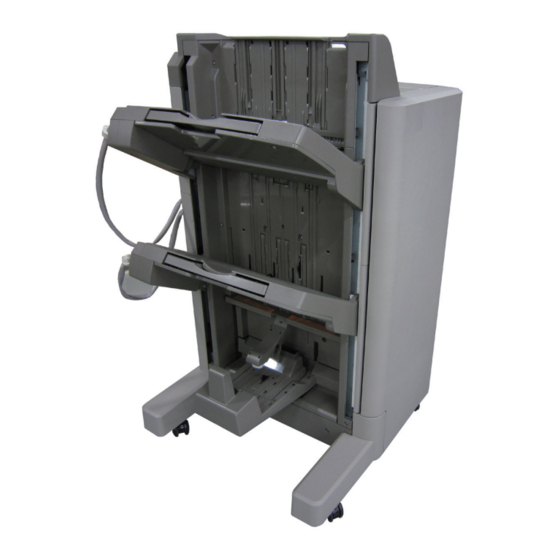
Product Outline > Names of Parts > External View > Saddle Finisher (Booklet Finisher) Names of Parts ■ Saddle Finisher (Booklet Finisher) Grate-shaped Left upper cover External View Upper cover upper guide Rear cover ■ Finisher (Staple Finisher) Front cover latch unit Tray 1 Upper cover... -
Page 16: Cross Section
Product Outline > Names of Parts > Cross Section > Saddle Unit Cross Section ■ Saddle Unit ■ Finisher Unit Saddle stitcher flapper Aligning plate 1st delivery roller Stack delivery Buffer roller Inlet roller 1 roller Inlet roller Shutter Inlet roller 2 Return roller No.1 flapper Delivery tray... -
Page 17: Optional Construction
Product Outline > Optional Construction Optional Construction The following optional machine can install to the finisher. [1] External 2, 2/3, 2/4 , 4 Hole Puncher-B2 Staple finisher Saddle finisher F-1-7 Product Outline > Optional Construction... -
Page 18: Technology
Technology ■ Basic Constitution ■ Controls ■ Feeding Unit ■ Processing Tray Unit ■ Stack Tray Unit ■ Saddle Stitcher Unit ■ Staple Operation ■ Detecting Jams ■ Power Supply ■ Work of Service Technology... -
Page 19: Component Configuration
Technology > Basic Constitution > Component Configuration > Saddle Finisher (Booklet Finisher) Basic Constitution ■ Saddle Finisher (Booklet Finisher) Component Configuration [Feed Unit] The components of this saddle finisher are organized into 4 major blocks and this finisher are organized into 3 major blocks; feed unit, processing unit, stack tray unit and saddle stitcher unit. -
Page 20: Overview Of The Electrical Circuitry
Technology > Basic Constitution > Overview of the Electrical Circuitry (Saddle Stitcher Unit) Overview of the Electrical Circuitry The finisher’s sequence of operation is controlled by the finisher controller PCB. The finisher controller PCB is a 16-bit microprocessor (CPU), and is used for communication with the host machine (serial) in addition to controlling the finisher’s sequence of operations. -
Page 21: Controls
Technology > Controls Controls Items Reference 1.Feeding Unit Overview Refer to page 2-5 Construction Refer to page 2-6 Delivery path Refer to page 2-9 2.Stacking Trey Tray operation Refer to page 2-12 Shutter operation Refer to page 2-13 3. Process Tray Overview Refer to page 2-14 Basic operation... -
Page 22: Feeding Unit
Technology > Feeding Unit > Overview > Booklet Finisher Feeding Unit ■ Booklet Finisher This product consists of the Finisher unit and the Saddle Stitcher unit. Overview The Finisher unit simply stacks sheets delivered from a host machine, offsets a stack job, or staples and delivers the sheets to the trays according to commands delivered from a host ■... -
Page 23: Construction Of The Control System
Technology > Feeding Unit > Construction of the Control System > Staple Finisher Construction of the Control System ■ Staple Finisher The copy sent from the host machine is delivered to the ejection tray or processing tray Normal delivery tray according to the ejection type. - Page 24 Finisher controller PCB Finisher controller PCB (1/2) M103 M102 M110 M109 M101 M104 M107 M105 M111 M108 F-2-8 Finisher controller PCB (2/2) F-2-7...
-
Page 25: Booklet Finisher
Technology > Feeding Unit > Construction of the Control System > Booklet Finisher ■ Booklet Finisher Finisher controller PCB (1/2) The copy sent from the host machine is delivered to the ejection tray, processing tray, or saddle stitcher according to the ejection type. Job offset or stapling is performed, according to the instruction from the host machine, for copy delivered to the staple tray. -
Page 26: Paper Delivery Path
Technology > Feeding Unit > Paper Delivery Path > Straight Ejection Paper Delivery Path Finisher controller PCB There are three ejection paths to tray 1 and 2 depending on the ejection processing. Furthermore, Booklet Finisher has ejection paths for Saddle Stitcher Unit. ■... -
Page 27: Processing Tray Path
Technology > Feeding Unit > Paper Delivery Path > Buffer/Processing Tray Path 2-10 ■ Processing Tray Path ■ Buffer/Processing Tray Path This is the copy ejection path when the equipment is set to sort for paper size other than A4, This is the copy ejection path when the equipment is set to sort for A4, B5, or LTR paper size. - Page 28 Technology > Feeding Unit > Paper Delivery Path > Paper Delivery Path (Saddle Stitcher Unit) 2-11 ■ Paper Delivery Path (Saddle Stitcher Unit) 3) The first delivery roller descends and works together with the stack delivery roller to deliver the 1st and 2nd paper toward the processing tray. A copy arriving in the finisher from the host machine is routed to the saddle stitcher by the At the same time,the stack in the processing tray is delivered toward the delivery tray by the saddle stitcher flapper.
-
Page 29: Stack Tray Unit
Technology > Stack Tray Unit > Tray Operation 2-12 Stack Tray Unit Rack Tray 1 paper surface sensor (PI111) Tray Operation Tray 1 switch (MSW103) This equipment has two delivery trays. The upper tray is called tray 1 and the lower tray is called tray 2. The upper and lower tray can move up and down independently. -
Page 30: Shutter Operation
Technology > Stack Tray Unit > Shutter Operation 2-13 Shutter Operation Paper surface sensor (PI114) Paper surface sensor flag When tray 1 passes the delivery section with paper already stacked, the stacked paper may get caught by the delivery section. Edge A shutter is provided at the delivery section to prevent this. -
Page 31: Processing Tray Unit
Technology > Processing Tray Unit > Basic Operation > Stack Delivery Operation 2-14 Processing Tray Unit ■ Stack Delivery Operation In order to improve stacking performance when ejecting copies delivered to the processing Outline tray, a rear end assist guide is used in addition to the stack ejection roller to support the rear end of the stack during stack ejection. - Page 32 Technology > Processing Tray Unit > Basic Operation > Stack Job Offset 2-15 ■ Stack Job Offset The stack is ejected each time three large size sheets*1 or five small size sheets*2 are offset on the processing tray. Job offset operation offsets paper stack to the front or rear when ejecting to sort the paper The swing motor turns and the swing guide descends.
-
Page 33: Staple Operation
Technology > Processing Tray Unit > Basic Operation > Staple Operation 2-16 ■ Staple Operation An example:4 sheets , 4 sets , A4 size ,(printing total :16 sheets) 1)From the 1 sheet to the 4 sheets, move it towards a board. This product is equipped with two Staplers. -
Page 34: Swing Height Detection Control
Technology > Processing Tray Unit > Basic Operation > Swing Height Detection Control 2-17 ■ Swing Height Detection Control 1. Overview Normally, the color-printed paper is ejected to the process tray with it rubbing against the paper loaded in the process tray, causing scratches on the printed image. To prevent this, the swing unit height is controlled. -
Page 35: Saddle Stitcher Unit
Technology > Saddle Stitcher Unit > Basic Operation (Saddle Stitcher Unit) > Aligning the Sheets 2-18 Saddle Stitcher Unit ■ Aligning the Sheets The alignment plates operate to put the sheets in order each time a sheet of paper is output Basic Operation (Saddle Stitcher Unit) to the vertical path assembly. - Page 36 Technology > Saddle Stitcher Unit > Basic Operation (Saddle Stitcher Unit) > Feeding the Stack 2-19 ■ Stitching ■ Feeding the Stack When all sheets have been output, the two stitchers stitch the stack. The stitchers are The unit folds the stitched stack of sheets, and then feeds it to the point of delivery. positioned so that they face the center of a stack.
-
Page 37: Controlling The Inlet Flappers
Technology > Saddle Stitcher Unit > Controlling the Inlet Flappers > Overview 2-20 ■ Folding/Delivering the Stack Controlling the Inlet Flappers The paper pushing plate pushes against the center of the stack to move it in the direction of ■ Overview the paper folding rollers. -
Page 38: A3/A3/ 305Mm X 457Mm (12 X 18)/ 279Mm X 432Mm (11 X 17) Paper Path (3 Sheets)
Technology > Saddle Stitcher Unit > Controlling the Inlet Flappers > B4/LGL Paper Path (3 sheets) 2-21 ■ A3/A3/ 305mm x 457mm (12 x 18)/ 279mm x 432mm (11 x 17) ■ B4/LGL Paper Path (3 sheets) Paper Path (3 sheets) Passage of paper No.1 paper sensor PI18... -
Page 39: A4R/Ltrr Paper Path (3 Sheets)
Technology > Saddle Stitcher Unit > Controlling the Movement of Sheets 2-22 ■ A4R/LTRR Paper Path (3 sheets) Controlling the Movement of Sheets When the leading edge of a sheet has moved past the inlet flapper, the intermediate feed roller and the crescent roller start to move the sheet forward. The intermediate feed roller is normally not in contact with the path bed. -
Page 40: Controlling The Aligning The Sheets
Technology > Saddle Stitcher Unit > Controlling the Aligning the Sheets 2-23 Controlling the Aligning the Sheets 2) The solenoid turn OFF when the paper butts against the paper positioning plate. The feed motor continues to rotate. The alignment motor (M5) drives the alignment plates each time a sheet is output, putting both left and right edges of the sheet in order. - Page 41 Technology > Saddle Stitcher Unit > Controlling the Aligning the Sheets 2-24 3) The alignment plates escape to points 10 mm from the edge of the stack. Alignment plate Alignment motor Alignment plate F-2-45 Stack 4) When the following stack arrives, steps 1 through 3 above are repeated. 5) The alignment plates butt against the stack once again, during which stitching takes place.
-
Page 42: Controlling The Phase Of The Crescent Roller
Technology > Saddle Stitcher Unit > Controlling the Phase of the Crescent Roller 2-25 Controlling the Phase of the Crescent Roller Alignment plates If alignment was executed with the crescent roller in contact with the stack of sheets, the resulting friction against the roller causes the stack to move inappropriately. To prevent this problem, the phase of the roller is identified and used to determine the timing of alignment. -
Page 43: Overview Of Folding Operation
Technology > Saddle Stitcher Unit > Overview of Folding Operation > Controlling the Movement of Stacks 2-26 Overview of Folding Operation ■ Overview The paper folding mechanism consists of a guide plate, paper folding rollers, paper pushing plate, and paper positioning plate. The guide plate is used to cover the folding rollers while sheets are output so as to prevent sheets from coming into contact with the folding rollers during output. -
Page 44: Folding A Stack
Technology > Saddle Stitcher Unit > Overview of Folding Operation > Folding a Stack 2-27 ■ Folding a Stack Paper pushing plate home Paper pushing plate top position position sensor (PI14) sensor (PI15) A stack is folded by the action of the paper folding rollers and the paper pushing plate. The paper pushing plate pushes against the center of a stack toward the roller contact section. -
Page 45: Double Folding A Stack
Technology > Saddle Stitcher Unit > Overview of Folding Operation > Double Folding a Stack 2-28 ● Paper folding roller stop position ■ Double Folding a Stack To fold a stack consisting of 10 or more A4R or LTR-R sheets, folding is executed twice for the same sheet. - Page 46 Technology > Saddle Stitcher Unit > Overview of Folding Operation > Double Folding a Stack 2-29 3) The paper folding rollers rotate in reverse, pushing back the stack for a length of about 20 mm (reverse feeding). Paper folding motor F-2-64 4) The paper folding rollers rotate again, feeding out the stack.
-
Page 47: Staple Operation
Technology > Staple Operation > Stapler Unit > Stapler 2-30 Staple Operation Stapler Unit Stapler ■ Overview The staple motor (M111) is used to perform stapling operation. This product is equipped with two Staplers. This motor rotates the cam one turn for stapling. While the Stapler unit of the Finisher unit provides 1-point front stapling, 1-point rear stapling, The home position of this cam is detected by the staple home position sensor (PI50). -
Page 48: Shifting The Stapler Unit
Technology > Staple Operation > Stapler Unit > Shifting the Stapler Unit 2-31 ■ Shifting the Stapler Unit The stapler unit is shifted by the stapler shift motor (M105). The home position is detected by the stapler shift home position sensor (PI110). When there is a staple command from the host machine, the stapler shifts to the staple ready position, which depends on the stapling position and paper size. - Page 49 Technology > Staple Operation > Stapler Unit > Shifting the Stapler Unit 2-32 ● Rear 1-Point Stapling ● 2-Point Stapling The position is the same as the stapling position. The stapler waits at the paper front end side staple position. The stapling sequence is first near side and then far side.
-
Page 50: Stapling Operation
Technology > Staple Operation > Stapler Unit > Stapling Operation 2-33 ■ Stapling Operation ● Overview Stapling operation staples the prescribed number of copies with the stapler unit. Paper width 1/2 The staple position depends on the staple mode and paper size. Front diagonal stapling 2-point stapling Whether the staple unit is at home position or not is detected by the stapler shift home... - Page 51 Technology > Staple Operation > Stapler Unit > Stapling Operation 2-34 ● First Sheet Swing guide home position sensor (PI105) The finisher controller PCB moves the stapler according to the specified stapling position. When the rear end of the first sheet passes the 1st delivery roller, the finisher controller PCB stops the stack delivery motor (M102) and then rotates it in reverse.
- Page 52 Technology > Staple Operation > Stapler Unit > Stapling Operation 2-35 ● Second and Subsequent Sheets ● Last Sheet The finisher controller PCB starts the swing motor (M106) and lowers the swing guide when When alignment of the last sheet completes, the finisher controller PCB moves the aligning the rear end of the 2nd paper passes the 1st delivery roller.
-
Page 53: Stitcher Unit
Technology > Staple Operation > Stitcher Unit > Stitching Operation 2-36 Stitcher Unit ■ Stitching Operation To enable stitching at two locations on a stack, two stitcher units (front, rear) are used. Stitcher ■ Each stitcher unit is equipped with a stitcher motor (M7, M6) for drive, a stitcher home The stitcher base unit consists of two stitchers and stitcher bases. -
Page 54: Detecting Jams
Technology > Detecting Jams > Detecting Jams (Finisher Unit) 2-37 Detecting Jams Jam Type Sensor Jam Condition Inlet sensor delay PI103 When the inlet sensor (PI103) does not detect paper after a prescribed time (distance) has elapsed since receiving a delivery Detecting Jams (Finisher Unit) signal from the host machine. -
Page 55: Detecting Jams (Saddle Stitcher Unit)
Technology > Detecting Jams > Detecting Jams (Saddle Stitcher Unit) 2-38 Detecting Jams (Saddle Stitcher Unit) Jam Type Sensor Jam Condition Inlet delay PI22 When the saddle inlet sensor (PI22) does not detect paper after a prescribed The saddle stitcher unit identifies any of the following conditions as a jam, and sends the jam time (distance) has elapsed since receiving a saddle delivery request from signal to the host machine. -
Page 56: Power Supply
Technology > Power Supply > Power Supply Route (Saddle Stitcher Unit) > Protection Function 2-39 Power Supply Power Supply Route (Saddle Stitcher Unit) ■ Power Supply Route Power Supply Route (Finisher Unit) 24VR and 24VU are supplied from the finisher controller PCB as saddle stitcher power when ■... -
Page 57: Work Of Service
Technology > Work of Service > Upgrading 2-40 Work of Service ● Saddle Stitcher Unit Name Quantity Approx. Remark Refer to life User Maintenance 1 Stitcher FL2-0846-000 100,000 1 cartridge lasts (Refer to page times approximately 4-35) Model Item Timing 2,000 times Finisher Unit Staple cartridge... - Page 58 Periodic Servicing ■ List of Work for Scheduled Servicing Periodic Servicing...
-
Page 59: Periodic Servicing List Of Work For Scheduled Servicing
Periodic Servicing > List of Work for Scheduled Servicing List of Work for Scheduled Servicing PR:Replacement (Periodically replaced parts) CR:Replacement (consumable parts) CL:Cleaning LU:Lubrication AD:Adjustment CH:Maintenance As of Mar. 2012 Category Name Quantity Approx. life Counter Adjustment Remark Reference Finisher part Stapler FM2-0665 CR/500000sheets... -
Page 60: Parts Replacement And Cleaning Procedure
Parts Replacement and Cleaning Procedure ■ List of Parts ■ External Covers ■ Main Units ■ Consumable Parts and Cleaning Points ■ PCB ■ Other Parts Parts Replacement and Cleaning Procedure... -
Page 61: Staple Finisher
Parts Replacement and Cleaning Procedure > List of Parts > External Covers > Staple Finisher List of Parts Name Part No Refer to Front cover (Refer to page 4-14) Rear cover (Refer to page 4-14) External Covers Left upper cover (Refer to page 4-15) Upper cover (Refer to page 4-15) - Page 62 Parts Replacement and Cleaning Procedure > List of Parts > External Covers > Saddle Finisher (Booklet Finisher) ■ Saddle Finisher (Booklet Finisher) Name Part No Refer to Front cover (Refer to page 4-14) Rear cover (Refer to page 4-14) Left upper cover (Refer to page 4-15) Upper cover (Refer to page 4-15)
-
Page 63: Main Units
Parts Replacement and Cleaning Procedure > List of Parts > Main Units Main Units Tray 1 Saddle Delivery Tray Unit Swing Unit Return Roller Unit Inlet Feed Unit Saddle Unit Process Tray Unit Stitcher Mount Unit Upper Delivery Guide Tray 2 F-4-3 Category Name... -
Page 64: List Of Consumable Parts And Cleaning Parts
Parts Replacement and Cleaning Procedure > List of Parts > List of Consumable Parts and Cleaning Parts List of Consumable Parts and Cleaning Parts F-4-5 Category Name Part No Refer to Staple Finisher Stapler FM2-0665 (Refer to page Unit 4-31) Delivery static charge FC5-5449 (Refer to page... -
Page 65: List Of Sensors
Parts Replacement and Cleaning Procedure > List of Parts > List of Sensors > Staple Finisher Unit List of Sensors Name Part No Refer to PI101 Upper cover sensor ■ Staple Finisher Unit PI102 Front cover sensor PI103 Inlet sensor PI104 Feed path sensor PI105... -
Page 66: Saddle Finisher Unit
Parts Replacement and Cleaning Procedure > List of Parts > List of Sensors > Saddle Finisher Unit ■ Saddle Finisher Unit Name Part No Refer to Paper pushing plate motor clock sensor Paper folding motor clock sensor Alignment plate HP sensor Tray paper sensor Paper positioning plate HP sensor Paper positioning plate paper sensor... -
Page 67: List Of Switchs
Parts Replacement and Cleaning Procedure > List of Parts > List of Switchs > Saddle Finisher Unit List of Switchs ■ Saddle Finisher Unit ■ Staple Finisher Unit MSW104 MSW102 MSW103 MSW101 SW4,5 SW6,7 F-4-9 Name Part No Refer to F-4-8 Staple sensor (rear) Name... -
Page 68: List Of Solenoid
Parts Replacement and Cleaning Procedure > List of Parts > List of Solenoid > Saddle Finisher Unit List of Solenoid ■ Saddle Finisher Unit ■ Staple Finisher Unit SL102 SL103 SL101 SL104 F-4-11 Name Part No Refer to F-4-10 No.1 paper deflecting solenoid Name Part No Refer to... -
Page 69: List Of Pcbs
Parts Replacement and Cleaning Procedure > List of Parts > List of PCBs > Saddle Finisher Unit 4-10 List of PCBs ■ Saddle Finisher Unit ■ Staple Finisher Unit PCB4 PCB9 PCB1 PCB6 PCB10 PCB5 PCB2 PCB7 F-4-12 Name Part No Refer to PCB1 Finisher controller PCB... -
Page 70: List Of Motors
Parts Replacement and Cleaning Procedure > List of Parts > List of Motors > Staple Finisher Unit 4-11 List of Motors Name Part No Refer to M101 Inlet motor ■ Staple Finisher Unit M102 Stack ejection motor M103 Front aligning plate motor M104 Rear aligning plate motor M105... -
Page 71: Saddle Finisher Unit
Parts Replacement and Cleaning Procedure > List of Parts > List of Motors > Saddle Finisher Unit 4-12 ■ Saddle Finisher Unit Name Part No Refer to Feed motor Paper folding motor Guide motor Paper positioning plate motor Alignment motor Stitcher motor (rear) Stitcher motor (front) Paper pushing plate motor... -
Page 72: List Of Clutches
Parts Replacement and Cleaning Procedure > List of Parts > Other 4-13 List of Clutches Other CL102 F-4-17 Name Part No Refer to Paper Folding Roller (Refer to page 4-37) No.1 Flapper (Refer to page 4-39) No.2 Flapper T-4-17 CL101 F-4-16 Name Part No... -
Page 73: External Covers
Parts Replacement and Cleaning Procedure > External Covers > Removing the Rear Cover 4-14 External Covers Removing the Rear Cover 1) Shift the tray cable cover [1] toward the tray side to remove. Removing the Front Cover 2) In the case of the Booklet Finisher, remove six screws [2] and remove the rear cover [3]. In the case of the Staple Finisher, remove five screws [2] and remove the rear cover [3]. -
Page 74: Removing The Left Upper Cover
Parts Replacement and Cleaning Procedure > External Covers > Removing the Upper Cover 4-15 Removing the Left Upper Cover Removing the Upper Cover 1) Remove the front cover.(Refer to page 4-14) 1) Remove the front cover.(Refer to page 4-14) 2) Remove the rear cover.(Refer to page 4-14) 2) Remove the rear cover.(Refer to page 4-14) -
Page 75: Removing The Grate-Shaped Upper Guide
Parts Replacement and Cleaning Procedure > External Covers > Removing the Grate-shaped Lower Guide 4-16 Removing the Grate-shaped Upper Guide Removing the Grate-shaped Lower Guide 1) Remove the front cover.(Refer to page 4-14) 1) Remove the front cover.(Refer to page 4-14) 2) Remove the rear cover.(Refer to page 4-14) 2) Remove the rear... -
Page 76: Removing The Front Inside Upper Cover
Parts Replacement and Cleaning Procedure > External Covers > Removing the Front Inside Lower Cover (Staple Finisher) 4-17 Removing the Front Inside Upper Cover Removing the Front Inside Lower Cover (Staple Finisher) 1) Remove the front cover.(Refer to page 4-14) 2) Remove four screws [1] and then remove the front inside upper cover [2]. -
Page 77: Removing The Front Inside Lower Cover (Saddle Finisher)
Parts Replacement and Cleaning Procedure > External Covers > Removing the PCB Cover (Saddle Finisher) 4-18 Removing the Front Inside Lower Cover (Saddle Removing the PCB Cover (Saddle Finisher) Finisher) 1) Remove seven screws [1] and remove the PCB cover [2]. 1) Remove the front cover.(Refer to page 4-14) 2) Remove the front inside upper... -
Page 78: Main Units
Parts Replacement and Cleaning Procedure > Main Units > Removing the Swing Unit 4-19 Main Units 11) Remove the board spring. Removing the Swing Unit 1) Remove the front cover.(Refer to page 4-14) 2) Remove the rear cover.(Refer to page 4-14) 3) Remove the front inside upper cover. - Page 79 Parts Replacement and Cleaning Procedure > Main Units > Removing the Swing Unit 4-20 13) Remove the E ring and gear. 14) Remove the swing pressurization rack NOTE: The parallel pin drops when the gear is removed. Be careful not to loose it. F-4-33 15) Take off an E ring and release the claw of the stack delivery roller rear side clutch and remove the clutch.
-
Page 80: Removing The Processing Tray
Parts Replacement and Cleaning Procedure > Main Units > Removing the Processing Tray 4-21 Removing the Processing Tray 16) Take off an E ring and remove the gear and a belt. NOTE: 1) Remove the front cover.(Refer to page 4-14) The parallel pin drops when the gear is removed. - Page 81 Parts Replacement and Cleaning Procedure > Main Units > Removing the Processing Tray 4-22 10) Remove the stack delivery roller front side E ring [1], gear [2], parallel pin [3], E ring [4], 13) Release the claw [1] of the stack delivery roller rear side clutch [2] and remove the clutch and bushing [5].
-
Page 82: Removing The Tray 1
Parts Replacement and Cleaning Procedure > Main Units > Removing the Tray 1 4-23 Removing the Tray 1 5) Remove screw [1] and remove the steel plate [2] and slide guide [3]. However, if the grate- shaped upper guide is removed, this step is not necessary. 1) Remove the front cover.(Refer to page 4-14) 2) Remove the rear... - Page 83 Parts Replacement and Cleaning Procedure > Main Units > Removing the Tray 2 4-24 Removing the Tray 2 8) Insert your finger in the hole at the rear side of tray 1 [1], push the tray motor gear [2] to the front to release the clutch and lift tray 1 [1].
-
Page 84: Removing The Return Roller Unit
Parts Replacement and Cleaning Procedure > Main Units > Removing the Return Roller Unit 4-25 Removing the Return Roller Unit 6) Remove screw [1] and remove the stopper [2]. 1) Remove the front cover.(Refer to page 4-14) 2) Remove the rear cover.(Refer to page 4-14) 3) Remove the front inside upper cover. -
Page 85: Removing The Saddle Unit
Parts Replacement and Cleaning Procedure > Main Units > Removing the Saddle Unit 4-26 Removing the Saddle Unit 14) Remove two screws [1]. 1) Remove the front cover.(Refer to page 4-14) 2) Remove the rear cover. (Refer to page 4-14) 3) Remove the front inside upper cover. -
Page 86: Removing The Stitcher Mount Unit
Parts Replacement and Cleaning Procedure > Main Units > Removing the Stitcher Mount Unit 4-27 Removing the Stitcher Mount Unit NOTE: When installing the saddle unit, install so that the Mylar [1] at the front upper side of 1) Remove the front cover. (Refer to page 4-14) the saddle is on the outside of the delivery guide plate [2] as shown in the figure. -
Page 87: Removing The Positioning Plate Unit
Parts Replacement and Cleaning Procedure > Main Units > Removing the Saddle Delivery Tray Unit 4-28 Removing the Positioning Plate Unit Removing the Saddle Delivery Tray Unit 1) Remove the front cover.(Refer to page 4-14) 1) Press the hooks to release them and detatch the saddle delivery tray. 2) Remove the rear cover.(Refer to page 4-14) 3) Remove the front inside upper cover. -
Page 88: Removing The Upper Delivery Guide
Parts Replacement and Cleaning Procedure > Main Units > Removing the Inlet Feed Unit 4-29 Removing the Upper Delivery Guide Removing the Inlet Feed Unit 1) Remove the front cover. (Refer to page 4-14) 1) Remove the front cover. (Refer to page 4-14) 2) Remove the rear cover.(Refer to page 4-14) 2) Remove the rear cover. - Page 89 Parts Replacement and Cleaning Procedure > Main Units > Removing the Inlet Feed Unit 4-30 5) Remove four screws [1]. 6) Open the upper cover [2] and remove the inlet feed unit [3]. F-4-62 4-30 Parts Replacement and Cleaning Procedure > Main Units > Removing the Inlet Feed Unit...
-
Page 90: Consumable Parts And Cleaning Points
Parts Replacement and Cleaning Procedure > Consumable Parts and Cleaning Points > Removing the Stapler 4-31 Consumable Parts and Cleaning Points Removing the Stapler NOTE: When replacing the consumable parts, be sure to clear the parts counter. (COPIER > COUNTER > DRBL-2 > FIN-STPR) 1) Remove the front cover.(Refer to page 4-14) 2) Remove the front inside upper cover. -
Page 91: Removing The Buffer Roller
Parts Replacement and Cleaning Procedure > Consumable Parts and Cleaning Points > Removing the Return Roller 4-32 Removing the Buffer Roller Removing the Return Roller NOTE: CAUTION: When replacing the consumable parts, be sure to clear the parts counter. 1. When replacing the return roller, replace the return roller (front) and return roller (COPIER >... -
Page 92: Removing The Swing Unit Static Charge Eliminator
Parts Replacement and Cleaning Procedure > Consumable Parts and Cleaning Points > Removing the Swing Unit Static Charge Eliminator 4-33 Removing the Swing Unit Static Charge Eliminator 10) Remove two clips [1] of the return roller axis. 11) Pull out the return roller axis and remove two return rollers [2] together with collar. 12) Separate the return roller and collar. -
Page 93: Removing The Inlet Static Charge Eliminator
Parts Replacement and Cleaning Procedure > Consumable Parts and Cleaning Points > Removing the Inlet Static Charge Eliminator 4-34 Removing the Inlet Static Charge Eliminator 13) Pull out the static charge eliminator [1] at the center of the swing unit from the bottom. 14) Remove the four claws [2] securing the delivery side static charge eliminator and remove the two static charge eliminators [3]. -
Page 94: Removing The Stitcher Unit
Parts Replacement and Cleaning Procedure > Consumable Parts and Cleaning Points > Removing the Stitcher Unit 4-35 Removing the Stitcher Unit 4) Remove the connector [1]. 5) Remove three screws [2] and remove the stitcher unit [3]. NOTE: When replacing the consumable parts, be sure to clear the parts counter. (COPIER >... -
Page 95: Pcb
Parts Replacement and Cleaning Procedure > PCB > Removing the Saddle Stitcher Controller PCB 4-36 Action on replacing the finisher controller PCB 1) Before replacing the finisher controller PCB, output the service mode setting values by Removing the Finisher Controller PCB P-PRINT. -
Page 96: Other Parts
Parts Replacement and Cleaning Procedure > Other Parts > Removing the Paper Folding Roller 4-37 Other Parts 11) Disconnect two connectors [1] and remove the harness from four edge saddles [2]. 12) Remove three screws [3] and remove the paper folding/paper pushing motor base [4]. Removing the Paper Folding Roller 1) Remove the front cover.(Refer to page 4-14) - Page 97 Parts Replacement and Cleaning Procedure > Other Parts > Removing the Paper Folding Roller 4-38 14) Remove the two C-rings [1] at the rear, and remove the sensor flag [2] and two bearings [3]. 17) Open the saddle delivery tray [1]. 18) Remove two screws [2] and remove the two aligning plates [3].
-
Page 98: Removing The No.1 Flappers And The No.2 Flappers
Parts Replacement and Cleaning Procedure > Other Parts > Removing the No.1 Flappers and the No.2 Flappers 4-39 Removing the No.1 Flappers and the No.2 Flappers 1) Remove the front cover.(Refer to page 4-14) 2) Remove the rear cover.(Refer to page 4-14) 3) Remove the front inside upper cover. -
Page 99: Adjustment
Adjustment ■ Outline ■ Basic Adjustment ■ Adjustment at Time of Parts Replacement Adjustment... -
Page 100: Main Adjustment
Adjustment > Outline > Main adjustment > Adjustment item Outline Main adjustment This machine can perform the following adjustment and function setting. Service mode or both of DIP Switch can carry out adjustment / setting. CAUTION: The setting range / setting unit of the service mode and DIP switch shares it. Because a set value is memorized in Finisher Controller PCB, regardless of a host machine or the setting from a finisher, finally input numerical value becomes effective. - Page 101 Adjustment > Outline > Main adjustment > Adjustment item Item Bit setting of DSW1 in the finisher Service mode Range Unit Default Reference controller PCB Adjusting the Height of the Swing Roller (LV.1) -17 to 33 0.2 mm " Adjusting the Height of the Swing SORTER >...
-
Page 102: The Setting Of The Function
Adjustment > Outline > Main adjustment > The setting of the function ■ The setting of the function Item Bit setting of DSW1 in the finisher Service mode Range Unit Default Reference controller PCB Setting the Upward Curl Prevention Mode *1 (LV.1) 0 to 1 "... - Page 103 Adjustment > Outline > Main adjustment > The setting of the function Item Bit setting of DSW1 in the finisher Service mode Range Unit Default Reference controller PCB Setting the Tray Switching Speedup Mode *2 (LV.1) 0 to 1 " Function Setting Operation"(page 5-15). SORTER >...
- Page 104 Adjustment > Outline > Main adjustment > The setting of the function Item Bit setting of DSW1 in the finisher Service mode Range Unit Default Reference controller PCB Setting Finisher Buffer Operation Mode (LV.1) 0 to 1 " Function Setting Operation"(page 5-15). SORTER >...
-
Page 105: Basic Adjustment
Adjustment > Basic Adjustment > Adjusting the Staple Position Basic Adjustment 6) Press PSW3 on the finisher controller PCB. -When PSW3 is pressed, the swing guide opens and the alignment plate moves to prescribed position. Adjusting the Stacker Alignment Position 7) Place ten sheets of A4/LTR paper between the alignment plates and push them against the stopper. -
Page 106: Adjusting The Height Of The Swing Roller
Adjustment > Basic Adjustment > Adjusting the Height of the Swing Roller 5) Set the DSW1 on the finisher controller PCB as follows according to the paper used for 11) To adjust the staple position, press PSW1 or PSW2 on the finisher controller PCB and adjustment. - Page 107 Adjustment > Basic Adjustment > Adjusting the Height of the Swing Roller 6) Press PSW3 on the finisher controller PCB. b. In the state that upper swing roller (front/rear) [1] contacts with the lower swing roller (front/ -When PSW3 is pressed, the swing unit moves upward. rear) [2], there are gaps more than 1mm in A part.
-
Page 108: Adjusting The Saddle Staple Position
Adjustment > Basic Adjustment > Adjusting the Saddle Alignment Position 5-10 Adjusting the Saddle Staple Position Adjusting the Saddle Alignment Position Perform the adjustment in the case of the following. Perform the adjustment in the case of the following. - When the misalignment occurs the folding position and the stapling position - When the misalignment occurs during the saddle stapling. -
Page 109: Adjusting The Processing Tray Return Amount
Adjustment > Basic Adjustment > Adjusting the Processing Tray Return Speed. 5-11 Adjusting the Processing Tray Return Amount Adjusting the Processing Tray Return Speed. Perform the adjustment in the case of the following. Perform the adjustment in the case of the following - When the misalignment occurs in the process tray unit. -
Page 110: Initializing The Ram On Finisher
Adjustment > Basic Adjustment > Adjusting the Bias Line of Saddle Delivery Paper > Adjustment 5-12 Initializing the RAM on Finisher Adjusting the Bias Line of Saddle Delivery Paper ■ Overview Perform the Initialization in the case of the following. - When an EEPROM error (505-01) occurred. - Page 111 Adjustment > Basic Adjustment > Adjusting the Bias Line of Saddle Delivery Paper > Adjustment 5-13 Calling the folded stack "B-fold" when L1<L2. (B-fold) 4) Loosen 2 screws retaining the paper positioning plate unit. Access the screw [1] from under the support member [2].
- Page 112 Adjustment > Basic Adjustment > Adjusting the Bias Line of Saddle Delivery Paper > Adjustment 5-14 5) Lift up one end of the pulley shaft of the paper positioning plate unit according to a NOTE: tendency of the stack-folding checked at "1. Adjusting amount (the shift amount of the pulley shaft) is approx.
-
Page 113: Function Setting Operation
Adjustment > Basic Adjustment > Function Setting Operation 5-15 Function Setting Operation 1) Turn off the host machine. 2) Remove the rear cover of finisher. 3) Set the bits of DSW1 on the finisher controller PCB as follows: The following are items of the function setting and use scenes. The setting procedure is as follows. - Page 114 Adjustment > Basic Adjustment > Function Setting Operation 5-16 6) Press PSW3 on the finisher controller PCB. 7) Press PSW1 or PSW2 on the finisher controller PCB. -When setting is turned ON from OFF, press PSW2. -When setting is turned OFF from ON, press PSW1. <Display of Adjustment Value>...
-
Page 115: Adjustment At Time Of Parts Replacement
Adjustment > Adjustment at Time of Parts Replacement > Action on replacing the finisher controller PCB 5-17 Adjustment at Time of Parts Replacement Item Service mode Items Function (LV.1) Setting the Upward Curl Prevention setting 1 SORTER> ADJUST> UP-CL Mode Action on replacing the finisher controller PCB (LV.1) Setting the Downward Curl... -
Page 116: Adjusting The Stitcher Unit
Adjustment > Adjustment at Time of Parts Replacement > Adjusting the Stitcher Unit 5-18 Adjusting the Stitcher Unit 5) To adjust the front stitcher, remove the front guide plate [4] and center guide plate [6]. To adjust the rear stitcher, remove the center guide plate [6] and the rear guide plate [7]. Replacing the stitcher, carry out the following adjustment. - Page 117 Adjustment > Adjustment at Time of Parts Replacement > Adjusting the Stitcher Unit 5-19 8) Tilt the stitcher, and turn the stitcher gear [13] to match the recess of the tool [14] and the mount [15] and then tighten the screws on the mount [15] to secure. [13] [14] [15]...
-
Page 118: Installation
Installation ■ How to Utilize This Installation Procedure ■ Checking Before Installation ■ Unpacking ■ Checking the Contents ■ Installation Procedure ■ Operation Check ■ Adjusting the Tilt Installation... -
Page 119: How To Utilize This Installation Procedure
Installation > Product Name How to Utilize This Installation Procedure Product Name Safety regulations require the product's name to be registered. In some regions where this When using the parts included in the package product is sold, the following names may be registered instead. •... -
Page 120: Checking Before Installation
2) Staple finisher [2], Booklet finisher [2] (See the steps up to "Making Preparations on the Host Machine" herein.) Staple Finisher-J1 3) Puncher unit [3] (See its Installation Procedure.) 4) Connection to the host machine (See "Connecting to the Host Machine" herein or the 100mm or more steps in "Connecting to the Host Machine"... -
Page 121: Points To Note On Installation
Installation > Checking Before Installation > Check Items when Turning OFF the Main Power Points to Note on installation CAUTION: Since this machine is heavy (Staple finisher: about 46kg, Booklet finisher: about 75kg), 2 or more persons are required to install it. Check Items when Turning OFF the Main Power Check that the main power switch is OFF. -
Page 122: Checking The Contents
Installation > Checking the Contents Checking the Contents [1] Latch lower cover 1 pc. Staple Finisher-J1 [2] Paper anti-fall brush 1 pc. (Staple Finisher-J1 only) [3] Ground rail 1 pc. [4] Tray label 1 pc. [10] [5] Setting label 1 pc. -
Page 123: Unpacking
NOTE: The equipment is packed using tape and cushioning materials to be protected against (Weight: Staple Finisher-J1: 46 kg, Booklet Finisher-J1: 75 kg) vibration and shock during transit. Be sure to remove them before starting to install the equipment. (It is a good idea to store away the removed tape and cushioning material for possible relocation of the equipment , e.g., to a new site or for repairs.) - Page 124 Installation > Unpacking > Unpacking Procedure 3) Remove the cushioning material (Styrofoam) and the pallet from the upper cover. 5) Take the finisher out of the bag and remove the tape used outside the finisher. 6) Remove the cushioning material (Styrofoam) of the upper tray and the lower tray. F-6-10 F-6-8 7) Remove the fixing screw, and remove the metal fittings fixing.
- Page 125 Installation > Unpacking > Unpacking Procedure 8) Open the front cover. 11) Remove the stitcher fixing member.(only for the Booklet Finisher-J1) 9) Remove the tape and the cushioning material (Styrofoam) from the stapler. • 1 screw F-6-14 F-6-12 12) Put the stitcher back in.
-
Page 126: Installation Procedure
(only for the Staple Finisher-J1) Preparing the Finisher for Installation 2) Mount the latch lower cover using the 2 bundled screws (tapping M4 x 12). 1) In the case of Staple Finisher-J1, remove the 2 screws and detach the latch unit. F-6-17 F-6-15 x 8). -
Page 127: Connecting To The Host Machine
Installation > Installation Procedure > Connecting to the Host Machine 6-10 Connecting to the Host Machine 2) With pushing the lever, make the connection by matching the pin of the host machine against the hole in the finisher. 1) Remove the 1 screw, and detach the latch unit lever cover. F-6-19 F-6-20 6-10... -
Page 128: Attaching The Labels Etc
Installation > Installation Procedure > Attaching the Labels etc 6-11 Attaching the Labels etc 3) Mount the latch unit lever cover using the 1 screw. 4) Remove the interface cover of the host machine. 1) Attach the bundled tray labels to the corresponding trays as indicated. F-6-21 5) Connect the finisher to the host machine using the interface cable. - Page 129 Installation > Installation Procedure > Attaching the Labels etc 6-12 3)In the case of the Booklet Finisher-J1, attach the bundled bookmaking label to the saddle tray as shown. 6-12 Installation > Installation Procedure > Attaching the Labels etc...
-
Page 130: Operation Check
Installation > Operation Check > Operation Check 6-13 Operation Check Operation Check 1)Turn on the host machine. 2) Confirm that the combination of the firmware version for host machine and finisher is appropriate. 3) Check the paper feed and stapler operation. If a jam or malfunction occurs after checking normal operation, follow the procedure explained in "Adjusting the Tilt (When a Malfunction Occurs)". -
Page 131: Adjusting The Tilt
Installation > Adjusting the Tilt > Check the Tilt 6-14 Adjusting the Tilt 1) Check the tilt of front side. Upper side: Measure the distance [A] of the buffer pass unit upper side and the finisher. Lower side: Measure the distance [B] of the host machine lower part and the finisher lower Check the Tilt part. -
Page 132: Adjusting The Tilt
Installation > Adjusting the Tilt > Adjusting the Tilt 6-15 Adjusting the Tilt 2)Check the tilt of rear side. Upper side: Measure the distance [A] of the rear cover and the host machine. 1) Turn the dial from the bottom of the foot cover, and adjust the height. Lower side: Measure the distance [B] of the rear cover and the host machine. -
Page 133: Appendix
Appendix ■ Service Tools ■ General Circuit Diagram... -
Page 134: Solvents And Oils
Appendix > Service Tools > Special Tools Service Tools Solvents and Oils Name Uses Composition Remarks Alcohol Cleaning; e.g., Fluoride-family hydrocarbon Do not bring near fire. Glass, plastic, Alcohol Procure locally. rubber, Surface activating agent IPA (isopropyl alcohol) external covers Water may be substituted. -
Page 135: General Circuit Diagram
General Circuit Diagram Staple Finisher-J1 1st delivery roller Upper cover Buffer rear Feed path Gear Change Motor Inlet roller Swing height sensor end holding separation Buffer roller PI101 sensor Stack ejection separation sensor M110 solenoid solenoid Swing guide Swing motor... - Page 136 Stapler shift motor M111 Staple motor Stapler alignment PI116 M105 Tray 2 paper interference sensor sensor J1030 J1028 J1029 M108 PI112 J1027 PCB5 Tray 2 shift motor Tray2 shift area sensor PCB J825 J1981 J824 J993 J994 J995 MT1005 PCB7 Stapler PCB2 COR5 COR2...
- Page 137 Booklet Finisher-J1 Upper cover Buffer rear 1st delivery roller Feed path Gear Change Motor Inlet roller Swing height sensor end holding separation Buffer roller PI101 sensor Stack ejection separation sensor solenoid solenoid Swing guide M110 Swing motor Inlet motor separation...
- Page 138 Stapler shift motor M111 Staple motor PI116 Stapler alignment M105 Tray 2 paper interference sensor sensor J1030 J1028 M108 J1029 PI112 J1027 PCB5 Tray 2 shift motor Tray2 shift area sensor PCB J825 J1981 J824 J993 J994 J995 MT1005 PCB7 Stapler PCB2 COR5 COR2...
- Page 139 Stitcher unit Vertical pass Paper folding in sensor PI17 paper sensor home position J135DH PI16 PI21 J138DH sensor J138L J135D Saddle inlet solenoid +24V J132 SDL-INRET-SL CABLE-SDL-UNIT J130 J131 J308 S-GND J135L J308H J133 INRET-ROLL-SEN Paper pushing plate J208 PI22 L-GND motor clock sensor MAIN-TXD...
- Page 140 viii S-GND J705A FEED-M-A FEED-M-A J801A J804A FEED-M-B FEED-M-B FEED-M-I0 FEED-M-I1 FEED-M-STBY PCB9 S-GND J801WH J804WH S-GND MAIN-CONTROLLER SUDDLE DRIVER PUNCH-DRIVER PCH-OUT J705WH PCH-RXD PCH-TXD PCH-IN S-GND J801B J804B S-GND TAIL-EDGE-SEN2 J705B S-GND J805 J803 J802 J706 J806 M113 Saddle inlet motor viii...