Cisco Aironet 1250 Series Manual
Aironet 1250 series
Hide thumbs
Also See for Aironet 1250 Series:
- Datasheet (14 pages) ,
- Hardware installation manual (10 pages) ,
- Deployment manual (276 pages)
Table of Contents
Advertisement
Quick Links
Read This First
This guide is designed to help you prepare your Cisco Aironet 1250 Series
Access Point (hereafter referred to as the access point) for use on your
wireless network. This section contains important information on what you
you need to know so that you can successfully prepare and deploy your access
point.
Login and Password
The default login and password used to access the access point GUI or CLI is
Cisco. The password and login is case sensitive.
Removing the Mounting Plate
The access point ships with the mounting plate attached. You must remove the
plate before you can connect the power and Ethernet cables and access the
console port.
After unpacking the access point, follow these steps to remove the mounting
plate.
1
Quick Start Guide: Cisco Aironet 1250 Series Access Point
Advertisement
Table of Contents

Related Manuals for Cisco Aironet 1250 Series


Summary of Contents for Cisco Aironet 1250 Series
- Page 1 Read This First This guide is designed to help you prepare your Cisco Aironet 1250 Series Access Point (hereafter referred to as the access point) for use on your wireless network. This section contains important information on what you you need to know so that you can successfully prepare and deploy your access point.
- Page 2 Step 1 Grasp the access point with both hands as shown in the illustration below. 78-17831-01...
-
Page 3: Radio And Ip Address Configuration
Assigning an IP Address” section on page Bridging Feature Not Tested The 1250 series access point has not been tested for bridging purposes, even though the commands for configuring the unit as a bridge are available. Quick Start Guide: Cisco Aironet 1250 Series Access Point... -
Page 4: Before You Start
Configuration instructions specific to your intended use are covered in the “Configuring the Access Point for the First Time” chapter of the Cisco IOS Software Configuration Guide for Cisco Aironet Access Points. We also recommend that you have the following documents available: •... - Page 5 SNMP file attribute (if SNMP is in use). • The Media Access Control (MAC) address from the label on the bottom of the access point (such as 0016462584c), if you plan to use the Cisco IP Setup Utility to find an access point IP address. •...
-
Page 6: Safety Information
The use of wireless devices in hazardous locations is limited to the constraints posed by the safety directors of such environments. Warnings Translated versions of the following safety warnings are provided in the Safety Warnings for Cisco Aironet 1250 Series Access Points document that ships with the access point. 78-17831-01... - Page 7 In order to comply with FCC radio frequency (RF) exposure limits, antennas should be located at a minimum of 7.9 inches (20 cm) or more from the body of all persons. Statement 332 Quick Start Guide: Cisco Aironet 1250 Series Access Point...
-
Page 8: Unpacking The Access Point
Unpacking the Access Point Package Contents Each access point package contains the following items: • Cisco Aironet 1250 series autonomous access point • Mounting hardware kit – – One mounting plate, two 4 x 40 x 3/16 in screws, and a mounting plate latch (all attached to the access point) –... - Page 9 Once the default radio settings are changed, the radio modules should not be moved to a different slot. If you move the radio to a different slot, the radio configuration must be deleted and then remade. Quick Start Guide: Cisco Aironet 1250 Series Access Point...
-
Page 10: Before Beginning The Installation
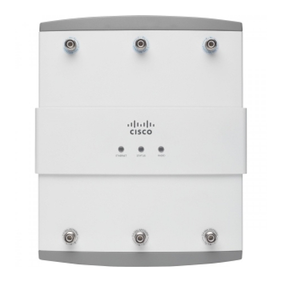
Before Beginning the Installation Before you begin the installation, refer to the illustrations on the following pages to become familiar with the access point and the mounting hardware Caution Be careful when handling the access point; the bottom plate might be hot. Caution The access point must be located indoors within the same building, including the associated LAN connections. - Page 11 ETHERNET STATUS RADIO 2.4-GHz radio antennas 5-GHz radio antennas 2.4-GHz radio module 5-GHz radio module LEDs Security lock slot (hidden) Quick Start Guide: Cisco Aironet 1250 Series Access Point...
- Page 12 This illustration shows LED placement. ETHERNET STATUS RADIO ETHERNET STATUS RADIO 78-17831-01...
- Page 13 This illustration shows the bottom of the access point with the mounting plate removed. 48vDC ETHERNET CONSOLE MODE Radio module latch Console port cable bay Ethernet cable bay Radio module latch Quick Start Guide: Cisco Aironet 1250 Series Access Point...
- Page 14 This illustration shows the connections inside the Ethernet and console port bays. CAUTION EXTERNAL DC AND INLINE PoE POWER SOURCE REQUIREMENTS DETERMINED BY INSTALLED RADIO MODULES REFER TO PRODUCT DOCUMENTATION +56VDC ETHERNET CONSOLE MODE DC power receptacle Console port (RJ-45) Ethernet port (RJ-45) Mode button 78-17831-01...
-
Page 15: Installation Summary
Configuring Power • Configuring Security Settings Mounting the Access Point Detailed mounting instructions are in the Cisco Aironet 1250 Series Access Point Hardware Configuration Guide. This document is available on Cisco.com. UL 2043 Compliance The access point has adequate fire resistance and low smoke-producing characteristics. -
Page 16: Connecting Power
Note The 1250 series power injector, 1250 series DC power module, and antennas are not tested to UL 2043 and should not be placed in a building’s environmental air space. Connecting Power The access point can be powered locally by the 1250 DC power module or an IEEE 802.3af compliant Power-over-Ethernet (PoE) power source. - Page 17 When the sequence is complete, you can obtain the access point’s IP address and perform an initial configuration. Refer to the “Obtaining and Assigning an IP Address” section on page 18 for instructions on assigning basic settings to the access point. Quick Start Guide: Cisco Aironet 1250 Series Access Point...
-
Page 18: Obtaining And Assigning An Ip Address
You can find out the DHCP-assigned IP address by using one of the following methods: – Connect to the access point console port and use a Cisco IOS command such as show interface bvi1 to display the IP address. 78-17831-01... -
Page 19: Connecting To The Access Point Locally
Set up a terminal emulator on your PC to communicate with the access point. Use the following settings for the terminal emulator connection: 9600 baud, 8 data bits, no parity, 1 stop bit, and no flow control. Quick Start Guide: Cisco Aironet 1250 Series Access Point... -
Page 20: Assigning An Ip Address Using The Cli
Assigning an IP Address Using the CLI When you assign an IP address to the access point using the CLI, you must assign the address to the BVI. Beginning in a privileged EXEC mode, follow these steps to assign an IP address to the access point BVI using the console port: Command Purpose... - Page 21 DC power module Option 2 Access Point Warning This product must be connected to a Power over Ethernet (PoE) IEEE 802.3af compliant power source or an IEC60950 compliant limited power source. Statement 353 Quick Start Guide: Cisco Aironet 1250 Series Access Point...
- Page 22 The access point power options: • Option 1—Switches with sufficient inline power (single radio only): – An inline power capable switch, such as the Cisco Catalyst 3550 PWR XL, 3560-48PS, 4500 with 802.3af PoE module, or the 6500 with 802.3af PoE module –...
-
Page 23: Connecting To An Ethernet Network With An Inline Power Source
Connect a Category 5E (or higher) Ethernet cable to the RJ-45 Ethernet connector labeled Ethernet on the access point. Step 2 Step 2 Connect the other end of the Ethernet cable to one of the following: Quick Start Guide: Cisco Aironet 1250 Series Access Point... -
Page 24: Connecting To An Ethernet Network With Local Power
– A switch with inline power. – The Ethernet connector on the 1250 series power injector labeled To Step 3 When using the power injector, connect a Category 5E (or higher) Ethernet cable from your your inline power switch to the power injector connector labeled To Switch. -
Page 25: Configuring The Access Point
This guide provides a brief synopsis of the configuration process. For detailed information, refer to the “Configuring the Access Point for the First Time” chapter of the Cisco IOS Software Configuration Guide for Cisco Aironet Access Points for the Cisco IOS release you are using. -
Page 26: Configuring Security Settings
The following basic settings must be configured on your access point. • Host Name • Configuration Server Protocol • IP Address • IP Subnet Mask • Default Gateway • SNMP Community The following radio settings must be applied separately to each radio. •... - Page 27 Basic security settings are explained in the “Configuring the Access Point for the First Time” chapter of the Cisco IOS Software Configuration Guide for Cisco Aironet Access Points for the Cisco IOS release you are using. The following security settings are available on the Express Security Setup page.
-
Page 28: In Case Of Difficulty
If you do experience difficulty, the following sections provide basic troubleshooting information. Before contacting Cisco, look for a solution to your problem in this guide or the “Troubleshooting” chapter of the Cisco Aironet 1250 Series Access Point Hardware Installation Guide. - Page 29 – – Blinking Software upgrade in progress. blue Blinking Blinking Blinking Access location command. green green green – – Blinking red Ethernet link not operational in FlexConnect mode. Quick Start Guide: Cisco Aironet 1250 Series Access Point...
- Page 30 – Software failure. – – Cycling General warning; insufficient blue, green, inline power. red, off For more details on these LED status codes, see the “Troubleshooting” chapter of the Cisco Aironet 1250 Series Access Point Hardware Installation Guide. 78-17831-01...
-
Page 31: Resetting To Default Configuration
Disconnect power from the access point (the power jack for external power or the Ethernet cable for in-line power). Step 3 Press and hold the MODE button while you reconnect power to the access point. Quick Start Guide: Cisco Aironet 1250 Series Access Point... -
Page 32: Using The Web Browser Interface
Step 4 Continue holding the MODE button until the Ethernet LED turns amber (approximately 2 to 3 seconds), then release the button. Step 5 After the access point reboots, you must reconfigure it using the web browser interface, the Telnet interface, or connecting to the access point console port. -
Page 33: Compliance Information
The Declarations of Compliance for this product relevant to the European Union and other countries following EU Directive 1999/5/EC (R&TTE Directive) can be found in the Cisco Aironet 1250 Series Access Point Hardware Installation Guide. This guide is available on Cisco.com. -
Page 34: Cisco 90-Day Limited Hardware Warranty Terms
Warranty Statement, including the warranties and license agreements applicable to Cisco software, is available on Cisco.com. Follow these steps to access and download the Cisco Information Packet and your warranty and license agreements from Cisco.com. 1. Launch your browser, and go to this URL: http://www.cisco.com/en/US/products/prod_warranties_listing.html... - Page 35 The Cisco warranty page appears. d. Review the document online, or click the PDF icon to download and print the document in Adobe Portable Document Format (PDF). You can also contact the Cisco service and support website for assistance: http://www.cisco.com/cisco/web/support/index.html. Duration of Hardware Warranty Ninety (90) days.
- Page 36 Replacement, Repair, or Refund Policy for Hardware Cisco or its service center will use commercially reasonable efforts to ship a replacement part within ten (10) working days after receipt of a Return Materials Authorization (RMA) request. Actual delivery times can vary, depending on the customer location.