Table of Contents
Advertisement
User's Manual
Model 336
Temperature Controller
Lake Shore Cryotronics, Inc.
sales@lakeshore.com
575 McCorkle Blvd.
service@lakeshore.com
Fax: (614) 891-1392
Westerville, Ohio 43082-8888 USA
www.lakeshore.com
Telephone: (614) 891-2243
Methods and apparatus disclosed and described herein have been developed solely on company funds of
Lake Shore Cryotronics, Inc. No government or other contractual support or relationship whatsoever has existed
which in any way affects or mitigates proprietary rights of Lake Shore Cryotronics, Inc. in these developments.
Methods and apparatus disclosed herein may be subject to U.S. Patents existing or applied for.
Lake Shore Cryotronics, Inc. reserves the right to add, improve, modify, or withdraw functions, design modifications,
or products at any time without notice. Lake Shore shall not be liable for errors contained herein or for incidental or
consequential damages in connection with furnishing, performance, or use of this material.
Rev. 1.9
P/N 119-048
7 December 2015
|
www.lakeshore.com
Advertisement
Chapters
Table of Contents
Troubleshooting

Related Manuals for Lakeshore 336


Summary of Contents for Lakeshore 336
- Page 1 User’s Manual Model 336 Temperature Controller Lake Shore Cryotronics, Inc. sales@lakeshore.com 575 McCorkle Blvd. service@lakeshore.com Fax: (614) 891-1392 Westerville, Ohio 43082-8888 USA www.lakeshore.com Telephone: (614) 891-2243 Methods and apparatus disclosed and described herein have been developed solely on company funds of Lake Shore Cryotronics, Inc.
- Page 2 Specifically, except as provided herein, Lake mandatory statutory rights applicable to the sale of the product Shore undertakes no responsibility that the products will be fit for any to you. particular purpose for which you may be buying the Products. Model 336 Temperature Controller...
- Page 3 Technology (NIST); formerly known as the National Bureau of Stan- terms of the Limited Warranty specified above. Any unauthorized dards (NBS). duplication or use of the Model 336 firmware in whole or in part, in print, or in any other storage and retrieval system is forbidden. FIRMWARE LIMITATIONS...
- Page 4 Model 336 Temperature Controller...
- Page 5 To qualify for the CE Mark, the Model 336 meets or exceeds the requirements of the European EMC Directive 89/336/EEC as a CLASS A product. A Class A product is allowed to radiate more RF than a Class B product and must include the follow- ing warning: WARNING:This is a Class A product.
- Page 6 Model 336 Temperature Controller...
-
Page 7: Table Of Contents
1.3 Model 336 Specifications ........ - Page 8 3.8.5.3 Connecting to the Model 336 ........
- Page 9 4.7 Locking and Unlocking the Keypad ..........71 www.lakeshore.com...
- Page 10 6.2.6.1 Status Byte Register ..........101 Model 336 Temperature Controller...
- Page 11 7.6 Input Option Card Installation ........... . 149 www.lakeshore.com...
- Page 12 C.1 General ................171 Curve Tables Model 336 Temperature Controller...
-
Page 13: Product Description
The Model 336 is the only temperature controller available with four sensor inputs, four control outputs, and 150 W of low noise heater power. Two independent... -
Page 14: Sensor Inputs
Temperature sensor calibration data can be easily uploaded and manipulated using the Lake Shore curve handler software. 1.1.2 Temperature Providing a total of 150 W of heater power, the Model 336 is the most powerful tem- perature controller available. Delivering very clean heater power, it precisely controls Control temperature throughout the full scale temperature range for excellent measurement reliability, efficiency, and throughput. -
Page 15: Interface
1.1.3 Interface The Model 336 is standard equipped with Ethernet, universal serial bus (USB) and parallel (IEEE-488) interfaces. In addition to gathering data, nearly every function of the instrument can be controlled through a computer interface. You can download the Lake Shore curve handler software to your computer to easily enter and manipu- late sensor calibration curves for storage in the instrument’s non-volatile memory. -
Page 16: Configurable Display
1: Introduction HAPTER 1.1.4 Configurable The Model 336 offers a bright, graphic liquid crystal display with an LED backlight that simultaneously displays up to 8 readings. You can show all 4 loops, or if you need Display to monitor 1 input, you can display just that one in greater detail. Or you can custom configure each display location to suit your experiment. - Page 17 Not recommended Chromel-AuFe 0.07% 9006-002 1.2 K to 610 K Not recommended Non-HT version maximum temperature: 325 K Low temperature limited by input resistance range Low temperature specified with self-heating error: " 5 mK TABLE 1-1 Sensor temperature range www.lakeshore.com...
- Page 18 Typical sensor sensitivities were taken from representative calibrations for the sensor listed Control stability of the electronics only, in an ideal thermal system Non-HT version maximum temperature: 325 K Accuracy specification does not include errors from room temperature compensation TABLE 1-2 Typical sensor performance Model 336 Temperature Controller...
-
Page 19: Model 336 Specifications
1.3 Model 336 Specifications 1.3 Model 336 Specifications 1.3.1 Input Specifications Standard Sensor Input Range Excitation Display Measurement Electronic Measurement Temperature Electronic inputs and Tempera- Current Resolution Resolution Accuracy Coefficient Control Stability scanner option ture Coeffi- (at 25 °C) Model 3062... -
Page 20: Sensor Input Configuration
Improves accuracy of DT-470 diode to ±0.25 K from 30 K to 375 K; improves accuracy of platinum RTDs to ±0.25 K from 70 K to 325 K; stored as user curves Math Maximum and minimum Filter Averages 2 to 64 input readings Model 336 Temperature Controller... -
Page 21: Control
3 (decade steps in power) Heater noise 0.12 µA RMS (dominated by line frequency and its harmonics) Grounding Output referenced to chassis ground Heater connector Dual banana Safety limits Curve temperature, power up heater off, short circuit protection TABLE 1-8 Output 2 www.lakeshore.com... -
Page 22: Unpowered Analog Outputs (Outputs 3 And 4)
Heater output resolution 0.01% Display annunciators Control input, alarm, tuning LED annunciators Remote, Ethernet status, alarm, control outputs Keypad 27-key silicone elastomer keypad Front panel features Front panel curve entry, display contrast control, and keypad lock-out Model 336 Temperature Controller... -
Page 23: Interface
100, 120, 220, 240, VAC, ±10%, 50 or 60 Hz, 250 VA Size 435 mm W × 89 mm H × 368 mm D (17 in × 3.5 in × 14.5 in), full rack Weight 7.6 kg (16.8 lb) Approval CE mark www.lakeshore.com... -
Page 24: Safety Summary And Symbols
Lake Shore Cryotronics, Inc. assumes no liability for Cus- tomer failure to comply with these requirements. The Model 336 protects the operator and surrounding area from electric shock or burn, mechanical hazards, excessive temperature, and spread of fire from the instru- ment. - Page 25 Three-phase alternating current (power line) yellow; symbol and outline: black Earth (ground) terminal CAUTION or WARNING: See instrument documentation; background color: yellow; Protective conductor terminal symbol and outline: black Frame or chassis terminal On (supply) Off (supply) 1-4 Safety symbols FIGURE www.lakeshore.com...
- Page 26 1: Introduction HAPTER Model 336 Temperature Controller...
-
Page 27: General
Another thing to consider when choosing a temperature sensor is that instruments like the Model 336 are not able to read some sensors over their entire temperature range. Lake Shore sells calibrated sensors that operate down to 20 millikelvin (mK), but the Model 336 is limited to above 300 mK in its standard configuration. -
Page 28: Environmental Conditions
2.3 Sensor It can sometimes be confusing to choose the right sensor, get it calibrated, translate the calibration data into a temperature response curve that the Model 336 can Calibrations understand, and then load the curve into the instrument. Lake Shore provides a vari- ety of calibration services to fit different accuracy requirements and budgets. -
Page 29: Precision Calibration
Model 336 user curve loca- tions. You can also use it to read curves from the Model 336 and save them to files. Lake Shore calibrated sensors are provided with a CD containing all the proper for- mats to load curves using the Curve Handler™... -
Page 30: Sensor Installation
Ethernet web interface on the Model 336. This version allows you to copy curves from files to the Model 336, and vice versa, but it does not allow manipulation of curve data and only works using the Ethernet interface. Refer to section 6.4.4 for details on connecting to the web interface and opening the... -
Page 31: Contact Area
Thin wire insulation is preferred, and twisted wire should be used to reduce the effect of RF noise if it is present. The wire used on the room temperature side of the vacuum boundary is not critical, so copper cable is normally used. www.lakeshore.com... -
Page 32: Lead Soldering
Many cooling systems include a radiation shield. The purpose of the shield is to sur- round the sample stage, sample, and sensor with a surface that is at or near their tem- perature to minimize radiation. The shield is exposed to the room temperature Model 336 Temperature Controller... -
Page 33: Heater Selection And Installation
2.5.1 Heater Resistance Cryogenic cooling systems have a wide range of cooling power. The resistive heater must be able to provide sufficient heating power to warm the system. The Model 336 and Power can provide up to 100 W of power from Output 1 and up to 50 W of power from Output 2. -
Page 34: Heater Location
It is possible to choose a heater value that results in a maximum power greater than the power rating of 50 W for output 2, but doing so can cause the Model 336 to work improp- erly. In this situation the max user current setting should be used to limit the power. Refer to section 4.5.1.1.1 for details on using the max user current setting. -
Page 35: Consideration For Good Control
If both control stability and measurement accuracy are critical it may be necessary to use two sensors, one for each function. Many tempera- ture controllers including the Model 336 have multiple sensor inputs for this reason. 2.6.4 Thermal Mass Cryogenic designers understandably want to keep the thermal mass of the load as small as possible so the system can cool quickly and improve cycle time. -
Page 36: Pid Control
As discussed in section 2.8.3, measuring this time constant allows a reasonable calculation of the integral setting. In the Model 336, the integral term is not set in seconds like some other systems. The integral setting can be derived by... -
Page 37: Derivative (D)
I-setting when used. 2.7.4 Manual Output The Model 336 has a control setting that is not a normal part of a PID control loop. Manual Output can be used for open loop control, meaning feedback is ignored and the heater output stays at the user's manual setting. - Page 38 2: Cooling System Design and Temperature Control HAPTER FIGURE 2-2 Examples of PID control Model 336 Temperature Controller...
-
Page 39: Manual Tuning
Lower heater ranges are normally needed for lower temperature. The Model 336 is of no use controlling at or below the temperature reached when the heater was off. Many systems can be tuned to control within a degree or two above that temperature. -
Page 40: Tuning Integral
2. Use the oscillation period of the load that was measured in section 2.8.2 in sec- onds. Divide 1000 by the oscillation period to get the integral setting. 3. Enter the integral setting into the Model 336 and watch the load temperature approach the setpoint. -
Page 41: Tuning Derivative
D. Autotune works only with one control loop at a time and does not set the man- ual output or heater range. Setting an inappropriate heater range is potentially dan- gerous to some loads, so the Model 336 does not automate that step of the tuning process. -
Page 42: Zone Tuning
Trying to remember when to use which set of tuning parameters can be difficult. The Model 336 has a Zone feature as one of its tuning modes that can help. -
Page 43: General
* Included only when purchased with VAC-120-ALL power option. 3.3 Rear Panel This section provides a description of the Model 336 rear panel connections. The rear panel consists of the Input A, B, C, and D sensor input connectors (#1 in FIGURE 3-1),... -
Page 44: Line Input Assembly
3.4.2 Line Fuse and The line fuse is an important safety feature of the Model 336. If a fuse ever fails, it is important to replace it with the value and type indicated on the rear panel for the line Fuse Holder voltage setting. -
Page 45: Power Cord
3.4.4 Power Switch The power switch is part of the line input assembly on the rear panel of the Model 336 and turns line power to the instrument on and off. When the circle is depressed, power is off. -
Page 46: Sensor Lead Cable
A shield is most effective when it is near the measurement potential so the Model 336 offers a shield at measurement common. The shield of the sensor cable should be connected to the shield pin of the input connector. The shields should not be connected to earth ground on the instrument chassis. -
Page 47: Four-Lead Sensor Measurement
50 mK. Again, this may not be a problem for every user. Connectors are also a big source of error when making two-lead measurements. Connector contact resistance is unpredictable and changes with time and temperature. Minimize interconnections when making two-lead measurements. Refer to FIGURE 3-6 for an image of a two- lead sensor measurement. www.lakeshore.com... -
Page 48: Lowering Measurement Noise
Refer to section 7.6 for installation of the Model 3061. The Model 3061 adds a capacitance input to the Model 336, appearing on the display as input D. The card has separate voltage feedback and current excitation for the sen- sor. -
Page 49: Wiring, Guarding And Shielding
Test any system for sensor interference before it is permanently sealed 3.7 Thermocouple The information in this section is for a Model 336 configured with thermocouple sen- sor inputs. Thermocouple inputs are not installed on the standard Model 336, but can Sensor Inputs be added by purchasing the Model 3060 dual thermocouple input option. -
Page 50: Thermocouple Installation
Heater power is applied in one of three ranges: high, med, or low. Each range is one decade lower in power. Refer to TABLE 4-14 for maximum current and power ratings into different heater resistance. Model 336 Temperature Controller... -
Page 51: Heater Output Connectors
Also avoid connecting heater leads to sensor leads or any other instrument inputs or outputs. 3.8.4 Heater Output The heater output circuitry in the Model 336 is capable of sourcing 100 W of power. This type of circuitry can generate some electrical noise. The Model 336 was designed Noise... -
Page 52: Choosing A Power Supply
DC output. Output Type: most available voltage programmable power supplies are configured for voltage output. This is different than Outputs 1 and 2 on the 336 which are configured for current output. The differences between the two are not signifi- cant when used in warm up mode. -
Page 53: Connecting To The Model 336
R1 to R2: Vout = 10V x R1/(R1+R2). It is also important to keep the sum of R1 + R2 > 1000 ) or the Model 336 output may not reach the output voltage setting due to internal overload protection. For a programming input range of 0 V to 5 V, recom- mended values are: R1 = R2 = 2000 ). - Page 54 3: Installation HAPTER Model 336 Temperature Controller...
-
Page 55: General
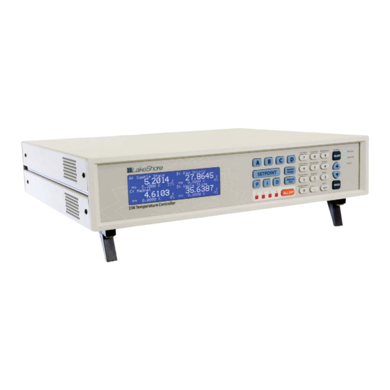
Chapter 4: Operation 4.1 General This chapter provides instructions for the general operating features of the Model 336 temperature controller. Advanced operation is in Chapter 5. Computer interface instructions are in Chapter 6. FIGURE 4-1 Model 336 front panel 4.1.1 Understanding Each feature that is discussed in this chapter will include a menu navigation section. -
Page 56: Front Panel Description
(FIGURE 4-1). The Direct Operation keys provide one touch access to the most often used functions of the Model 336. The Number Pad keys, with the exception of the dec- imal point key, are dual function keys. If the instrument is in the number entry mode, the keys are used to enter numbers. -
Page 57: Menu/Number Pad Keys
On steady when the corresponding output is in the On state (does not apply to Monitor Out mode). Control outputs 4.5.1.4 Off when corresponding output is in the Off state, or when it is set to Monitor Out mode. TABLE 4-4 LED annunciators www.lakeshore.com... -
Page 58: General Keypad Operation
+/-, to enter that character into the string and advance the cursor to the next position automatically, or to save the string and return to Menu Navigation mode if in the last position. Use the +/- key to enter the whitespace character. Model 336 Temperature Controller... -
Page 59: Display Setup
The intuitive front panel layout and keypad logic, bright, graphic display, and LED indicators enhance the user-friendly front panel interface of the Model 336. The Model 336 offers a bright, graphic, liquid, crystal display, with an LED backlight that simultaneously displays up to eight readings. -
Page 60: All Inputs Mode
Interface Command: DISPLAY 4.3.1.3 Input Display Modes An Input Display mode exists for each of the four sensor inputs on the Model 336. These modes are referenced as Input A, Input B, Input C, and Input D in the Display Mode parameter list. -
Page 61: Custom Display Mode
LCD depends on the Number of Displays setting (FIGURE 4-5). FIGURE 4-5 Top to bottom: Model 336 screen images showing 2, 4 and 8 display locations Number of Custom display locations: the Number of Displays parameter determines how many sensor readings are displayed, as well as the character size of the dis- played readings. - Page 62 Loop, but will be displayed even for outputs that are not con- figured as control loop outputs. Menu Navigation: Display Setup QDisplayed OutputQOutput (1, 2, 3, 4) Default: Output 1 Interface Command: DISPLAY Model 336 Temperature Controller...
-
Page 63: Display Contrast
Interface Command: BRIGT 4.4 Input Setup The Model 336 supports a variety of temperature sensors manufactured by Lake Shore and other manufacturers. An appropriate sensor type must be selected for each input. If the exact sensor model is not shown, use the sensor input performance chart in TABLE 4-7 to choose an input type with similar range and excitation. -
Page 64: Diode Sensor Input Setup
4.4.2 Positive PTC resistor sensors include the platinum and rhodium-iron sensors detailed in TABLE 4-7. More detailed specifications are provided in TABLE 1-2. The Model 336 Temperature supplies a 1 mA excitation current for the PTC resistor sensor type. A resistance range Coefficient (PTC) selection is available in order to achieve better reading resolution. -
Page 65: Thermal Electromotive Force (Emf) Compensation
Even in a well-designed system thermal EMF volt- ages can be an appreciable part of a low voltage sensor measurement. The Model 336 can help with a thermal compensation algorithm. The instrument will automatically reverse the polarity of the current source every other reading. The average of the positive and negative sensor readings will cancel the thermal EMF voltage that is present in the same polarity, regardless of current direction. -
Page 66: Thermocouple Sensor Input Setup (Model 3060 Only)
4: Operation HAPTER 4.4.6 Thermocouple When a Model 3060 Thermocouple option is installed in the Model 336, a setting of Thermocouple becomes available under the Sensor Type parameter in the Input Sensor Input Setup Setup menu. The standard diode/RTD sensor inputs can still be used when the Ther-... -
Page 67: Capacitance Sensor Input Setup (Model 3061 Only)
Input SetupQRoom CalibrationQClear Calibration Default: Room calibration cleared 4.4.7 Capacitance When a Model 3061 capacitance option is installed in the Model 336, a setting of Capacitance becomes available under the Sensor Type parameter in the Input Setup Sensor Input Setup menu. -
Page 68: Temperature Coefficient Selection
Control parameters, P and I, may need to be changed for stable control. 4.4.8 4-Channel When a Model 3062 4-Channel Scanner option is installed in the Model 336, 4 addi- tional channels, D2, D3, D4, and D5, become available for use. The channels are Scanner Input Setup scanned with the Model 336’s Input D at a reduced update rate. -
Page 69: Update Rate
SoftCal™ calibrations are stored as user curves, or you can enter your own curves from the front panel (section 5.8) or computer interface (sec- tion 6.4). The complete list of sensor curves preloaded in the Model 336 is provided in TABLE 4-11. -
Page 70: Filter
The default number of filter points is 8, which settles to within six time constants of a step change value in 45 readings, or 4.5 s. Model 336 Temperature Controller... - Page 71 Model 3062 4-channel scanner option card Menu Navigation: Input SetupQInput (A, B, C or D)QFilterQ(Off or On) Input SetupQInput (A, B, C or D)QFilter PointsQ(2 to 64) Input SetupQInput (A, B, C or D)QFilter WindowQ(1% to 10%) Default: FilterQ(Off) Filter PointsQ8 Filter WindowQ10% www.lakeshore.com...
-
Page 72: Input Name
HAPTER 4.4.11 Input Name To increase usability and reduce confusion, the Model 336 provides a means of assigning a name to each of the four sensor inputs. The designated input name is used on the front panel display whenever possible to indicate which sensor reading is being displayed. -
Page 73: Heater Outputs
The power ranges for each output provide decade steps in power. 4.5.1.1 Max Current and Heater Resistance The Model 336 heater outputs are designed to work optimally into a 25 ) or 50 ) heater. The Heater Resistance and Max Current parameters work together to limit the maximum available power into the heater. - Page 74 Bold: Discrete options available for 25 ) and 50 ) heaters under the Max Current setting TABLE 4-14 User Max Current Menu Navigation: Output SetupQOutput (1 or 2)QUser Max CurrentQ(0.1 A to 2 A) Default: Output 1QUser Max CurrentQ2 A Output 2QUser Max CurrentQ1.414 A Model 336 Temperature Controller...
-
Page 75: Power Up Enable
4.5.1 Heater Outputs 4.5.1.2 Power Up Enable All configuration parameters of the Model 336 can be retained through a power cycle. Some systems require that the Heater Range is turned off when power is restored. The power up enable feature allows you to choose whether or not the heater range is turned off each time the instrument power is cycled. -
Page 76: Zone Mode
Heater Range is used to turn on the control output, as well as to set the power range of the output. These parameters are described in detail in section 4.5.1.5.1 to section 4.5.1.5.8. Model 336 Temperature Controller... -
Page 77: Control Input
A, B, C, or D on the front panel to temporarily display the control loop information while the new setting is entered. Refer to section 4.3 for details on configuring the front panel display. Menu Navigation: IQ(0 to 1000) Default: 20 Interface Command: PID www.lakeshore.com... -
Page 78: Derivative (D)
1/i the integral time in seconds, if used at all. As a convenience to the operator, the Model 336 derivative time constant is expressed in percent of ¼ the integral time. The range is between 0% and 200%. Start with settings of 0%, 50%, or 100%, and determine which setting gives you the type of control you desire. -
Page 79: Setpoint
For these applications the Model 336 can control temperature in sensor units. To control in sensor units, set the Preferred Units parameter to Sensor. When controlling in sensor units, the Setpoint resolution matches the display resolution for the sensor input type given in the speci- fications (section 1.3). -
Page 80: Setpoint Ramping
HAPTER 4.5.1.5.7 Setpoint Ramping The Model 336 can generate a smooth setpoint ramp when the setpoint units are expressed in temperature. You can set a ramp rate in degrees per minute with a range of 0 to 100 and a resolution of 0.1. Once the ramping feature is turned on, its action is initiated by a setpoint change. -
Page 81: Heater Range
A, B, C, or D on the front panel to temporarily display the control loop informa- tion while the new setting is entered. Refer to section 4.2 for details on configuring the front panel display. Menu Navigation: Heater RangeQ(Off, On, Low, Med, High) Default: Off Interface Command: RANGE www.lakeshore.com... -
Page 82: All Off
USB interface is provided on nearly all new PCs as of the writing of this manual. The Model 336 USB driver, which must be installed before using the inter- face (section 6.3.3), creates a virtual serial com port, which can be used in the same way as a traditional serial com port. -
Page 83: Ethernet
The advantages of using the Ethernet interface include the ability to communi- cate directly with the Model 336 from any PC on the same local network, and even from around the world via the internet. Refer to section 6.4.1 for details on Ethernet configuration. - Page 84 4: Operation HAPTER Model 336 Temperature Controller...
-
Page 85: General
5.1 General Chapter 5: Advanced Operation 5.1 General This chapter provides information on the advanced operation of the Model 336 tem- perature controller. 5.2 Autotune The Model 336 can automate the tuning process of typical cryogenic systems with the Autotune feature. For additional information about the algorithm refer to section 2.9. - Page 86 PI and PID Autotuning Autotune heater range control parameters TABLE 5-1 Autotune stages Menu Navigation: AutotuneQInput (A, B, C, D)Q(Autotune P, Autotune PI, Autotune PID) Model 336 Temperature Controller...
-
Page 87: Zone Settings
5.3 Zone Settings 5.3 Zone Settings The Model 336 allows you to establish up to ten custom contiguous temperature zones where the controller will automatically use pre-programmed values for PID, heater range, manual output, ramp rate, and control input. Zone control can be active for both control loops at the same time. - Page 88 Control Input A Off A Med A Default (0.1–1000) (0.1–1000) (0–200) (0–100%) (0.1–100 K/min) Zone 01 A Low A High FIGURE 5-1 Record of Zone settings Menu Navigation: ZonesQOutput (1 or 2)QZonesQ(1 to 10) Interface Command: ZONE Model 336 Temperature Controller...
-
Page 89: Bipolar Control
For these types of bipolar devices, the Model 336 features a bipolar control mode. In this mode, the Model 336 is configured to drive these devices to control temperature using Output 3 and 4. -
Page 90: Warm Up Control
The Monitor Out scaling parameter set- tings are entered using the units chosen for this parameter. Menu Navigation: Output SetupQOutput (3 or 4)QMonitor UnitsQ(K, C, or Sensor) Default: K Interface Command: ANALOG Model 336 Temperature Controller... -
Page 91: Polarity And Monitor Out Scaling Parameters
Monitor Out -10 V, 0 V, and +10 V settings depend on the Monitor Units selected, and are limited to the acceptable values of the selected units. Default: PolarityQUnipolar Monitor Out -10 VQ0.0000 K Monitor Out 0 VQ0.0000 K Monitor Out +10 VQ1000 K Interface Command: ANALOG www.lakeshore.com... -
Page 92: Alarms And Relays
The two relays on the Model 336 can also be tied to alarm functions as described in section 5.7.2. You may want to set the Visible parameter to Off if there is no need for showing the alarm state on the front panel, for instance, if you are using the alarm function to trig- ger a relay. - Page 93 No to enter the Alarm Setup menu. Menu Navigation: AlarmQInput (A, B, C, D)QLatchingQ(Off, On) AlarmQInput (A, B, C, D)QDeadbandQ(see note below) Low and High Setpoint limits are determined by the Preferred Units of the associated sensor input. Default: LatchingQOff DeadbandQ1.0000 K Interface Command: ALARM www.lakeshore.com...
-
Page 94: Relays
HAPTER 5.7.2 Relays There are two relays on the Model 336 numbered 1 and 2. They are most commonly thought of as alarm relays, butthey may be manually controlled also. Relay assign- ments are configurable as shown in FIGURE 5-6. Two relays can be used with one sen- sor input for independent high and low operation, or each can be assigned to a different input. -
Page 95: Curve Header Parameters
5.8.1 Curve Header Parameters The Model 336 has 39 user curve locations, numbered 21 through 59. Each location can hold from 2 to 200 data pairs (breakpoints), including a value in sensor units and a corresponding value in kelvin. Using fewer than 200 breakpoints will not increase the number of available curve locations. -
Page 96: Front Panel Curve Entry Operations
Enter the breakpoints with the sensor units value increasing as point number increases. There should not be any breakpoint locations left blank in the middle of a curve. The search routine in the Model 336 interprets a blank breakpoint as the end of the curve. -
Page 97: Edit A Breakpoint Pair
FIGURE 5-7 Left: Scroll to highlight a breakpoint number; Middle: Press the enter key to highlight the sensor value of the selected pair ; Right: Press the enter key again, and the temperature value is highlighted Menu Navigation: Curve Entry QEdit CurveQ (21–59)QCurve Points Q(1–200) Interface Command: CRVPT www.lakeshore.com... -
Page 98: Add A New Breakpoint Pair
To convert curves published in Celsius to kelvin, add 273.15 to the temperature in Celsius. The input voltage of the Model 336 is limited to ±50 mV, so any part of the curve that extends beyond ±50 mV is not usable by the instrument. -
Page 99: View Curve
Interface Command: CRDEL 5.9.4 Copy Curve Temperature curves can be copied from one location inside the Model 336 to another. This is a good way to make small changes to an existing curve. Curve copy may also be necessary if you need the same curve with two different temperature limits or if you need to extend the range of a standard curve. -
Page 100: Softcal
Both DT-400 Series and platinum SoftCal™ algorithms require a standard curve that is already present in the Model 336. When you enter the type of sensor being cali- brated, the correct standard curve must be selected. When calibration is complete, you must assign the new curve to an input. -
Page 101: Softcal™ Accuracy With Dt-400 Series Silicon Diode Sensors
2 K to <30 K ±0.25 K 30 K to <60 K ±0.15 K 60 K to <345 K ±0.25 K 345 K to <375 K ±1.0 K 375 to 475 K TABLE 5-7 3-point SoftCal™ calibration accuracy for DT-470-SD-13 diode sensors www.lakeshore.com... -
Page 102: Softcal™ With Platinum Sensors
Three-point SoftCal™ calibrations are performed at liquid nitrogen (77.35 K), room temperature (305 K), and high temperature (480 K). Accuracy for the PT-102, PT-103, or PT-111 platinum sensor is ±250 mK from 70 K to 325 K, and ±250 mK from 325 K to 480 K. Model 336 Temperature Controller... -
Page 103: Softcal™ Calibrationcurve Creation
Refer to section 4.4.11 for details on assigning a curve to a sensor input. Menu Navigation: Curve Entry QSoftcalQ(DT-470, Platinum 100, Platinum 1000)QData Entry (see note below)Q(Generate Softcal)Q (Yes) Interface Command: SCAL Data entry includes new curve serial number and calibration points. www.lakeshore.com... - Page 104 5: Advanced Operation HAPTER Model 336 Temperature Controller...
-
Page 105: General
Cable lengths are limited to 2 m (6.6 ft) for each device and 20 m (65.6 ft) for the entire bus. The Model 336 can drive a bus with up to ten loads. If more instruments or cable length is required, a bus expander must be used. -
Page 106: Changing Ieee-488 Interface Parameters
LLO (Local Lockout): prevents the use of instrument front panel controls DCL (Device Clear): clears Model 336 interface activity and puts it into a bus idle state Finally, addressed bus control commands are multiline commands that must include the Model 336 listen address before the instrument responds. -
Page 107: Common Commands
Most device specific com- mands also work if performed from the front panel. Model 336 device specific com- mands are detailed in section 6.6.1 and summarized in TABLE 6-6. -
Page 108: Status System Overview
6: Computer Interface Operation HAPTER 6.2.4 Status System The Model 336 implements a status system compliant with the IEEE-488.2 standard. The status system provides a method of recording and reporting instrument informa- Overview tion and is typically used to control the Service Request (SRQ) interrupt line. A dia- gram of the status system is shown in FIGURE 6-1. - Page 109 CAL = Calibration error ATUNE = Autotune process completed NRDG = New sensor reading RAMP1 = Loop 1 ramp done RAMP2 = Loop 2 ramp done OVLD = Sensor overload ALARM = Sensor alarming FIGURE 6-1 Model 336 status system www.lakeshore.com...
-
Page 110: Status Byte Register
To program an enable register, send a decimal value that corresponds to the desired binary-weighted sum of all bits in the register (TABLE 6-2). The actual commands are described throughout (section 6.2.4). Model 336 Temperature Controller... -
Page 111: Clearing Registers
TABLE 6-3 Register clear methods 6.2.5 Status System As shown in FIGURE 6-1, there are two register sets in the status system of the Model 336: Standard Event Status Register and Operation Event Register. Detail: Status Register Sets 6.2.5.1 Standard Event Status Register Set... -
Page 112: Operation Event Register Set
Sensor Overload (OVLD), Bit (1): this bit is set when a sensor reading is in the over- load condition Alarming (ALARM), Bit (0): this bit is set when an input is in an alarming state, and the Alarm Visible parameter is on Model 336 Temperature Controller... -
Page 113: Status System Detail: Status Byte Register And Service Request
Service Request Enable Register. Event Summary (ESB), Bit (5): this bit is set when an enabled standard event has occurred Message Available (MAV), Bit (4): this bit is set when a message is available in the output buffer www.lakeshore.com... -
Page 114: Service Request Enable Register
The serial poll does not clear MSS. The MSS bit stays set until all enabled Status Byte summary bits are cleared, typically by a query of the associated event register (section 6.2.6.4). The programming example in TABLE 6-4 initiates an SRQ when a command error is detected by the instrument. Model 336 Temperature Controller... -
Page 115: Using Status Byte Query (*Stb?)
The bus controller can, for example, send a query command to the Model 336 and then wait for MAV to set. If the MAV bit has been enabled to initiate an SRQ, the user’s program can direct the bus controller to look for the SRQ leaving the bus available for other use. -
Page 116: Usb Interface
USB peripheral devices, and it allows the common USB A-type to Connection B-type cable to be used to connect the Model 336 to a host PC. The pin assignments for A-type and B-type connectors are shown in section 8.10. The maximum length of a USB cable, as defined by the USB 2.0 standard, is 5 m (16.4 ft). -
Page 117: Installing The Driver From Windows® Update In Windows® Xp
If the Found New Hardware wizard is unable to connect to Windows® Update or find the drivers, a message to “Insert the disc that came with your Lake Shore Model 336” will be displayed. Click Cancel and refer to section 6.3.3.3 to install the driver from the web. -
Page 118: Manually Install The Driver
Lake Shore Model 336 should appear indented underneath Other Devices. If it is not displayed as Lake Shore Model 336, it might be displayed as USB Device. If neither are displayed, click Action and then Scan for hardware changes, which may open the Found New Hardware wizard automatically. -
Page 119: Installing The Usb Driver From The Included Cd
+ icon. Lake Shore Model 336 should appear indented underneath Ports (COM & LPT). If it is not displayed as Lake Shore Model 336, it might be displayed as USB Device. If neither are displayed, click Action and then select Scan for hardware changes, which may open the Found New Hardware wizard automatically. -
Page 120: Character Format
A special ASCII character, line feed (LF 0AH), is used to indicate the end of a mes- sage string. This is called the message terminator. The Model 336 will accept either the line feed character alone, or a carriage return (CR 0DH) followed by a line feed as the message terminator. -
Page 121: Ethernet Interface
Ethernet devices and the Model 336. The IP version used by the Model 336 is IPv4. The IPv6 standard is not supported. All references to the IP protocol from this point forward will be referring to IPv4. -
Page 122: Network Addresss Configuration Methods
DHCP server fails, the Model 336 then checks if Auto-IP is enabled. If Auto-IP is enabled, this method will be used. If disabled, or if this attempt fails, the Static-IP method will be used. If the Static-IP method fails, the IP address parameters will not be configured and the Ethernet status will enter an error state. -
Page 123: Dns Parameters
To use Static-IP to manually config- ure the IP address, subnet mask, and gateway of the Model 336, set the DHCP and the Auto-IP parameters to Off. Refer to the paragraphs above for details on turning off DHCP and Auto-IP. - Page 124 A hostname can be assigned by a network administrator, or if the Model 336 is con- nected to a network with Dynamic DNS (DDNS) capability, a DNS entry is automati- cally created for it using the Preferred Hostname and Preferred Domain Name parameters and the assigned IP address.
-
Page 125: Viewing Ethernet Configuration
6.4.2 Viewing Ethernet Configuration If the Model 336 is connected to a network with Dynamic DNS (DDNS) capability, a DNS entry is automatically created using the Preferred Hostname and Preferred Domain Name parameters and the assigned IP address. The Preferred Domain Name parameter can only be accessed using the NET interface command (section 6.6.1), or... -
Page 126: Mac Address
The port number used for TCP socket connections on the Model 336 is 7777. A maximum of two simultaneous socket connections can be made to the Model 336. Any attempts to open a new socket while two socket connections are already open on a Model 336 will fail. -
Page 127: Embedded Web Interface
6.4.4 Embedded Web Interface 6.4.4 Embedded Web The Model 336 provides a web interface via an embedded web server that runs on the instrument. Once the Model 336 is properly connected, and the IP parameters prop- Interface erly configured, the web interface can be opened using a web browser. The web inter- face should be accessible using any modern web browser, but has only been tested with Microsoft™... - Page 128 6: Computer Interface Operation HAPTER Ethernet Configuration Page: provides a means of reconfiguring the Ethernet config- uration parameters of the Model 336. FIGURE 6-6 Ethernet configuration page Ethernet Status Page: provides status and statistics related to the current Ethernet connection.
-
Page 129: Utilities
Model 336. The utility is also capable of reading curves from the Curve Handler™ Model 336 and writing them to a file for storage, or manipulation in a third party pro- gram. The Embedded Curve Handler™ supports standard Lake Shore temperature curve files in the “.340”... -
Page 130: Ethernet Firmware Updater
6.5.2 Ethernet The Ethernet Firmware Updater utility provides a means of updating the firmware that controls the Ethernet functionality of the Model 336. It also updates the embed- Firmware Updater ded website and the Java™ utilities found on the Utilities web page. Please visit www.lakeshore.com for the latest firmware updates. -
Page 131: Instrument Configuration Backup Utility
At this point the application should check to see if the firmware you are attempting to update to is newer than what is already installed on the Model 336. If it is, then the firmware should immediately begin uploading, and the progress of the firmware update operation should be displayed using the two progress bars in the application window. -
Page 132: Embedded Chart Recorder
Model 336. A basic user interface is also provided for changing control parameters on the fly while acquiring data, allowing many basic experiments to be performed without ever having to write any custom software. -
Page 133: Starting Data Acquisition
If a note is saved while not currently logging data to a file, the note will only appear in the note history text box, and will only be avail- able while the application is running. www.lakeshore.com... -
Page 134: Menu
Datapoint (4)—the current datapoint number. If logging data, this also shows the total number of data points to be taken in the current data acquisition (i.e. 522 of 1000). Log File (5)—the file path of the file that is currently being used to log data. Model 336 Temperature Controller... -
Page 135: Command Summary
Form of the query input Input Curve Number Query INCRV? <input>[term] Input: Syntax of user parameter input* Format: see key below <input> Specify input: A–D Definition of returned parameter Returned: <curve number>[term] Format: Syntax of returned parameter FIGURE 6-13 Sample query format www.lakeshore.com... - Page 136 WEBLOG? Website Login Parameter Query INNAME Sensor Input Name Cmd ZONE Control Loop Zone Table Parameter Cmd INNAME? Sensor Input Name Query ZONE? Output Zone Table Parameter Query INTSEL Interface Select Cmd TABLE 6-6 Command summary Model 336 Temperature Controller...
-
Page 137: Interface Commands
Standard Event Status Register Query ESR?[term] Input Returned <bit weighting> Format Remarks The integer returned represents the sum of the bit weighting of the event flag bits in the Standard Event Status Register. Refer to section 6.2.5 for a list of event flags. www.lakeshore.com... -
Page 138: Idn? Identification Query
To enable status flags 4, 5, and 7, send the command *SRE 208[term]. 208 is the sum of the bit weighting for each bit. Bit Weighting Event Name Total: SRE? Service Request Enable Register Query SRE?[term] Input Returned <bit weighting>[term] Format nnn (Refer to section 6.2.6 for a list of status flags) Model 336 Temperature Controller... -
Page 139: Stb
Returned <status>[term] Format <status> 0 = no errors found, 1 = errors found Remarks The Model 336 reports status based on test done at power up. WAI Wait-to-Continue Command WAI[term] Input Remarks Causes the IEEE-488 interface to hold off until all pending operations have been com- pleted. -
Page 140: Alarm? Input Alarm Parameter Query
ANALOG command is the same as the <input> parameter in the OUT- MODE command. It is included in the ANALOG command for backward compatibility with previous Lake Shore temperature monitors and controllers. The ANALOG com- mand name is also named as such for backward compatibility. Model 336 Temperature Controller... -
Page 141: Analog? Monitor Out Parameter Query
TUNEST? query can be used to check if an Autotune error occurred. BRIGT Display Contrast Command Input BRIGT <contrast value>[term] Format <contrast value> 1–32 Remarks Sets the display contrast for the front panel LCD. BRIGT? Display Contrast Query Input BRIGT?[term] Returned <contrast value>[term] Format nn (refer to command for description) www.lakeshore.com... -
Page 142: Crdg? Celsius Reading Query
DT-470, serial number of 00011134, data format of volts versus kelvin, upper temperature limit of 325 K, and negative coefficient. CRVHDR? Curve Header Query Input CRVHDR? <curve>[term] Format <curve> Valid entries: 1–59. Returned <name>,<SN>,<format>,<limit value>,<coefficient>[term] Format s[15],s[10],n,+nnn.nnn,n (refer to command for description) Model 336 Temperature Controller... -
Page 143: Crvpt
The 10 µA excitation current is the only calibrated excitation current, and is used in almost all applications. Therefore the Model 336 will default the 10 µA current set- ting any time the input sensor type is changed in order to prevent an accidental change. -
Page 144: Dispfld
Output 1. Remarks The <num fields> and <displayed output> commands are ignored in all display modes except for Custom. DISPLAY? Display Setup Query Input DISPLAY?[term] Returned <mode>,<num fields>,<output source>[term] Format n,n,n (refer to command for description) Model 336 Temperature Controller... -
Page 145: Filter
Max current will be limited to 1.414 A on output 2 if the heater resistance is set to 25 ), and will be limited to 1 A on both outputs 1 and 2 if the heater resistance is set to 50 ). www.lakeshore.com... -
Page 146: Htrset? Heater Setup Query
INCRV A,23[term]—Input A uses User Curve 23 for temperature conversion. INCRV? Input Curve Number Query Input INCRV? <input>[term] Format <input> Specifies which input to query: A–D (D1–D5 for 3062 option). Returned <curve number>[term] Format nn (refer to command for description) Model 336 Temperature Controller... -
Page 147: Inname
Remarks ration parameters, which can be set using the NET command. Configuring the Ether- net interface parameters prior to enabling the interface is recommended. INTSEL? Interface Select Query Input INTSEL?[term] Returned <interface>[term] Format n (refer to command for description) www.lakeshore.com... -
Page 148: Intype
Specifies input to query: A - D (D1–D5 for 3062 option). Returned <sensor type>,<autorange>,<range>,<compensation>,<units> [term] Format n,n,n,n,n (refer to command for description) Remarks If autorange is on, the returned range parameter is the currently auto-selected range. Model 336 Temperature Controller... -
Page 149: Krdg? Kelvin Reading Query
(refer to command for description) MDAT? Minimum/Maximum Data Query Input MDAT? <input>[term] Format <input> Specifies which input to query: A–D (D1–D5 for 3062 option). Returned <min value>,<max value>[term] Format ±nnnnnn,±nnnnnn Remarks Returns the minimum and maximum input data. Also see the RDGST? command. www.lakeshore.com... -
Page 150: Mnmxrst
Remote Interface Mode Command Input MODE <mode>[term] Format <mode> 0 = local, 1 = remote, 2 = remote with local lockout. Example MODE 2[term]—places the Model 336 into remote mode with local lockout. MODE? Remote Interface Mode Query Input MODE?[term] Returned <mode>[term]... -
Page 151: Net? Network Settings Query
To enable a status bit, send the command OPSTE with the sum of the bit weighting for each desired bit. Refer to section 6.2.5.2 for a list of operational status bits. OPSTE? Operational Status Enable Query Input OPSTE?[term] Returned <bit weighting> [term] Format nnn (Refer to section 6.2.5.2 for a list of operational status bits) www.lakeshore.com... -
Page 152: Opstr? Operational Status Register Query
Control settings, (P, I, D, and Setpoint) are assigned to outputs, which results in the Remarks settings being applied to any loop formed by the output and its control input. Example PID 1,10,50,0[term]—Output 1 P is 10, I is 50, and D is 0%. Model 336 Temperature Controller... -
Page 153: Pid? Control Loop Pid Values Query
Monitor Out mode. An output in Monitor Out mode is always on. RANGE? Heater Range Query Input RANGE? <output>[term] Format <output> Specifies which output to query: 1–4. Returned <range>[term] Format n (refer to command for description) www.lakeshore.com... -
Page 154: Rdgst? Input Reading Status Query
<mode>,<input alarm>,<alarm type>[term] Format n,a,n (refer to command for description) RELAYST? Relay Status Query Input RELAYST? <relay number>[term] Format <relay number> Specifies which relay to query: 1 or 2. Returned <status>[term] Format 0 = Off, 1 = On. Model 336 Temperature Controller... -
Page 155: Scal
<A value>,<B value>,<C value>,<D value> Format +nnnnnnn[term] Or if all inputs are queried: +nnnnn,+nnnnn,+nnnnn,+nnnnn[term] Remarks Returns the sensor inputs reading for a single input or all inputs. <input> specifies which input(s) to query. 0 = all inputs. Also see the RDGST? command. www.lakeshore.com... -
Page 156: Temp? Thermocouple Junction Temperature Query
If initial conditions are not met when starting the autotune procedure, causing the autotuning process to never actually begin, then the error status will be set to 1 and the stage status will be stage 00. Model 336 Temperature Controller... -
Page 157: Warmup
WEBLOG? Website Login Parameter Query Input WEBLOG?[term] Returned <username>,<password>[term] Format s[15],s[15] (refer to command for description) Remarks Note that all strings returned by the Model 336 will be padded with spaces to main- tain a constant number of characters. www.lakeshore.com... -
Page 158: Zone
Specifies which heater output to query: 1 or 2. <zone> Specifies which zone in the table to query. Valid entries: 1–10. Returned < upper boundary>,<P value>,<I value>,<D value>,<mout value>,<range>,<input>,<rate>[term] Format +nnnnn,+nnnnn,+nnnnn,+nnnn, +nnnnn,n,n, +nnnn (refer to command for description) Model 336 Temperature Controller... -
Page 159: General
3061 Capacitance Input Option Card. Adds one capacitive sensor input to the Model 336. 3062 Diode/RTD Expansion Input Option Card. Adds 4 scanner diode/RTD inputs to the Model 336. TABLE 7-3 Model description 7.4 Accessories Accessories are devices that perform a secondary duty as an aid or refinement to the primary unit. - Page 160 ) rating is in dead air. With proper heat sinking, the cartridge heater can handle many times this dead air power rating. Rack Mounting Kit. Mounting brackets, ears, and handles to attach 1 Model 336 to a RM-1 482.6 mm (19 in) rack mount cabinet. See FIGURE 7-2.
-
Page 161: Rack Mounting
10 ft: P/N 112-177, 20 ft: P/N 112-178, 33 ft: P/N 112-180 7.5 Rack Mounting The Model 336 can be installed into a 482.6 mm (19 in) rack mount cabinet using the optional Lake Shore Model RM-1 Rack Mount Kit. The kit contains mounting ears, handles and screws that adapt the front of the instrument to fit into a 88.9 mm... - Page 162 If you are installing the Model 3061, use the instructions for the full rack only. The Model 3060 can be installed in either a full or half rack. 1. Turn the Model 336 power switch Off. Unplug the power cord from the wall out- let, then from the instrument.
- Page 163 18. Replace the power cord in the rear of the unit and set the power switch to On. 19. To verify option card installation, check the instrument information by pressing and holding the Escape key. Refer to section 8.7 for more information on instru- ment information. www.lakeshore.com...
- Page 164 7: Options and Accessories HAPTER Model 336 Temperature Controller...
-
Page 165: General
Lockups ment is not being overloaded. 3. Ensure that the USB cable is not unplugged and that the Model 336 is not pow- ered down while the com port is open. The USB driver creates a com port when the USB connection is detected, and removes the com port when the USB connec- tion is no longer detected. -
Page 166: Ieee Interface Troubleshooting
8.4 Fuse Drawer The fuse drawer supplied with the Model 336 holds the instrument line fuses and line voltage selection module. The drawer holds two 5 mm × 20 mm (0.2 in × .79 in) time delay fuses. -
Page 167: Fuse Replacement
Both are stored in nonvolatile memory called NOVRAM, but they Menu can be cleared individually. Instrument calibration is not affected except for Room Temperature Calibration, which should be recalibrated after parameters are set to default values or any time the thermocouple curve is changed. www.lakeshore.com... -
Page 168: Default Values
Derivative (D) 0.00 Location 7 source Input C Manual output 0.000% Location 7 units Sensor Range Location 8 source Input D Ramp rate 0.100 K/min Location 8 units Sensor Control input Default Contrast TABLE 8-1 Default values Model 336 Temperature Controller... -
Page 169: Product Information
The calibration memory is either corrupt, or is at the default, uncalibrated state. This *** Invalid Calibration *** message appears when the Model 336 is first powered on. To clear the message, and continue with instrument start-up, press the Escape and Enter keys simultaneously. -
Page 170: Rear Panel Connector Definition
FIGURE 3-8. Definition FIGURE 8-3 Sensor input A through D Symbol Description I– –Current V– –Voltage None Shield +Voltage +Current None Shield TABLE 8-3 Sensor input A through D connector details FIGURE 8-4 Heater output connectors Model 336 Temperature Controller... - Page 171 Relay 2 normally closed Relay 2 common Relay 2 normally open TABLE 8-4 Terminal block pin and connector details FIGURE 8-6 USB pin and connector details Name Description +5 VDC Data – Data + Ground TABLE 8-5 USB pin and connector details www.lakeshore.com...
-
Page 172: Ieee-488 Interface Connector
The total length of cable allowed in a system is 2 m for each device on the bus, or 20 m maximum. The Model 336 can drive a bus of up to 10 devices. A connector extender is required to use the IEEE-488 interface and relay terminal block at the same time. -
Page 173: Electrostatic Discharge
Discharge voltages below 4000 V cannot be seen, felt, or heard. 8.11.1 Identification of The following are various industry symbols used to label components as ESD sensitive. Electrostatic Discharge Sensitive Components FIGURE 8-9 Symbols indicating ESD sensitivity www.lakeshore.com... -
Page 174: Handling Electrostatic Discharge Sensitive Components
Follow ESD procedures in section 8.11 to avoid inducing an electrostatic discharge (ESD) into the device. 1. Turn the Model 336 power switch Off. Unplug the power cord from the wall out- let, then from the instrument. 2. Stand the unit on its face. Use a 5/64 in hex driver to remove the four screws on both sides of the top cover. - Page 175 8. Replace the rear plastic bezel by sliding it straight into the unit. 9. Tighten the two rear bottom screws. 10. Replace the power cord in the rear of the unit and set the power switch to On. J12 (option connector) JMP1 JMP2 FIGURE 8-11 Location of internal components www.lakeshore.com...
-
Page 176: Firmware Updates
The files for these updates can be downloaded from our website. To access the Firmware firmware updates, follow this procedure. 1. Go to http://www.lakeshore.com/products/cryogenic-temperature-controllers/ model-336/Pages/Overview.aspx to download the instrument and Ethernet firmware. 2. Enter your name and email address so that we can keep you updated on any new firmware for your instrument. -
Page 177: Return Of Equipment
8.14.2 Return of Equipment If you wish to contact Service or Sales by mail or telephone, use the following: Lake Shore Cryotronics Instrument Service Department Mailing address 575 McCorkle Blvd. Westerville, Ohio USA 43082-8888 sales@lakeshore.com Sales E-mail address service@lakeshore.com Instrument Service 614-891-2244 Sales... - Page 178 8: Service HAPTER Model 336 Temperature Controller...
-
Page 179: Appendix A Temperature Scales
To convert Celsius to Fahrenheit: multiply °C by 1.8 then add 32, or: °F = (1.8 × °C) + 32 To convert Fahrenheit to kelvin, first convert °F to °C, then add 273.15. To convert Celsius to kelvin, add 273.15. www.lakeshore.com... - Page 180 20.33 -6.48 266.67 -309.67 -189.82 83.33 -140 -95.96 177.59 26.33 -3.15 -300 -184.44 88.71 -139.67 -95.37 177.78 -1.11 272.04 -299.67 -184.26 88.89 -135.67 -93.15 30.33 -0.93 272.22 -297.67 -183.15 -130 183.15 273.15 TABLE A-1 Temperature conversions Model 336 Temperature Controller...
-
Page 181: Appendix B Handling Liquid Helium And Nitrogen
Use of liquid helium (LHe) and liquid nitrogen (LN ) is often associated with the Model 336 temperature controller. Although not explosive, there are a number of safety considerations to keep in mind in the handling of LHe and LN B.2 Properties... -
Page 182: Recommended First Aid
15 minutes. In case of massive exposure, remove clothing while showering with warm water. The patient should not drink alcohol or smoke. Keep warm and rest. Call a physician immediately. Model 336 Temperature Controller... -
Page 183: Appendix C Curve Tables
Appendix C: Curve Tables C.1 General Standard curve tables included in the Model 336 temperature controller are as fol- lows: Curve Location Model Table Curve 01 DT-470 Silicon Diode Table C-2 Curve 02 DT-670 Silicon Diode Table C-3 Curve 03 & 04... - Page 184 1.11160 029.0 1.11500 028.0 1.11900 028.0 1.12390 027.0 1.13080 027.0 1.13650 026.0 1.14860 026.0 1.15590 025.0 1.17200 025.0 1.18770 023.0 1.25070 024.0 1.23570 TABLE C-4 Lake Shore DT-500 series silicon diode curves (no longer in production Model 336 Temperature Controller...
- Page 185 182.035 490.0 1820.35 535.0 198.386 535.0 1983.86 585.0 216.256 585.0 2162.56 630.0 232.106 630.0 2321.06 675.0 247.712 675.0 2477.12 715.0 261.391 715.0 2613.91 760.0 276.566 760.0 2765.66 800.0 289.830 800.0 2898.30 TABLE C-5 Lake Shore PT-100/-1000 platinum RTD curves www.lakeshore.com...
- Page 186 0.162 3.04569 15.65 3.14913 3.75 4.14432 0.127 3.04685 15.20 3.15454 3.58 4.34126 0.091 3.04807 14.75 3.16002 3.42 4.54568 0.066 3.04936 14.30 3.16593 3.26 4.79803 0.050 3.05058 13.90 3.17191 3.11 TABLE C-6 Lake Shore RX-102A Rox™ curve Model 336 Temperature Controller...
- Page 187 5.02 3.76599 0.510 3.37942 19.50 3.45734 4.76 3.79703 0.448 3.38081 18.90 3.46180 4.48 3.83269 0.390 3.38226 18.30 3.46632 4.22 3.87369 0.336 3.38377 17.70 3.47012 4.02 3.92642 0.281 3.38522 17.15 3.47357 3.85 3.98609 0.233 3.38672 16.60 3.47726 3.68 4.05672 0.190 3.38829 16.05...
- Page 188 -3.58873 13.7844 48.6868 1469 -6.19115 50.2 -3.46638 14.5592 629.5 49.1426 1481.5 -6.17142 -3.34204 15.3786 49.5779 1493.5 -6.15103 53.8 -3.21584 16.2428 669.5 50.0111 1505.5 -6.12998 55.6 -3.08778 17.1518 TABLE C-8 Type K (Nickel-Chromium vs. Nickel-Aluminum) thermocouple curve Model 336 Temperature Controller...
- Page 189 44.2747 863.00 -8.997710 66.00 -0.962207 256.50 46.2907 888.00 -8.950650 68.00 -0.676647 261.50 48.1007 910.50 -8.902530 70.00 -0.359204 267.00 49.8256 932.00 -8.840980 72.50 -0.009079 273.00 51.5056 953.00 -8.777760 75.00 0.344505 279.00 TABLE C-9 Type E (Nickel-Chromium vs. Copper-Nickel) Thermocouple Curve www.lakeshore.com...
- Page 190 71.50 -0.407776 262.50 19.1116 644.50 -5.589590 74.00 -0.217705 267.50 19.7538 655.00 -5.549510 76.50 -0.025325 272.50 20.4611 666.50 -5.508560 79.00 0.188573 278.00 20.8627 673.00 -5.466760 81.50 0.404639 283.50 TABLE C-10 Type T (Copper vs. Copper-Nickel) thermocouple curve Model 336 Temperature Controller...
- Page 191 1.76905 360.5 -3.5937 2.20705 381.5 -3.51113 85.5 2.51124 -3.45023 89.5 2.69878 -3.43451 90.5 2.94808 -3.37842 3.13562 -3.35469 95.5 3.43707 440.5 -3.28237 3.85513 460.5 -3.11919 4.17136 475.5 -2.95269 4.28662 -2.78168 4.64037 -2.60639 4.68168 -2.42737 TABLE C-11 Chromel-AuFe 0.03% thermocouple curve www.lakeshore.com...
- Page 192 7.260420 591.00 -3.729910 94.50 0.542973 297.50 7.412010 597.50 -3.655230 98.50 0.598604 300.00 7.529070 602.50 -3.579930 102.50 0.774384 308.00 7.657460 608.00 -3.504020 106.50 0.840638 311.00 7.704410 610.00 -3.427530 110.50 1.126350 324.00 TABLE C-12 Chromel-AuFe 0.07% thermocouple curve Model 336 Temperature Controller...