NEC SL1100 Hardware Manual
Hide thumbs
Also See for SL1100:
- Features and specifications manual (864 pages) ,
- Programming manual (650 pages) ,
- Networking manual (292 pages)
Table of Contents
Advertisement
Quick Links
Advertisement
Table of Contents

Related Manuals for NEC SL1100


Summary of Contents for NEC SL1100
- Page 1 Hardware Manual A50-031693-002 EU ISSUE 6.0 February 2016...
- Page 2 Copyright NEC Corporation reserves the right to change the specifications, functions, or features at any time without notice. NEC Corporation has prepared this document for use by its employees and customers. The information contained herein is the property of NEC Corporation and shall not be reproduced without prior written approval of NEC Corporation.
-
Page 3: Table Of Contents
ISSUE 6.0 SL1100 TABLE OF CONTENTS Regulatory Chapter 1 Introduction Section 1 GENERAL INFORMATION..........1-1 Section 2 EQUIPMENT LIST............. 1-2 2.1 KSUs and Optional Unit..............1-3 2.1.1 IP4[ ]-1228M-B KSU..............1-3 2.1.2 IP4[ ]-1228ME-B EXP..............1-4 2.1.3 IP4WW-EXIFB-C1................. 1-4 2.1.4 IP4WW-Battery Box..............1-5 2.2 Trunk/Extension/ISDN Expansion Interface Cards...... - Page 4 SL1100 ISSUE 6.0 1.1.5 Unpacking..................2-2 Installing the Main KSU (1228M-B KSU)........2-2 1.3 Wall-Mounting the KSU(s).............. 2-3 1.3.1 KSU Dimensions................2-3 1.3.2 Wall Installation of KSU..............2-4 1.3.3 Mounting Procedure of KSU............2-6 1.4 Installing the Expansion KSU(s)............. 2-9 1.4.1 General..................
- Page 5 ISSUE 6.0 SL1100 Section 4 INSTALLING THE OPTIONAL INTERFACE CARDS..2-64 4.1 Installing the Expansion Memory Card (MEMDB-C1)....2-64 4.1.1 General..................2-64 4.1.2 Unpacking................... 2-64 4.1.3 Installing the MEMDB PCB............2-64 4.2 VoIP Card (VOIPDB-C1) .............. 2-67 4.2.1 General..................2-67 4.2.2 Unpacking...................
- Page 6 SL1100 ISSUE 6.0 Chapter 3 System Start Up Section 1 SYSTEM START UP............3-1 1.1 Before Starting Up the System............3-1 1.2 Starting Up the System..............3-1 1.2.1 Perform a Cold Start..............3-2 1.2.2 Perform a Hot Start............... 3-3 Section 2 PROGRAMMING MODE ..........3-4 2.1 Entering the Programming Mode............
- Page 7 ISSUE 6.0 SL1100 2.10 IEEE802.af Class Specification............ 5-6 2.11 SLT Ring Signal Specification (V5.0 or higher)......5-6 2.12 Mechanical Specifications............5-6 2.13 Optional Unit Mechanical Specifications........5-7 2.14 Doorphone Interface Specifications..........5-7 2.15 General Purpose/Door Unlock Relay Specifications....5-7 2.16 External Paging Output Specifications......... 5-8 2.17 BGM/ExMOH Source Input Specifications........
- Page 8 SL1100 ISSUE 6.0 LIST OF TABLES Table 1-1 Memory Capacity of MEMDB-C1............... 1-6 Table 1-2 System Capacity....................1-11 Table 2-1 KSU Packing List....................2-2 Table 2-2 Items on the CPU card..................2-3 Table 2-3 EXIFB-C1 Packing List..................2-9 Table 2-4 Connectors of EXIFB-C1..................2-9 Table 2-5 Power Requirement..................
- Page 9 ISSUE 6.0 SL1100 Table 5-14 CPU Card LAN Port Specifications..............5-8 Table 5-15 Cable Requirements..................5-9 Hardware Manual...
- Page 10 SL1100 ISSUE 6.0 LIST OF FIGURES Figure 1-1 System Configuration..................1-1 Figure 1-2 System Image ....................1-13 Figure 1-3 Maximum KSU Capacity - Expandability of Trunk and Extension (without PRI)..................... 1-14 Figure 1-4 Maximum KSU Capacity - Expandability of Trunk and Extension (with PRI)......................
- Page 11 ISSUE 6.0 SL1100 Figure 2-46 Securing the Battery Box................2-33 Figure 2-47 Removing the Front Cover ................2-33 Figure 2-48 Removing the L-Bracket ................2-34 Figure 2-49 Securing the L-Bracket and WM Hook............2-35 Figure 2-50 Attaching the KSU..................2-35 Figure 2-51 KSU Mounting on Battery Box..............
-
Page 12: Sl1100 Issue
SL1100 ISSUE 6.0 Figure 2-100 Removing the Sub-Cover ................2-73 Figure 2-101 Removing the Main-Cover................2-73 Figure 2-102 Removing the CPU Card................2-74 Figure 2-103 Installing the PZ-VM21 PCB............... 2-74 Figure 2-104 Installing the CPU Card................2-75 Figure 2-105 Replacing the Main-Cover................2-75 Figure 2-106 Installing the CF Card................. - Page 13 ISSUE 6.0 SL1100 Figure 4-1 Removing the Sub-Cover................. 4-1 Figure 4-2 Removing the Main-Cover................4-2 Figure 4-3 Exchanging the Fuse..................4-2 Figure 4-4 Replacing the Main-Cover................4-3 Figure 4-5 Warning of Low Battery..................4-4 Figure 4-6 Removing the Sub-Cover................. 4-5 Figure 4-7 Disconnecting the AC Power Cord..............
- Page 14 SL1100 ISSUE 6.0 MEMO Hardware Manual...
-
Page 15: Regulatory
ISSUE 6.0 SL1100 Regulatory BATTERY DISPOSAL The SL1100 system includes the batteries listed below. When disposing of these batteries, KSU, and/or Unit, you must comply with applicable regulations relating to your location regarding proper disposal procedures. Unit Name Type of Battery... - Page 16 For an overview of the supported features, refer to the detailed documentation that comes with this system, contact your local NEC Enterprise Solutions representative or the support desk of NEC Enterprise Solutions.
-
Page 17: Hearing Aid Compatibility
SL1100 System Hardware Manual. HEARING AID COMPATIBILITY NEC Multiline Terminals and NEC Single Line Telephones that are provided for this system are hearing aid compatible. The manufacturer of other Single Line Telephones for use with the system must provide notice of hearing aid compatibility to comply with FCC rules that now prohibit the use of non-hearing aid compatible telephones. - Page 18 SL1100 ISSUE 6.0 MEMO Regulatory...
-
Page 19: Chapter 1 Introduction
Two more expansion KSUs provide a maximum of 36 analog trunks and 72 Multiline terminals. The SL1100 is also equipped to support Digital Network (BRI/PRI, T1/E1) and IP Trunks (SIP/H.323) or IP extensions. -
Page 20: Section 2 Equipment List
SL1100 ISSUE 6.0 2 EQUIPMENT LIST ECTION The following table lists all equipment for the SL1100 system. Stock Number Equipment Name Equipment Description Note BE110267 IP4EU-1228M-B KSU w/o IP4EU-1228M-B KSU without AC Cable (for EMEA) <Including> IP4EU-CPU-B1, IP4WW-084M-B1, Power Supply... -
Page 21: Ksus And Optional Unit
ISSUE 6.0 SL1100 Stock Number Equipment Name Equipment Description Note BE108045 DP-D-1D Doorphone BE106856 DTL-12D-1P(BK) TEL Value Digital 12-button Display Telephone (V4.0 Added) BE106857 DTL-24D-1P(BK) TEL Value Digital 24-button Display Telephone (V4.0 Added) BE106860 DTL-12BT-1P(BK) TEL 12-button Bluetooth Cordless Telephone (V4.0 Added) -
Page 22: Ip4[ ]-1228Me-B Exp
SL1100 ISSUE 6.0 The on-board DSP provides: • 16 telephony resources (DTMF/Dial tone/Busy tone/FSK caller-ID receiver/sender) • 128 tone sender resources (System tones sender/DTMF sender) • 32 ch conference resources 2.1.2 IP4[ ]-1228ME-B EXP A maximum of two additional 1228ME EXPs can be connected to expand the system capacity of the 1228M KSU. -
Page 23: Ip4Ww-Battery Box
ISSUE 6.0 SL1100 2.1.4 IP4WW-Battery Box Connected to each KSU power supply, the external backup battery provides DC power in case a loss of AC power occurs. An optional (locally procured), external battery source can be used to provide power during a power failure. -
Page 24: Ip4Ww-4Coidb-B1
SL1100 ISSUE 6.0 2.2.4 IP4WW-4COIDB-B1 The 4COIDB provides four analog trunk and is mounted on the 084M, 080E, 008E or 000E card. A total of nine 4COIDBs can be installed per system or three 4COIDBs per KSU. • Mount this board onto the 084M, 080E, 008E or 000E card. -
Page 25: Ip4Ww-Voipdb-C1
ISSUE 6.0 SL1100 The MEMDB is mounted on the CPU card and provides the SDRAM and Flash Memory required by the following: • Expansion KSU(s) • VoIP • CTI • Remote Upgrade (main software) • VRS Channel Increment • InMail Channel Increment 2.3.2 IP4WW-VOIPDB-C1... -
Page 26: Multiline Telephones And Optional Equipment
SL1100 ISSUE 6.0 2.4 Multiline Telephones and Optional Equipment 2.4.1 IP4WW-12TXH-B TEL The 12TXH-B TEL is a 2-wire digital multiline telephone featuring: • Programmable keys: 12 • Soft Keys: 4 • LCD: 24 digits x 3 lines with Backlit • Handsfree: Full-duplex •... -
Page 27: Ip4Ww-60D Dss-B
Plantronics Wireless Headset System directly to your SL1100 telephone’s headset socket. The Wireless Headset Adapter tightly integrates your headset system with the SL1100 to provide enhanced wireless mobility and call answering. The Plantronics lifter is not required. 2.4.7 DTL-12D-1P(BK) TEL (V4.0 or higher) This digital value Multiline Terminal has 12 line keys. -
Page 28: Dtl-24D-1P (Bk) Tel (V4.0 Or Higher)
SL1100 ISSUE 6.0 2.4.8 DTL-24D-1P (BK) TEL (V4.0 or higher) This digital value Multiline Terminal has 24 line keys. The terminal features: • Modular design • Four step adjustable base • Full-duplex speaker phone • 24 line keys (Red, Green) •... -
Page 29: Section 3 System Capacity
ISSUE 6.0 SL1100 3 SYSTEM CAPACITY ECTION 3.1 System Capacity Table 1-2 System Capacity Items 1 KSU 2 KSU 3 KSU Description Note (1228) (2456) (3684) Expansion Slot System Maximum Port 1KSU: 084M+PRI+080E+4COIDBx2 2KSU: (084M+PRI +080E)x2+4COIDBx4 3KSU: 084Mx3+PRIx2+080Ex4+4COIDBx7 Trunk Port Max. - Page 30 SL1100 ISSUE 6.0 Items 1 KSU 2 KSU 3 KSU Description Note (1228) (2456) (3684) Station Port 2W Key Set Max. 24/KSU 084M+080Ex2 DTL-12/24D-1 Max.16/KSU (V4.0 Added) P TEL DTL-12BT-1P Max.6/KSU (V4.0 Added) SLT (–28V) 1KSU: 084M+008Ex2 2KSU: 084Mx2+008Ex6 3KSU: 084Mx3+008Ex9...
-
Page 31: Ksu Capacity
ISSUE 6.0 SL1100 Items 1 KSU 2 KSU 3 KSU Description Note (1228) (2456) (3684) DSP Sender 3.2 KSU Capacity Enhancements The 000E-B1 PCB mounted on the KSU required Main software V1.3 or higher. System image of KSU capacity (ISDN, Trunk, Extension) is shown as below. -
Page 32: Expandability Of Trunk And Extension (Without Pri)
SL1100 ISSUE 6.0 3.2.1 Expandability of Trunk and Extension (without PRI) (Trunk) 1228ME EXP exp. KSU) 1228ME EXP exp. KSU) 1228M KSU (Extension) Detail of one KSU Example 1: 084M + 4Trk, (8Ext + 4Trk) x 2 080E or 008E +... -
Page 33: Expandability Of Trunk And Extension (With Pri)
ISSUE 6.0 SL1100 3.2.2 Expandability of Trunk and Extension (with PRI) (Trunk) Max 2PRI in three KSUs. 76/88 64/76 1228ME EXP exp. KSU) 1228ME EXP 32/38 exp. KSU) 1228M KSU (Extension) Detail of PRI installed KSU Example 1: 084M + 4Trk, 8Ext + 4Trk, PRI x 1 32/38 opt. - Page 34 SL1100 ISSUE 6.0 MEMO 1-16 Introduction...
-
Page 35: Chapter 2 Installation
Installation 1 INSTALLING THE MAIN & EXPANSION KSU ECTION 1.1 Before Installing the KSU(s) Please read following precautions carefully before installation. (V6.0 or higher) 1.1.1 General Precautions • To avoid shock or equipment damage, do not plug in or turn the system power on before completing the installation process. -
Page 36: Environmental Requirements
SL1100 ISSUE 6.0 1.1.4 Environmental Requirements Meeting established environmental standards maximizes the life of the system. Make sure that the site is not: • In direct sunlight or in hot, cold or humid places. • In dusty areas or in areas where sulfuric gases are produced. -
Page 37: Wall-Mounting The Ksu(S)
ISSUE 6.0 SL1100 CPU card Sub-Cover < Front view > Figure 2-1 CPU Card Location Table 2-2 Items on the CPU card Item Description S1 (LOAD) Switch for System Restart/System Reset (Cold start occurs)/Upload Software Ethernet Cable Connection (for SMDR (PC, Printer), PCPro or WebPro….etc) Pin No. -
Page 38: Wall Installation Of Ksu
SL1100 ISSUE 6.0 290 mm (11.417″) 115 mm (4.528″) 375 mm (14.764″) Figure 2-2 Dimension of the Main and Expansion KSU 1.3.2 Wall Installation of KSU The Main KSU (1228M-B) and Expansion KSU(s) (1228ME-B) be mounted on the wall. Before installing, ensure the appropriate spacing exists as shown below. -
Page 39: Figure 2-3 Vertical Arrangement Of Ksus
ISSUE 6.0 SL1100 Ceiling Minimum 200 mm (7.874″) for ventilation EXP. KSU Minimum 100 mm (3.937″) for ventilation and wiring Main KSU Minimum 300 mm (11.811″) Minimum 300 mm (11.811″) Wall Minimum 100 mm (3.937″) for ventilation and wiring EXP. KSU Minimum 200 mm (7.874″) -
Page 40: Mounting Procedure Of Ksu
SL1100 ISSUE 6.0 Ceiling Minimum 200 mm (7.874″) for ventilation Minimum Minimum Minimum Minimum 300 mm 100 mm 100 mm 300 mm (11.811″) (3.937″) (3.937″) (11.811″) Wall Main KSU EXP. KSU EXP. KSU Minimum 200 mm (7.874″) for ventilation Floor... -
Page 41: Figure 2-6 Screw Positions
ISSUE 6.0 SL1100 Install four screws into the wall. The screw heads must stand off from the wall about 2.5 mm (0.098″) to 3.5 mm (0.138″). 2.5 mm (0.098″) - 3.5 mm (0.138″) 285 mm (11.221″) 180 mm (7.087″) 285 mm (11.221″) Figure 2-6 Screw Positions •... -
Page 42: Figure 2-8 Removing The Sub-Cover
SL1100 ISSUE 6.0 Pull out the Sub-Cover by pushing out the tabs. Sub-Cover Figure 2-8 Removing the Sub-Cover • The Sub-Cover can be opened and held in the open position. Push to hold Open Figure 2-9 Sub-Cover Open Position Align the four holes on the back of the KSU with the four screws installed in the wall. -
Page 43: Installing The Expansion Ksu(S)
ISSUE 6.0 SL1100 1.4 Installing the Expansion KSU(s) 1.4.1 General Each Expansion KSU is connected to the Main KSU individually. The EXIFB-C1 card and the MEMDB- C1 card must be installed in the Main KSU (1228M-B) . (Refer to Installing the Expansion Memory... -
Page 44: Figure 2-12 Removing The Sub-Cover
SL1100 ISSUE 6.0 Open and pull out the Sub-Cover of the Main KSU. Sub-Cover Sub-Cover Figure 2-12 Removing the Sub-Cover Loosen two screws and pull out the Main-Cover by pressing the two hooks. Main-Cover Two screws Hooks Figure 2-13 Removing the Main-Cover... -
Page 45: Figure 2-14 Exifb-C1 Pcb Installation
ISSUE 6.0 SL1100 Press tab A and lift the CPU support bracket. EXIFB-C1 PCB CPU support CPU support 084M-B1 at 1228M KSU Figure 2-14 EXIFB-C1 PCB Installation Insert the EXIFB-C1 PCB into the J1 connector on the 084M-B1 at 1228M-B KSU. -
Page 46: Ksus Inter-Connection
SL1100 ISSUE 6.0 1.4.5 KSUs Inter-connection Connect the Main KSU (1228M-B) and Expansion KSU (1228ME-B) using the cables attached to the Expansion KSU. The cable must pass two times (two rounds) through the Ferrite Core refer to Figure 2-17 Connection of KSUs on page 2-12. -
Page 47: Grounding And Ac Cabling
ISSUE 6.0 SL1100 30 - 50 mm (1.181″ - 1.969″) EXIFE-C1 PCB LAN Cable Ferrite Core Pass 2 times to Main KSU Exp. KSU < Bottom View > Figure 2-18 Installing Ferrite Core 1.5 Grounding and AC Cabling The ETH (Earth Ground Lug) is located near the power supply on each KSU. The Sub-Cover must be opened in order to access to it. -
Page 48: Ac Power Requirement
SL1100 ISSUE 6.0 Insert a grounding wire (user supplied). Tighten the screw. Connect the grounding wire to earth ground. Proper grounding is very important to protect the system from external noise and to reduce the risk of electrocution in the event of a lightning strike. -
Page 49: Trunk/Extension Cabling
• Aerial distribution wiring is not allowed. • Trunks must be installed with lightning protectors. • Do not install the Topaz Terminal in the SL1100 system, it does not work properly. 1.6.3 Trunk Cabling Trunk cabling is required for the 4COIDB, 2BRIDB or 1PRIU PCBs. -
Page 50: Figure 2-21 Digital Extension Cabling
SL1100 ISSUE 6.0 Topaz Terminal does not work properly when it connected. J421 J103 J431 J411 J102 J101 ESI 5-8 ESI 1-4 Port 1 Port 2 Port 3 Port 4 T: Tip Max cable length R: Ring 24AWG ( 0.5 mm) -
Page 51: Figure 2-22 Analog Extension Cabling
ISSUE 6.0 SL1100 J421 J103 J431 J411 J102 J101 SLI 9-12 /DPH 1-2 Port 1 Port 2 Port 3 Port 4 T : Tip R : Ring Modular Cable Max cable length (2-wire, Straight) 24AWG ( 0.5 mm) 1,125 m... -
Page 52: Cable Routing And Clamping
SL1100 ISSUE 6.0 Table 2-6 RJ61 Cable Connector Pin-Outs (J101-J103) Pin No. ESI 1-4 (J101), ESI 5-8 (J102): SLI 9-12/DPH 1-2 (J103): Analog 2-Wire Digital Extension Port Extension Port Connector Connector (RJ-61) (RJ-61) T4 (Tip for port 4) T4 (Tip for port 4) -
Page 53: Figure 2-24 Sub-Cover
ISSUE 6.0 SL1100 Cut and remove the Plastic Knockouts as needed from the Sub-Cover. Sub-Cover Plastic Knockouts Figure 2-24 Sub-Cover Replace the Sub-Cover. Hardware Manual 2-19... -
Page 54: Section 2 Installing The External Backup Battery
• Each KSU must have own IP4WW-Battery Box. To avoid damage to equipment, do not install the Topaz Battery Box (DX2E-32i/NX7E Battery Box) to the SL1100 system. 2.2 Unpacking Unpack the IP4WW-Battery Box and check it against the following list. Inspect for physical damage. -
Page 55: Battery Box Dimensions
ISSUE 6.0 SL1100 2.3 Battery Box Dimensions 230 mm (9.055″) 340 mm (13.386″) 500 mm (19.685″) Figure 2-25 Dimension of the IP4WW-Battery Box 2.4 Battery Specifications Table 2-8 Battery Specifications Item Data Capacity 12 V, 7.0 Am/H or equivalent (Voltage must be 12 V) Recommended Battery GS Yuasa NP7-12 (151 x 65 x 97.5 mm / 2.7 kg) -
Page 56: Figure 2-26 Removing The Front Cover
SL1100 ISSUE 6.0 Loosen two screws and remove the Front Cover. Two screws (with stopper) Front Cover Figure 2-26 Removing the Front Cover Disconnect the Battery Connection Cable from the Fuse Unit if the cable is plugged already. Battery Connection Cable... -
Page 57: Figure 2-28 Batt Stopper
ISSUE 6.0 SL1100 Loosen the screw and lift the Batt Stopper. Batt Stopper Screw Figure 2-28 Batt Stopper Pull out the Battery tray. Battery tray Figure 2-29 Pulling out the Battery Tray Loosen two screws and remove the Battery tray cover. -
Page 58: Figure 2-30 Remove The Battery Tray Bracket
SL1100 ISSUE 6.0 Remove two screws and remove the Battery tray bracket. Two screws (with stopper) Battery tray cover Two screws (M3 X 8) Battery tray bracket Figure 2-30 Remove the Battery Tray Bracket Install two batteries into the Battery tray. -
Page 59: Figure 2-32 Connecting The Battery Cables
ISSUE 6.0 SL1100 Connect the battery cables. Battery Connection Cable (black) Terminal Terminal (black) (black) Battery Connection Cable (red) Terminal Terminal (red) (red) Battery Connection Cable (blue) Two batteries < Front View > Figure 2-32 Connecting the Battery Cables Incorrect installation of batteries may damage the Fuse Unit or cause possible fire. -
Page 60: Figure 2-34 Inserting The Battery Tray
SL1100 ISSUE 6.0 11. Insert the Battery tray into the Battery Box. Battery tray Figure 2-34 Inserting the Battery Tray 12. Set the Batt Stopper bracket in place and secure with screw. Batt Stopper Screw Figure 2-35 Secure Batt Stopper Bracket... -
Page 61: Mounting The Ip4Ww-Battery Box
ISSUE 6.0 SL1100 13. Plug the Battery Connection Cable into the Fuse unit. Battery Connection Cable Fuse unit Figure 2-36 Connecting the Battery Connection Cable 14. Align tabs a to f to holes A to F on Battery Box. Slide the Front cover and tighten the two screws. -
Page 62: Figure 2-38 Bases And Support Of The Battery Box
SL1100 ISSUE 6.0 Assemble the FM/WM Base-F, Base-R and WM Support. FM/WM Base-R WM Support FM/WM Base-F Figure 2-38 Bases and Support of the Battery Box Refer to Figure 2-39 Floor-Mount Spacing Guide on page 2-28 for required spacing before drilling holes for 10 mm (0.394″) anchor bolts (locally procured). -
Page 63: Wall-Mounting The Ip4Ww-Battery Box
ISSUE 6.0 SL1100 Using the four hooks on the FM/WM Base mount the IP4WW-Battery Box on the Base. IP4WW-Battery Box Hooks Hooks FM/WM Base FM/WM Base Hooks Hooks Figure 2-40 Mounting the Battery Box Using four supplied screws, secure the IP4WW-Battery Box to the FM/WM Base. -
Page 64: Figure 2-42 Assemble Battery Box Base
SL1100 ISSUE 6.0 Plywood should first be installed on the wall where the Battery Box will be positioned. This allows secure anchoring of the screws which support the weight of the Battery Box. Using four supplied screws, secure the WM Support to the FM/WM Base-F and Base-R. - Page 65 ISSUE 6.0 SL1100 Using anchor bolts, secure the FM/WM Base to the wall. Wall Front side Front side Anchor bolt location AC inlet AC inlet side side Anchor bolt location Four Anchor bolts M10 mm (0.394″) : Maintenance space Figure 2-43 Wall-Mount Spacing Guide...
-
Page 66: Figure 2-44 Removing The Front Cover
SL1100 ISSUE 6.0 Loosen two screws and remove the Front Cover. Two screws (with stopper) Front Cover Figure 2-44 Removing the Front Cover Using the four hooks on the FM/WM Base mount the IP4WW-Battery Box to the Base. Square hole... -
Page 67: Mounting One Ksu On The Battery Box
ISSUE 6.0 SL1100 Using one supplied screw (M3x6 with washer), secure the back plane of the Battery Box to the FM/WM Base. Two screw holes (Use either one) < Front view> Figure 2-46 Securing the Battery Box 2.6.3 Mounting One KSU on the Battery Box Before wall-mounting or floor-mounting the IP4WW-Battery Box, a single KSU can be mounted on the Battery Box. -
Page 68: Figure 2-48 Removing The L-Bracket
SL1100 ISSUE 6.0 Loosen two screws and remove the L-Bracket. L-Bracket Two screws (M4 X 8) Figure 2-48 Removing the L-Bracket Turn the L-Bracket upside down. Rotate the L-Bracket 180 degrees so that the upper FACE as shown in Figure 2-48 Removing the... -
Page 69: Figure 2-49 Securing The L-Bracket And Wm Hook
ISSUE 6.0 SL1100 Using two anchor bolts (locally procured), secure the WM Hook to the wall. The WM Hook is required for securing both Floor-mount and Wall-mount cases. Anchor Bolts WM Hook Two screws (M4 X 8) L-Bracket Two screws... -
Page 70: Ip4Ww-Battery Box To Ksu Connection
2.7 IP4WW-Battery Box to KSU Connection To avoid damage to equipment, do not install the Topaz Battery Box (DX2E-32i/NX7E Battery Box) to the SL1100 system. • Make sure the system power is off. • If Expansion KSU(s) are installed, turn the power on/off in the order of Expansion 2 KSU, Expansion 1 KSU and then Main KSU. -
Page 71: Ip4Ww-Battery Box Fuse Replacement
ISSUE 6.0 SL1100 Cut and remove Plastic Knockout from the Sub-Cover to connect Battery cable. Plastic Knockout Sub-Cover Battery cable Figure 2-53 Connecting Battery Cable Connect Battery cable from the Battery box to Battery connector on the KSU. 2.8 IP4WW-Battery Box Fuse Replacement •... -
Page 72: Figure 2-54 Removing The Front Cover
SL1100 ISSUE 6.0 Loosen two screws and remove the Front Cover. Two screws (with stopper) Front Cover Figure 2-54 Removing the Front Cover Disconnect the Battery connection cable from the Fuse Unit. Battery Connection Cable Fuse Unit Figure 2-55 Disconnecting the Battery Connection Cable... -
Page 73: Figure 2-56 Loosen The Fuse Unit Screw
ISSUE 6.0 SL1100 Loosen the screw from the Fuse Unit. Fuse Unit Screw Figure 2-56 Loosen the Fuse Unit Screw Slide Fuse Unit out of the Battery box. Replace the fuse (250VT8AL). Fuse Unit 250VT8AL Fuse Fuse Unit guide Figure 2-57 Replacing the Fuse Using the Fuse Unit guides, slide the Fuse Unit into the Battery Box. -
Page 74: Figure 2-59 Securing The Fuse Unit
SL1100 ISSUE 6.0 Secure the Fuse Unit by tightening the screw. Fuse Unit Screw Figure 2-59 Securing the Fuse Unit Reconnect the Battery Connection Cable to the Fuse Unit. Battery Connection Cable Fuse Unit Figure 2-60 Connect Battery Connection Cable... -
Page 75: Figure 2-61 Installation Of The Front Cover
ISSUE 6.0 SL1100 10. Align tabs a to f to holes A to F on Battery Box. Slide the Front Cover into position and tighten the two screws. Front cover Two screws (with stopper) Figure 2-61 Installation of the Front Cover... -
Page 76: Section 3 Installing The Expansion Interface Cards
SL1100 ISSUE 6.0 3 INSTALLING THE EXPANSION INTERFACE CARDS ECTION 3.1 General Enhancements The 000E-B1 PCB mounted on the KSU required Main software V1.3 or higher. Up to two expansion interface cards can be installed per KSU. Table 2-9 Expansion Cards... -
Page 77: Mounting The Expansion Interface Card
ISSUE 6.0 SL1100 Items List of Contents Note IP4WW-4COIDB-B1 4COIDB-B1 PCB Nylon Spacers 4COIDB Label Metal Spacers Screws (with circular washer) IP4WW-000E-B1 000E-B1 PCB (with PKG Spacer) Nylon Spacers Metal Spacers Screws (with circular washer) IP4WW-2BRIDB-C1 2BRIDB-C1 PCB Nylon Spacers... -
Page 78: Figure 2-62 Removing The Sub-Cover
SL1100 ISSUE 6.0 Open and remove the Sub-Cover. Sub-Cover Sub-Cover Figure 2-62 Removing the Sub-Cover Loosen two screws and remove the Main-Cover. Main-Cover Two screws Hooks Figure 2-63 Removing the Main-Cover 2-44 Installation... -
Page 79: Figure 2-64 Mounting The 1St Expansion Interface Card
ISSUE 6.0 SL1100 Insert two Nylon-spacers into the specified holes, and fasten two Metal-spacers into the specified holes. (Both Nylon and Metal spacers are provided with 080E/008E/000E/1PRIU) If no more Expansion Interface cards are to be mounted on the 1st PCB, fasten two screws to secure the 1st PCB on the top of the 080E/008E/000E/1PRIU. -
Page 80: Figure 2-65 Mounting The 2Nd Expansion Interface Card
SL1100 ISSUE 6.0 In case a 2nd PCB is mounted, insert two Nylon-spacers into the specified holes, and fasten two Metal-spacers into the specified holes. (Both Nylon and Metal spacers are provided with 080E/ 008E/000E/1PRIU) Fasten two screws to secure the 2nd PCB to the top of the 080E/008E/000E/1PRIU. -
Page 81: Figure 2-67 Plastic Knockouts
ISSUE 6.0 SL1100 Cut and remove the Plastic Knockouts as required for each Expansion interface card. EXP.1st PCB Main-Cover EXP.2nd PCB Plastic Knockouts Figure 2-67 Plastic Knockouts Replace the Main-Cover and fasten two screws. Main-Cover Two screws Hooks Figure 2-68 Replacing the Main-Cover... -
Page 82: Mounting The 4Coidb Pcb
SL1100 ISSUE 6.0 3.3.2 Mounting the 4COIDB PCB Cut and remove specified Plastic Knockouts on the 084M-B1/080E-B1/008E-B1/000E-B1 PCB. Plastic Knockout 084M-B1 Plastic Plastic Knockouts Knockout 080E-B1/008E-B1 000E-B1 Figure 2-69 Plastic Knockouts on 084M-B1/080E-B1/008E-B1/000E-B1 Insert two Nylon-spacers into the specified holes. Using supplied screw, fasten Metal Spacer to 4COIDB-B1 PCB. -
Page 83: Figure 2-71 Mounting The 4Coidb-B1 Into The Ksu
ISSUE 6.0 SL1100 The 4COIDB-B1 cannot be mounted on the 1PRIU-C1 PCB. Mount the 4COIDB-B1 with 084M-B1/080E-B1/008E-B1/000E-B1 PCB into the KSU. Screws 084M-B1/080E-B1/008E-B1/000E-B1 PCB and 4COIDB-B1 PCB Nylon- Spacers Metal-Spacers Figure 2-71 Mounting the 4COIDB-B1 into the KSU Replace the Main-Cover and fasten two screws. -
Page 84: Mounting The 2Bridb Pcb
SL1100 ISSUE 6.0 3.3.3 Mounting the 2BRIDB PCB Set the switches on the 2BRIDB-C1 PCB before mounting onto the 084M- B1/080E-B1/008E-B1/000E-B1 PCB, refer to the Switch Setting on page 2-57. Cut and remove specified Plastic Knockouts on the 084M-B1/080E-B1/008E-B1/000E-B1 PCB. - Page 85 ISSUE 6.0 SL1100 Attach the 2BRI Label to the specified position on the 084M-B1/080E-B1/008E-B1/000E-B1 PCB. 2BRIDB-C1 PCB Screw Nylon-Spacers Metal-Spacer 2BRI Label 084M-B1/080E-B1/008E-B1 Screw /000E-B1 PCB Figure 2-74 Installing the 2BRIDB-C1 The 2BRIDB-C1 cannot be mounted on the 1PRIU-C1 PCB.
-
Page 86: Cabling And Setting The Expansion Interface Card
SL1100 ISSUE 6.0 Mount the 2BRIDB-C1 with 084M-B1/080E-B1/008E-B1/000E-B1 PCB into the KSU. Screws 084M-B1/080E-B1/008E-B1/000E-B1 PCB and 2BRIDB-C1 PCB Nylon- Spacers Metal-Spacers Figure 2-75 Mounting the 2BRIDB-C1 into the KSU Replace the Main-Cover and fasten two screws. Main-Cover Two screws Hooks Figure 2-76 Replacing the Main-Cover 3.4 Cabling and Setting the Expansion Interface Card... -
Page 87: Cabling Ip4Ww-080E-B1
• Aerial distribution wiring is not allowed. • Trunks must be installed with lightning protectors. • Do not install the Topaz Terminal in the SL1100 system, it does not work properly. 3.4.1 Cabling IP4WW-080E-B1 This IP4WW-080E-B1 PCB provides two RJ-61 connections for digital extensions. -
Page 88: Cabling Ip4Ww-008E-B1
SL1100 ISSUE 6.0 Table 2-11 RJ-61 Digital Connector Pin-Outs (J101, J102) Pin No. ESI 1-4 (J101), ESI 5-8 (J102): 2-Wire Digital Extension Port Connector (RJ-61) T4 (Tip for port 4) T3 (Tip for port 3) T2 (Tip for port 2) -
Page 89: Cabling Ip4Ww-000E-B1
ISSUE 6.0 SL1100 While an Analog Telephone (port) is ringing or MW-lamp is flashing on an Analog Phone (port), do not disconnect the phone from the port and or connect another type of the terminal to this port. 3.4.2.1 Connectors The following table shows the pin-outs for the RJ-61 cable connector for Analog extension connections. -
Page 90: Cabling And Setting Ip4Ww-2Bridb-C1
SL1100 ISSUE 6.0 3.4.4.1 Connectors The following table shows the pin-outs for the RJ-61 cable connector for CO (J2) and PF (J3) connections. Table 2-13 RJ-61 CO/PF Pin-Outs (J2, J3) Pin No. CO1-4 (J2): CO Port Connector PF1 (J3): PF Tel Port Connector... -
Page 91: Table 2-14 Rj-61 Bri Pin-Outs (S-Bus, T-Bus)
ISSUE 6.0 SL1100 Table 2-14 RJ-61 BRI Pin-Outs (S-Bus, T-Bus) Pin No. RJ-61 Cable Connec- RJ-61 Cable Connector-2BRIDB- tor-2BRIDB-J2 (BRI1), J3 J2 (BRI1), J3 (BRI2) T-Bus Con- (BRI2) S-Bus Connection nection 8 765 4321 3.4.5.2 Switch Setting Figure 2-81 Switches Location of 2BRIDB-C1 on page 2-58 shows the location of the connectors and switches on the IP4WW-2BRIDB-C1. -
Page 92: Cabling And Setting Ip4Ww-1Priu-C1
SL1100 ISSUE 6.0 Connect the cables from the NT1 Network Termination cable to the J2 or J3 connector on the 2BRIDB-C1 daughter board. Connector J2 - BRI1: Use switches J12, J13, J14 Connector J3 - BRI2: Use switches J15, J16, J17 Ensure that you set all switches correctly for each BRI circuit. -
Page 93: Table 2-16 Rj-45 Pri Pin-Outs (S-Bus, T-Bus)
ISSUE 6.0 SL1100 3.4.6.1 Connector Following table shows the pin-outs for the RJ-45 cable connector for S-Bus and T-Bus RJ-45 connections. Table 2-16 RJ-45 PRI Pin-Outs (S-Bus, T-Bus) Pin No. RJ-45 Cable Connector- PRI 1 RJ-45 Cable Connector- PRI 1... -
Page 94: Table 2-18 Led Indication
SL1100 ISSUE 6.0 IP4WW-1PRIU-C1 1.5M 2M 1.5M J8/9 D3 D4 PRI 1 (Red) (Green) Figure 2-83 Switches and LEDs Location of 1PRIU-C1 3.4.6.3 LED Indication LED indications for the IP4WW-1PRIU-C1 are listed in following table. Each LED is listed with its associated function and LED and operational status. -
Page 95: Table 2-19 T1 Led Indications
ISSUE 6.0 SL1100 LED Indication Operation Status Remarks Live LED (D4) Busy LED (D3) (Green) (Red) Unit Busy A Channel is busy (use another from Ch1 - Chx) All channels are Idle. Flash 80ms (On/ Downloading firmware Off) x3/ 400ms T1 Alarm Mode Refer to following figure for LED pattern information. -
Page 96: Power Failure Transfer (4Coidb-B1 Only)
SL1100 ISSUE 6.0 120 ms green green green green TS16 green 1 cycle 3.8 sec (120ms x 32=3840 ms) Figure 2-85 1PRIU-C1 LED Indication Pattern of Layer 1 on E1 Unit Table 2-20 E1 LED Indications Alarm Details of the alarm... - Page 97 ISSUE 6.0 SL1100 • The connected extension must be SLT (Single Line Telephone). Hardware Manual 2-63...
-
Page 98: Section 4 Installing The Optional Interface Cards
SL1100 ISSUE 6.0 4 INSTALLING THE OPTIONAL INTERFACE CARDS ECTION 4.1 Installing the Expansion Memory Card (MEMDB-C1) 4.1.1 General The Memory expansion daughter board (IP4[ ]-MEMDB-C1) provides additional memory for the system to use following features; • A System with multiple KSUs •... -
Page 99: Figure 2-87 Removing The Main-Cover
ISSUE 6.0 SL1100 Loosen two screws and remove the Main-Cover. Main-Cover Two screws Hooks Figure 2-87 Removing the Main-Cover Press tab A and lift the CPU support bracket. Remove the CPU card. CPU card CPU support 084M-B1 at 1228M KSU... -
Page 100: Figure 2-89 Installing The Memdb Pcb
SL1100 ISSUE 6.0 Insert the MEMDB-C1 daughter board to J4 socket on the CPU card and press down the MEMDB-C1 daughter board to secure. Both levers must be secured to notch-A. Notch-A Notch-B Lever MEMDB-C1 PCB CPU card Figure 2-89 Installing the MEMDB PCB Reinstall the CPU card into the 084M-B1 mother board, and close the CPU support making sure the tab A locks into place. -
Page 101: Voip Card (Voipdb-C1)
ISSUE 6.0 SL1100 Replace the Main-Cover and fasten two screws. Main-Cover Two screws Hooks Figure 2-91 Replacing the Main-Cover 4.2 VoIP Card (VOIPDB-C1) 4.2.1 General The IP4WW-VOIPDB-C1 daughter board is used to convert the RTP (Real Time Transfer Protocol) packets via the IP Network and PCM highway. The daughter board is installed on the CPU card. -
Page 102: Figure 2-92 Removing The Sub-Cover
SL1100 ISSUE 6.0 Open and remove the Sub-Cover. Sub-Cover Sub-Cover Figure 2-92 Removing the Sub-Cover Loosen two screws and remove the Main-Cover. Main-Cover Two screws Hooks Figure 2-93 Removing the Main-Cover 2-68 Installation... -
Page 103: Figure 2-94 Removing The Cpu Card
ISSUE 6.0 SL1100 Press tab A and lift the CPU support bracket. Remove the CPU card. CPU card CPU support 084M-B1 at 1228M KSU Figure 2-94 Removing the CPU Card Install the VOIPDB-C1 daughter board to J5 connector on the CPU card. -
Page 104: Figure 2-96 Installing The Cpu Card
SL1100 ISSUE 6.0 Reinstall the CPU card into the 084M-B1 mother board, and close the CPU Support making sure tab A locks into place. CPU card CPU support 084M-B1 at 1228M KSU Figure 2-96 Installing the CPU Card Cut and remove the Plastic Knockout for VoIP connector, then replace the Main-Cover and fasten two screws. -
Page 105: Led Indication
Pass 2 times to HUB < Bottom View > Figure 2-98 Connecting a LAN Cable Refer to the SL1100 Programming Manual for detailed programming instructions. The VoIP feature requires system configuration. 4.2.4 LED Indication LED indications for the IP4WW-VOIPDB-C1 are listed... -
Page 106: Vrs/Voice Mail Card (Pz-Vm21)
SL1100 ISSUE 6.0 Table 2-23 VOIPDB LED Indications Function LED Status Operation status Link activity or data transmission and re- On Green LED lights when link up is completed. LED flash ception. when data is transmitting or receiving. LINK1000 1000Base-T link speed indicator On Yellow Lights up when 1000Base-T link up. -
Page 107: Figure 2-100 Removing The Sub-Cover
ISSUE 6.0 SL1100 Open and remove the Sub-Cover. Sub-Cover Sub-Cover Figure 2-100 Removing the Sub-Cover Loosen two screws and remove the Main-Cover. Main-Cover Two screws Hooks Figure 2-101 Removing the Main-Cover Hardware Manual 2-73... -
Page 108: Figure 2-102 Removing The Cpu Card
SL1100 ISSUE 6.0 Press tab A and lift the CPU support bracket. Remove the CPU card. CPU card CPU support 084M-B1 at 1228M KSU Figure 2-102 Removing the CPU Card Connect the PZ-VM21 daughter board to the J6 connector using four Nylon-spacers on the CPU card. -
Page 109: Installing The Cf Card (Cfvrs/Cfvms/Cfvml)
ISSUE 6.0 SL1100 Reinstall the CPU card into the 084M-B1 mother board, and close the CPU Support making sure tab A locks into place. CPU card CPU support 084M-B1 at 1228M KSU Figure 2-104 Installing the CPU Card Replace the Main-Cover and fasten two screws. -
Page 110: Figure 2-106 Installing The Cf Card
SL1100 ISSUE 6.0 Remove the CPU card and insert the compact flash card into the CF slot (CN2). CF card CPU card CF Slot (CN2) PZ-VM21 PCB Figure 2-106 Installing the CF Card Reinstall the CPU card into the 084M-B1 mother board, and close the CPU Support making sure tab A locks into place. -
Page 111: Section 5 Installing The Multiline Telephones And Optional Terminals
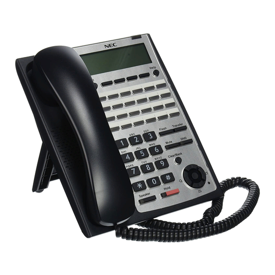
ISSUE 6.0 SL1100 5 INSTALLING THE MULTILINE TELEPHONES AND ECTION OPTIONAL TERMINALS 5.1 Installing the Multiline Telephones There are three types of Multiline Telephones available in the SL1100 system. • IP4WW-12TXH-B-TEL • IP4WW-24TXH-B-TEL • IP4WW-24TIXH-C-TEL (IP) 5.1.1 Location of Controls Handset... -
Page 112: Multiline Telephone Legs Adjustment
SL1100 ISSUE 6.0 Functions 12TXH 24TXH 24TIXH Backlit Dial Pad Incoming LED 2 colors (Red/Green) Connected to Digital Extension Port Ethernet Port on the Network Headset Port Power Feeding AC Adapter (DC27 V,1 A) or PoE (IEEE802.3af) 5.1.2 Multiline Telephone Legs Adjustment The Multiline Telephone provides adjustable legs for angling the phone to best suit each user. -
Page 113: Figure 2-110 Setting For High Position
ISSUE 6.0 SL1100 5.1.2.2 High position setting Turn telephone over (button side down). Pull up the Leg Stoppers. Leg Stopper Figure 2-110 Setting for High Position Adjust the leg to desired height. < High position > Figure 2-111 Leg Setting for High Position Lead the Line and Handset cords through the applicable grooves. -
Page 114: Wall-Mounting The Multiline Telephone
SL1100 ISSUE 6.0 5.1.3 Wall-Mounting the Multiline Telephone Arrange the cables and put down the leg as shown below. Handset cord Telephone line cord < Bottom view> Figure 2-112 Cabling for Wall-Mount For IP4WW-24TIXH-C only: When wall-mounting the IP4WW-24TIXH-C, attach the IP4WW-WALL MOUNT UNIT to the bottom panel as shown. -
Page 115: Figure 2-114 Hook-Switch Hanger
ISSUE 6.0 SL1100 Remove the switch-hook from the unit. Turn the tab toward the top. Then slide the hook-switch into position. Refer to Figure 2-114 Hook-Switch Hanger on page 2-81. Hook-switch hanger Hook-switch hanger Figure 2-114 Hook-Switch Hanger Install two screws into a wall. The screw heads must be remained about 3 mm (0.12″). -
Page 116: Install The Ip Multiline Telephone (Ip4Ww-24Tixh-C1 Tel)
SL1100 ISSUE 6.0 5.2 Install the IP Multiline Telephone (IP4WW-24TIXH-C1 TEL) 5.2.1 System Connection The IP Multiline Telephone is connected via HUB. IP Multiline Telephone Exit Help LAN Cable (10BASE-T/100BASE-TX) Flash Transfer Mute PQRS WXYZ Clear/Back Speaker Hold Ferrite Core... -
Page 117: Applying Power To The Ip Multiline Telephone
ISSUE 6.0 SL1100 5.2.3 Applying Power to the IP Multiline Telephone IP Multiline Telephone (IP4WW-24TIXH-C1) supports two different power sources for the Telephone. • AC-LE UNIT Plug the Optional AC-[ ] AC adapter input jack in the telephone base unit, and plug the 2-prong wall plug of the AC adapter in AC outlet. -
Page 118: Figure 2-120 Cabling Of Dss
SL1100 ISSUE 6.0 Lead the Line cord through the applicable grooves. Figure 2-120 Cabling of DSS 5.3.1.2 High position setting Turn DSS Console over (button side down). Pull up the Leg Stoppers. Leg Stopper Figure 2-121 Leg Stopper of DSS Console... -
Page 119: Wall-Mounting The Dss Console
ISSUE 6.0 SL1100 Adjust the leg to desired height. < High position > Figure 2-122 High Position Setting Lead the Line cord through the applicable grooves. (Refer to Figure 2-120 Cabling of DSS on page 2-84) 5.3.2 Wall-Mounting the DSS Console Lift the leg and lead the cable through the applicable grooves. -
Page 120: Installing The Headset
SL1100 ISSUE 6.0 Install two screws into a wall. The screw heads must be remained about 3 mm (0.12″). 3 - 4 mm 1 - 3 mm (0.12″ - 0.16″) (0.04″ - 0.12″) 83.5 mm (3.287″) 7 - 9.5 mm (0.28″... -
Page 121: Installing The Doorphone Box
ISSUE 6.0 SL1100 Connect the Headset cord into the Headset socket. Headset socket < Bottom view> Figure 2-126 Headset Socket (2-wire Multiline Telephone) Headset socket PC(X) LAN(=) AN(=) < Bottom view> Figure 2-127 Headset Socket (IP Multiline Telephone) The headset configuration is assigned using system programming. -
Page 122: Figure 2-128 Doorphone Box And Bracket
SL1100 ISSUE 6.0 Connect the cable to the screw terminals on the Doorphone box. (No polarity sensitive) Wall-mount bracket Upper housing Screw terminals Screw Connect cable Figure 2-128 Doorphone Box and Bracket Mount the Wall-Mount bracket on the wall using supplied screws. -
Page 123: Connecting The Doorphone
ISSUE 6.0 SL1100 5.5.2 Connecting the Doorphone J421 J103 J431 J411 J102 J101 RY1/2 SLI 9-12 /DPH 1-2 Port 1 Port 2 Port 3 Port 4 T : Tip R : Ring Modular Cable (2-wire, Straight) Doorphone Figure 2-130 Connecting the Doorphone The Doorphone configuration is assigned using system programming. -
Page 124: Table 2-28 Rj-61 General Purpose/Door Unlock Relay Control Connector (J7)
SL1100 ISSUE 6.0 J7 (RJ61) 8 765 4321 RY1/2 Door unlock control devices Figure 2-131 Connecting the Door Unlock Device The following table shows the pin-outs for the RJ-61 cable connector. Table 2-28 RJ-61 General Purpose/Door Unlock Relay Control Connector (J7) Pin No. -
Page 125: Installing The External Paging Speaker/External Moh/Bgm Sources
ISSUE 6.0 SL1100 5.7 Installing the External Paging Speaker/External MOH/BGM Sources 5.7.1 Connecting the Audio Equipment • The audio jack labeled PAGE, MOH, BGM can be used for audio port (External paging, External MOH, BGM) • Audio port configuration is assigned using system programming. -
Page 126: Bgm/External Moh Source Input Specifications
SL1100 ISSUE 6.0 5.7.3 BGM/External MOH Source Input Specifications Table 2-31 BGM/External MOH Source Input Specifications Item Specification Input Impedance 600 Ω @ 1 kHz Input Level Nominal 250 mV (-10 dBm) Maximum Input 1 V RMS 5.8 SMDR (Station Message Detail Recording) 5.8.1 General... - Page 127 • Installation of the WHA must be done by your NEC dealer. • Disconnect the telephone line cord from its wall jack. • Plug the cord from the cordless headset base unit into the SL1100 headset socket. • Plug the AC Adapter cord into the cordless headset base unit.
-
Page 128: Figure 2-134 Headset Socket (2-Wire Multiline Telephone)
SL1100 ISSUE 6.0 5.9.1.3 Connecting to the Headset System Base To connect your telephone to the Headset System Base: Plug the cord into the telephone's headset socket and the socket on the Headset System base. Insert the Headset Adapter plug into the lifter jack on the Headset System base. -
Page 129: Operation
Refer to the Plantronics User Guide for additional details. 5.9.3 General Notes • The WHA is compatible with all SL1100 telephones: - 12/24-Button Digital Telephones (BE110269/ BE110270/BE110271/BE110272) - 24-Button IP Telephones (BE110277/BE110278) • A “HEADSET” key does not need to be programmed on the SL1100 Telephone. -
Page 130: Installing The Dt330 Terminals And Options (V4.0 Or Higher)
Refer to www.plantronics.com for details. The SL1100 Telephone must be equipped with the NEC WHA (Wireless Headset Adapter – P/N BE113158). 5.10 Installing the DT330 terminals and options (V4.0 or higher) 5.10.1 Connecting the DT330 terminals and options to the system Refer to SV8100 System H/W Manual for installing DT330 digital multiline terminals. -
Page 131: Chapter 3 System Start Up
System Start Up 1 SYSTEM START UP ECTION 1.1 Before Starting Up the System Before starting up the system, make sure: • KSU(s) are installed correctly. • All extensions are cabled correctly. • All earth ground and PSTN Trunks are cabled correctly. •... -
Page 132: Perform A Cold Start
SL1100 ISSUE 6.0 1.2.1 Perform a Cold Start This section describes the process for starting the system for the first time or starting a system that requires the customer data be deleted. System software is loaded from flash memory, and the customer data is deleted from RAM memory. -
Page 133: Perform A Hot Start
ISSUE 6.0 SL1100 Turn the power switch ON at the Main KSU. Continue holding the LOAD button (S1) for approximately three seconds or until Status LED (D5) starts flashing red. RUN LED LED (D5) < Front view > Figure 3-4 Status LED (D5) and RUN LED Location Release the LOAD button. -
Page 134: Section 2 Programming Mode
Base Service OP1 OP2 Figure 3-7 Entering Programming Mode Display 2 For the details of programming, refer to the SL1100 Programming Manual. (separate issue) 2.2 Exiting the Programming Mode Press Mute key several times to return to the "Program Mode" Screen. -
Page 135: Saving (Backup) The Customer Data
ISSUE 6.0 SL1100 2.3 Saving (Backup) the Customer Data When the installer/system administrator exits from the programming mode, the system will automatically save the customer data to the on-board memory which is backed up by lithium battery. Additionally, the customer data can be saved to a CF Card for backup purpose. The PZ-VM21 daughter board must be installed to the CPU card with a BLANK CF card inserted. -
Page 136: Figure 3-10 Inserting The Cf Card
SL1100 ISSUE 6.0 For the details of PZ-VM21 daughter board installation, refer to Installing the PZ-VM21 PCB on page 2-72. Turn the power off, insert the Customer Data CF card into the CF Slot on PZ-VM21. CPU card CF Slot (CN2) -
Page 137: Section 3 System Shut Down
ISSUE 6.0 SL1100 3 SYSTEM SHUT DOWN ECTION 3.1 Powering Off the System Turn the all KSU(s) power off using the power switch. Figure 3-16 Power Switch Location • If Expansion KSU(s) are installed, turn the power on/off in the order of Expansion 2 KSU, Expansion 1 KSU and then Main KSU. - Page 138 SL1100 ISSUE 6.0 MEMO System Start Up...
-
Page 139: Chapter 4 Maintenance
Maintenance 1 FUSE REPLACEMENT ECTION 1.1 Replacing the Fuse This fuse is only for external battery box connection, it is not used for AC power to the system. If Expansion KSU(s) are installed, turn the power on/off in the order of Expansion 2 KSU, Expansion 1 KSU and then Main KSU. -
Page 140: Figure 4-2 Removing The Main-Cover
SL1100 ISSUE 6.0 Loosen two screws and remove the Main-Cover. Main-Cover Two screws Hooks Figure 4-2 Removing the Main-Cover Exchange the fuse (250 V/8 A) on 084M-B1 PCB. 084M-B1 FUSE (8 A / 250 V) < Top View > Figure 4-3 Exchanging the Fuse... -
Page 141: Figure 4-4 Replacing The Main-Cover
ISSUE 6.0 SL1100 Replace the Main-Cover and fasten two screws. Main-Cover Two screws Hooks Figure 4-4 Replacing the Main-Cover Hardware Manual... -
Page 142: Section 2 Lithium Battery Replacement
Before replacing the Lithium battery, make sure which type of Lithium battery is required and prepare the new Lithium battery. (CR2032) NEC recommends that a backup of the customer data is performed before powering off the system (either PCPro file or CF card backup) in order to replace the backup battery. -
Page 143: Replacing The Lithium Battery
ISSUE 6.0 SL1100 2.3 Replacing the Lithium Battery Remove the Sub-Cover at the Main KSU. Sub-Cover Figure 4-6 Removing the Sub-Cover Power off the system, and remove the AC plug from the AC outlet. Disconnect the AC power cord from the KSU. -
Page 144: Figure 4-8 Removing The Main-Cover
SL1100 ISSUE 6.0 Loosen two screws and remove the Main-Cover. Main-Cover Two screws Hooks Figure 4-8 Removing the Main-Cover Press tab A and lift the CPU support bracket. Remove CPU card from the Main KSU. CPU card CPU support 084M-B1 at 1228M KSU... -
Page 145: Figure 4-10 Location Of Lithium Battery Socket
ISSUE 6.0 SL1100 Refer to following figure for the Lithium battery location on the CPU card. CPU card Battery socket < Conductor side > Figure 4-10 Location of Lithium Battery Socket Remove the old Lithium battery and insert the new one into the socket. -
Page 146: Figure 4-13 Installing The Cpu Card
SL1100 ISSUE 6.0 Reinstall the CPU card into the 084M-B1 mother board and close the CPU support bracket. CPU card CPU support 084M-B1 at 1228M KSU Figure 4-13 Installing the CPU Card 10. Replace the Main-Cover and Sub-Cover. Maintenance... -
Page 147: Section 3 Main Software Upgrading
• Prepare the CF Card (32MB, or upwards and formatting by FAT(16)), and store the new main software on the CF card by PC. (New main system software is supplied by NEC.) • Install the PZ-VM21 PCB. (if the system does not have it.) 3.3 Main Software Version Confirmation... -
Page 148: Upgrading The Main Software
SL1100 ISSUE 6.0 Press Enter Key (Navigation Key) to show the main system software version and Hardware Key Code. VERSION: 01.00 MAC: 00-60-B9-D8-DF-8E HKEY: 2810-0000-0000 Off-Hook and return to Time & Date mode. 11-10 WED 1:49PM Menu Dir VM:00 CL:00 3.4 Upgrading the Main Software... -
Page 149: Figure 4-16 Removing The Main-Cover
ISSUE 6.0 SL1100 Loosen two screws and remove the Main-Cover. Main-Cover Two screws Hooks Figure 4-16 Removing the Main-Cover Insert the CF card (with the new main system software loaded) to the CF slot on PZ-VM21 daughter board. (PZ-VM21 should be temporary installed if not already fitted.) -
Page 150: Table 4-1 Status Leds
SL1100 ISSUE 6.0 Push in and hold the LOAD button (S1 on the CPU card). CPU card Sub-Cover < Front view > Figure 4-18 LOAD Button (S1) Location Turn the system power on. Continue holding the LOAD button (S1) for approximately 10 seconds or until Status LED (D5) starts flashing red. - Page 151 ISSUE 6.0 SL1100 13. When the system has completed reloading the software, the RUN LED (D1) will flash blue. • To confirm the new software version number, press the Navigation key on any display telephone to view the system version number see Main Software Version Confirmation on page 4-9.
-
Page 152: Section 4 Led Indications
SL1100 ISSUE 6.0 4 LED INDICATIONS ECTION The LEDs on the CPU indicate the following: • RUN (D1) = The CPU is operating (Blue) • D2, and D3 = Alarms (Red) • D4 = Flash access indication (Red) • D5 = Boot status (Red) •... -
Page 153: Section 1 System Capacity
Specifications 1 SYSTEM CAPACITY ECTION Table 5-1 System Capacity Items 1 KSU 2 KSU 3 KSU Description Note (1228) (2456) (3684) Expansion Slot System Maximum Port 1KSU: 084M+PRI+080E+4COIDBx2 2KSU: (084M+PRI +080E)x2+4COIDBx4 3KSU: 084Mx3+PRIx2+080Ex4+4COIDBx7 Trunk Port Max. 1KSU: PRIx1+4COIDB/BRIx2 2KSU: PRIx2+4COIDB/BRIx4 3KSU: PRIx2+4COIDB/BRIx7 Trunk Port Analog... -
Page 154: Specifications
SL1100 ISSUE 6.0 Items 1 KSU 2 KSU 3 KSU Description Note (1228) (2456) (3684) Station Port 2W Key Set Max. 24/KSU 084M+080Ex2 DTL-12/24D-1 Max.16/KSU (V4.0 Added) P TEL DTL-12BT-1P Max.6/KSU (V4.0 Added) SLT (–28V) 1KSU: 084M+008Ex2 2KSU: 084Mx2+008Ex6 3KSU: 084Mx3+008Ex9... - Page 155 ISSUE 6.0 SL1100 Items 1 KSU 2 KSU 3 KSU Description Note (1228) (2456) (3684) DSP Sender Hardware Manual...
-
Page 156: Section 2 System Specifications
SL1100 ISSUE 6.0 2 SYSTEM SPECIFICATIONS ECTION 2.1 General Precautions • Never attempt to insert wires, pins, etc. into the vents or other holes of the equipment. • Do not use benzene, thinner, or the like, or any abrasive powder to clean the equipment. Wipe it with a soft cloth. -
Page 157: Electrical Specifications
ISSUE 6.0 SL1100 110VAC 120VAC 220VAC 230VAC 240VAC Input Voltage (Rated Voltage) 90 VAC to 264 VAC (100VAC/120VAC/220VAC/230VAC/240VAC) Frequency 47 Hz - 63 Hz (Rated Frequency: 50/60 Hz) Phase and Wire Single Phase, 2 Line + PE Type Ground Requirement No.14 AWG Copper Wire...(Ksu) -
Page 158: Traffic Capacity
SL1100 ISSUE 6.0 2.8 Traffic Capacity Traffic Capacity Basic System Package Expanded System Package Traffic Capacity 2540 BHCA 2540 BHCA 2540 Busy-Hour Call Attempts (BHCA) is based on a Full Capacity. 2.9 IP Terminal Power Chart Table 5-5 IP Terminal Power Chart... -
Page 159: Optional Unit Mechanical Specifications
ISSUE 6.0 SL1100 Equipment Width Depth Height Weight Note DTL-12BT-1P TEL 183 mm 258 mm 109 mm 1.3 kg (V4.0 Added) (7.6 in) (10.16 in) (4.29 in) (45.6 oz) 2.13 Optional Unit Mechanical Specifications Table 5-8 Optional Unit Mechanical Specifications... -
Page 160: External Paging Output Specifications
SL1100 ISSUE 6.0 Item Specification Rated Current DC 320 mA Maximum Contact Normally Open 2.16 External Paging Output Specifications Table 5-11 External Paging Output Specifications Item Specification Output Impedance 600 Ω @ 1 kHz Output Level Nominal 250 mV (-10 dBm) -
Page 161: Cabling Requirements
ISSUE 6.0 SL1100 2.20 Cabling Requirements • Do not run extension cable in parallel with the AC source, telex or computer etc. If the cables are near cable runs to those devices, use shielded cable with grounded shields or install the cable in conduit. - Page 162 SL1100 ISSUE 6.0 MEMO 5-10 Specifications...
- Page 163 ISSUE 6.0 SL1100 MEMO Hardware Manual 5-11...
- Page 164 Hardware Manual NEC Corporation ISSUE 6.0...