Table of Contents
Advertisement
Advertisement
Table of Contents

Summary of Contents for Canon EOS C700
- Page 1 PUB. DIE-0494-000 Digital Cinema Camera Instruction Manual...
- Page 2 For more information about the recycling of this product, please contact your local city office, waste authority, approved scheme or your household waste disposal service or visit www.canon-europe.com/weee, or www.canon-europe.com/battery. CAN ICES-3(A)/NMB-3(A) WARNING This is a class A product.
- Page 3 Trademark Acknowledgements • SD, SDHC and SDXC Logos are trademarks of SD-3C, LLC. • Canon is an authorized licensee of the CFast 2.0™ trademark, which may be registered in various jurisdictions. • Microsoft and Windows are trademarks or registered trademarks of Microsoft Corporation in the United States and/or other countries.
- Page 4 Highlights of the Camera The Canon Digital Cinema Camera EOS C700 / EOS C700 PL / EOS C700 GS PL has been designed to meet the demanding needs and highest expectations of industry professionals. The following are just some of the many features that will help turn your creative vision into reality.
- Page 5 C700 series Software for aiding production workflow camera (A 140). Canon XF Utility (A 158) lets you copy the XF-AVC • Improved clip name format with more information clips you recorded from your recording media to a for easier identification and organization of clips computer, play back the clips and organize them.
-
Page 6: Table Of Contents
Table of Contents 1. Introduction 11 Preparing Recording Media 48 Compatible Recording Media 48 About this Manual 11 Inserting a CFast Card 49 Conventions Used in this Manual 11 Removing a CFast card 49 Supplied Accessories 12 Inserting and Removing an SD Card 50 Names of Parts 13 Initializing Recording Media 51 Microphone Holder 18... - Page 7 Recording 117 Displaying Zebra Patterns 99 Using Metadata 118 Using the False Color Display 100 Setting a User Memo Created with Canon XF Setting the Time Code 101 Utility 118 Selecting the Time Code Mode 101 Entering Information About the Recording 119...
- Page 8 4. Customization 127 6. External Connections 149 Assignable Buttons and Customizable USER Video Output Configuration 149 Screen 127 Main Recording Video Configuration and Video Changing the Assigned Function and Using an Output Configuration from Assignable Button 127 the SDI OUT Terminals 149 Assignable Functions 128 Main Recording Video Configuration and Video Customizing and Using the USER Screen 130...
- Page 9 IP Streaming 178 Preparations 178 Streaming Video over IP 179 FTP File Transfer 181 Preparations 181 Transferring Clips (FTP Transfer) 182 8. Additional Information 183 Setup Screens and Menu Options 183 Setup screens 183 Camera Menu and Monitoring Menu 186 Displaying the INFO Screens 198 Troubleshooting 201 List of Messages 206...
-
Page 11: Introduction
About this Manual Thank you for purchasing the Canon EOS C700 / EOS C700 PL / EOS C700 GS PL. Please read this manual carefully before you use the camera and retain it for future reference. Should the camera fail to operate correctly,... -
Page 12: Supplied Accessories
Used to secure the optional WFT-E6 or WFT-E8 Wireless File Transmitter or optional GP-E1 GPS Receiver when it is attached to the camera. Used to secure the CDX-36150 Codex Recorder for Canon EOS C700 when it is docked with the camera. -
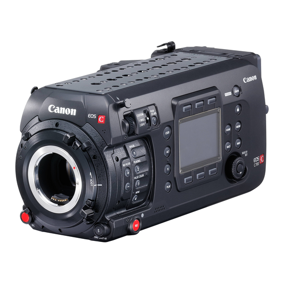
Page 13: Names Of Parts
Names of Parts Names of Parts 9 * 10 * 11 * 12 * 13 14 * 15 * 16 * 17 * 18 * 21 * 22 * 12 * 23 * 24 25 * * Illuminated buttons (A 194). 1 MAGN. - Page 14 Names of Parts 5 6 7 9 10 11 12 13 14 15 17 18 1 D-TAP terminal (A 28) 13 SD card slot cover switch (A 50) 2 Cable clamp 14 SD CARD access indicator (A 50) 3 Exhaust ventilation outlet (A 64) 15 CFast (CFast card slot A) and CFast (CFast...
- Page 15 Names of Parts Z EF lens mount with Cinema Lock (A 44) [] PL lens mount (A 46) 1 MIC (microphone) terminal (A 109) 8 EF lens mount index (A 44) 2 VIDEO terminal (A 41) 9 Lens mount handles For connecting the optional EVF-V70 OLED 10 Built-in monaural microphone (A 110) Electronic Viewfinder.
- Page 16 Names of Parts (with the supplied battery adapter attached to the camera) MON. 1 MON. 2 GENLOCK/ SYNC OUT TIME CODE IN/OUT HDMI 10 1112 (with no extension module attached to the camera) 1 V-mount battery plate (A 26) 12 SDI OUT terminals: from top to bottom SDI OUT 1 2 V-shaped battery mount (V-mount) to SDI OUT 4 (A 149, 152) 3 Battery release latch (A 26)
- Page 17 Names of Parts 1 Tape measure hooks and focal plane marks 5 Socket for the extension unit attachment bracket Use the hooks to accurately measure the distance (A 120, 160) from the focal plane. 6 Battery adapter release switch (A 23, 24) 2 Screw holes for 1/4"-20 mounting screws (10 mm 7 Battery adapter’s fixation screws (2 on the top (0.39 in.) deep)
-
Page 18: Microphone Holder
Names of Parts Microphone Holder (A 109) 1 Microphone lock screw 4 Hex socket head fixation bolts (0.64 cm, 2 Microphone holder 1/4"; 2 in total) 3 Microphone cable clamp 5 Through-holes for fixation bolts Handle Unit (A 40) * One more in the same location on the opposite side. 1 Screw holes for 1/4"-20 mounting screws 3 Hex socket head fixation bolts (10 mm (0.39 in.) deep, 9 in total) -
Page 19: Clamp Base
Names of Parts Clamp Base (A 41) 1 Slider for an optional viewfinder’s clamp rail 3 Hex socket head fixation bolts (0.64 cm, 1/4"; 2 Clamp rail locking screw 4 in total) -
Page 20: Evf-V70 Oled Electronic Viewfinder (Optional)
Names of Parts EVF-V70 OLED Electronic Viewfinder (optional) (A 41) 2 * 3 * 9 * 10 11 * Illuminated buttons (A 194). 1 FUNC (main functions) button (A 73)/ 9 FALSE COLOR button (A 100)/ Assignable button EVF 1 (A 127) Assignable button EVF 4 (A 127) 2 EVF (open the monitoring menu) button (A 33, 10 Swing arm locking screw (A 41) -
Page 21: 4K Workflow Overview
After recording RAW data, you can develop the RAW data using the Cinema RAW Development software (A 158) to generate full-quality data. Using the Canon RAW Plugin, you can work with RAW recordings directly from supported NLE applications. -
Page 22: Color Grading With The Aces Workflow
4K Workflow Overview Color Grading with the ACES Workflow Post-production CDX-36150 OpenEXR Recorder data (ACES 1.0) Extension Cinema RAW Color grading module 4K recording Development connector (RAW) ASC- (docking) Input External Transform SDI OUT terminals Recorder MON. or HDMI OUT output ACES proxy... -
Page 23: Preparations
Preparations Preparing the Backup Battery The camera uses a CR2025 lithium button battery as a backup battery to ensure that the camera’s settings are not lost when no other power source is connected to the camera. To install the supplied lithium button battery, you will need to remove any extension modules attached to the camera*. -
Page 24: Inserting The Lithium Button Battery
Preparing the Backup Battery Inserting the Lithium Button Battery The camera features a built-in backup battery so the camera settings are not lost while you replace the lithium button battery. 1 Make sure no power supply is connected to the DC IN 12V terminal. - Page 25 Preparing the Backup Battery 4 Push down the locking lever until it clicks. 5 Using the supplied hex wrench, attach the four fixation screws to the top and bottom of the battery adapter to secure it in place.
-
Page 26: Preparing The Main Power Supply
Preparing the Main Power Supply Preparing the Main Power Supply You can power the camera using a commercially available V-mount battery or the DC IN 12V terminal. Even when a battery is attached, if a power source is connected to the DC IN 12V terminal, the camera will not draw power from the battery. -
Page 27: Using The Dc In 12V Terminal
Preparing the Main Power Supply Using the DC IN 12V Terminal 1 Press the Q button to turn off the camera. 2 Connect the 4-pin XLR connector of the external power supply to the camera’s DC IN 12V terminal. IMPORTANT •... -
Page 28: Power Outputs
Preparing the Main Power Supply Power Outputs The camera features three power outputs for accessories: the DC OUT 24V 2A terminal, the DC OUT 12V 2A terminal and the D-TAP terminal on the battery adapter. Power output Specifications* DC OUT 24V 2A terminal Fischer 3-pin connector, 24 V DC, 2.0 A (max.) DC OUT 12V 2A terminal LEMO 2-pin connector, 12 V DC, 2.0 A (max.) -
Page 29: Date, Time And Language Settings
Date, Time and Language Settings Date, Time and Language Settings Setting the Date and Time You will need to set the date and time on the camera before you can start using it. When you turn on the camera for the first time or after the camera’s settings were reset, the [Date/Time] screen will appear automatically on the control display with the time zone selected so you can set the camera’s internal clock. -
Page 30: Changing Camera Settings With The Screen Buttons
Changing Camera Settings with the Screen Buttons Changing Camera Settings with the Screen Buttons There are three basic ways to change the various camera settings: Using the screens that appear on the camera’s control display and the screen buttons, using the camera menu displayed on the control display, and using the monitoring menu displayed on monitoring devices along with the camera’s image. - Page 31 Changing Camera Settings with the Screen Buttons Following is a step-by-step example of how to change a setting using the screen buttons. In the manual, these will be abbreviated in most cases. For example, the instruction below stands for the procedure following it. [SHUTTER] >...
-
Page 32: Using The Menus
Using the Menus Using the Menus You can change the camera’s settings using the camera menu displayed on the control display or the monitoring menu displayed on the screen of connected monitoring devices. You can also register frequently used menu settings in 6 customized submenus (My Menu 1 to 3 that can be set up independently for the camera menu and the monitoring menu) (A 35). -
Page 33: Selecting An Option From The Monitoring Menu
Using the Menus 4 Turn the SELECT dial to select the desired setting option and then press SET. • Depending on the menu item, additional selections may be necessary. 5 Press the HOME button to close the menu and return to the HOME screen. Selecting an Option from the Monitoring Menu The monitoring menu appears on the screen of external monitors connected to one of the camera’s MON. - Page 34 Using the Menus • The orange selection frame will appear on a menu item in the submenu. • Press the BACK button to return to the previous submenu. 4 Push the joystick up/down or turn the SELECT dial to select the desired menu item (in the example [Language •...
-
Page 35: Using The Customized Submenu (My Menu)
Using the Menus Using the Customized Submenu (My Menu) You can register up to 15 frequently used menu settings under a My Menu submenu for easy access. You can save up to 6 separate sets of My Menu settings (3 each for the camera menu and monitoring menu) so you can customize different options for different shooting situations. - Page 36 Using the Menus Resetting the My Menu Submenu 1 Reset all the menu settings registered to the currently selected My Menu set. [My Menu]* > [Edit] > [Reset All] * In the monitoring menu, the icon and submenu name will reflect the My Menu set currently selected. By default this is [My Menu 1] ( 2 Camera menu: Press both [RESET] buttons simultaneously.
- Page 37 Using the Menus Using the keyboard screen Monitoring menu keyboard Camera menu keyboard Current text length/Character limit 1 Turn the SELECT dial (camera menu) or push the joystick in any direction (monitoring menu) to select a character and press SET to add it to the text. •...
-
Page 38: Preparing The Camera
Wireless File Transmitter/ Handle unit* GP-E1 GPS Receiver Clamp base* UN-5 or UN-10 Unit Cables CDX-36150 Codex Recorder for Canon EOS C700** MO-4E or MO-4P B4 Mount Adapter UC-V75 or UC-V1000 Remote Operation Unit Cable V-Mount Batteries/ AC Adapters (commercially available) - Page 39 Codex • For details about docking the CDX-36150 Recorder with the camera and using it to record, refer to Recorder – Guide for the EOS C700 models (separate PDF file).
-
Page 40: Attaching The Handle Unit
Preparing the Camera Attaching the Handle Unit You can adjust the position of the handle considering the total weight and center of gravity of the camera with the lens and all the accessories used attached. Attach the handle unit to the desired position on top of the camera. -
Page 41: Using The Optional Evf-V70 Oled Electronic Viewfinder
Preparing the Camera Using the Optional EVF-V70 OLED Electronic Viewfinder After attaching the supplied clamp base to the camera, you can attach the optional EVF-V70 OLED Electronic Viewfinder to the clamp base. An optional UN-5 or UN-10 Unit Cable is required to connect the optional viewfinder to the camera. - Page 42 • By default, the optional viewfinder’s screen will be dimmed automatically when it is not being used. You can [Eye Sensor] to [Off] to keep the optional viewfinder’s screen always bright. • When using one of the Canon Log gamma curves, you can apply a LUT to the image displayed on the optional viewfinder (A 154).
-
Page 43: Attaching The Microphone Holder
Preparing the Camera Removing the Optional Viewfinder 1 Press the button to turn off the camera. 2 Disconnect the unit cable from the camera and viewfinder. 3 Remove the end cap from the clamp rail’s arm attached to the clamp base and loosen the clamp rail locking screw. 4 While pulling out the locking pin at the other side of the clamp rail, remove the clamp rail from the clamp base. -
Page 44: Preparing The Lens
Preparing the Camera Preparing the Lens As much as possible, attach and remove the lens quickly and in a clean environment free of dust. Refer also to the instruction manual of the lens used. IMPORTANT • Make sure to turn off the camera before attaching/removing a lens and before connecting/disconnecting a lens’s 12-pin interface cable to/from the camera’s LENS terminal. - Page 45 EF lenses, visit your local Canon Web site. 1 Download the lens firmware update file from the Canon Web site and save it on an SD card. Insert the SD card containing the lens firmware update into the SD card slot.
- Page 46 Preparing the Camera IMPORTANT • Be sure to observe the following precautions while the lens firmware is being updated. Failing to do so can cause malfunctions. - Do not remove the power source or turn off the camera. - Do not remove the lens. - Do not operate any buttons or controls on the camera.
-
Page 47: In-Camera Lens Correction
• If correction data is not available, or if the broadcast lens attached is not compatible with L.C.A.C., the corresponding menu option will appear grayed out. In the case of an EF lens, visit your local Canon Web site and check if there is correction data available for the lens you are using. If so, download the necessary update package and upgrade the camera’s firmware following the instructions supplied therein. -
Page 48: Preparing Recording Media
Initialize recording media (A 51) when you use them with this camera for the first time. * The SD card is used also to save custom picture files, menu settings files and user memo files created with the Canon XF Utility software (A 158) for later use on the camera. -
Page 49: Inserting A Cfast Card
Preparing Recording Media Inserting a CFast Card You can insert a CFast card into CFast card slot A or slot B. If you have two CFast cards, you can use both slots. 1 Slide the CFast card slot cover switch in the direction of the arrow. -
Page 50: Inserting And Removing An Sd Card
Preparing Recording Media IMPORTANT • Observe the following precautions while a CFast card access indicator is illuminated in red. Failure to do so may result in permanent data loss. - Do not remove the power source or turn off the camera. - Do not open the cover of the CFast card slot being accessed. -
Page 51: Initializing Recording Media
Preparing Recording Media Initializing Recording Media The first time you use a recording media with this camera, initialize it first. You can also initialize a recording media to permanently delete all the data it contains. When initializing an SD card, you can select quick initialization, which clears the file allocation table but does not physically erase the stored data, or complete initialization, which deletes all data completely. -
Page 52: Switching Between The Cfast Card Slots
Preparing Recording Media Switching Between the CFast Card Slots The camera features two CFast card slots, CFast (CFast card slot A) and CFast (CFast card slot B). If both slots contain a CFast card, you can switch between them as necessary. Press the SLOT SEL. -
Page 53: Checking The Remaining Recording Time On Recording Media
Preparing Recording Media Checking the Remaining Recording Time on Recording Media The recording media icons and the approximate remaining recording time* (in minutes) on each card are displayed on the HOME screen and at the bottom left of the monitoring screen. Additionally, on the [MEDIA] screen (A 200), you can check the total space, used space, and remaining recording time* on each recording media. -
Page 54: Adjusting The Black Balance
Adjusting the Black Balance Adjusting the Black Balance You can have the camera adjust the black balance automatically when the ambient temperature changes considerably or if there is a noticeable change in a true black video signal. 1 Attach the body cap to the lens mount. •... -
Page 55: Recording
Recording Recording Video This section explains the basics of recording clips*. Before making important recordings for the first time, make test recordings using the video configuration(s) you plan to use to check that the camera operates correctly. Troubleshooting Should the camera fail to operate correctly, refer to (A 201). - Page 56 - Do not open the card slot cover of the card being accessed and do not remove the card. - Do not remove the power source or turn off the camera. • Be sure to save your recordings regularly (A 158), especially after making important recordings. Canon shall not be liable for any loss or corruption of data.
-
Page 57: Onscreen Displays On The Home Screen
000.00°, 1/0000, 000.00Hz Shutter speed (A 74) 000000, 00.0 dB ISO speed/Gain (A 76) Canon Log 3, Canon Log 2, Canon Log, [Gamma] setting in the custom picture file (A 134) Wide DR, Normal 1 to Normal 4 C.Gamut, BT.2020, DCI-P3, BT.709 [Color Space] setting in the custom picture file (A 134) , 0000±0... - Page 58 Recording Video Icon/Display Description Recording media status for the main recording ([Main]) and sub recording ([Sub]) and 0000 min, Recording media: in green – can record; in white – reading the recording media; in yellow – the Ð SDI-OUT RAW recording media is almost full.
-
Page 59: Onscreen Displays On The Shooting Screen
Recording Video Onscreen Displays on the Shooting Screen Refer to this section for an explanation of the various onscreen displays that appear on the shooting screen that is displayed on monitoring devices (optional viewfinder or external monitors). You can use the custom display function ( 139) to turn off individual onscreen displays if they are not required. - Page 60 Recording Video Left side of the screen Icon/Display Description Custom Display 0000 mm Approximate focal length of the lens 1: [Focal Length] Key lock (A 56) 1: [Key Lock] Network connection status (A 165) 2: [Network Functions] GPS signal (A 120): continuously on - satellite signal acquired; flashing - satellite 2: [GPS] signal not acquired.
- Page 61 Recording Video Icon/Display Description Custom Display DC IN 00.0V, Power supply voltage (DC IN and battery) (A 26) 2: [DC IN / Battery] BATT 00.0V Ð • The power source currently in use is indicated with a mark. A to Z Camera index (A 62) 2: [Camera Index] Exposure bar (A 82)
-
Page 62: Setting The Clip File Name
Recording Video NOTES NOTES [Monitoring Setup] > [Surrounding Area] settings to show on the monitoring • You can use the screen more of the periphery around the area that is actually recorded by the camera. [Monitoring Setup] > [OSD Output] > [VIDEO] or [MON.+HDMI] > [Peripheral •... -
Page 63: Using The Fan
[Rec/Media Setup] (3) > [Metadata] > [User Defined] 2 Set the desired text/number using the keyboard screen (A 37). • Camera menu only: Press [RESET] to reset the user-defined field to [CANON]. Using the Fan The camera uses an internal cooling fan to reduce the camera’s internal heat. In shooting mode, you can change the fan’s operation mode and speed. - Page 64 Recording Video Setting the Fan Speed in Playback Mode 1 Press the PLAY button to open the playback control screen. 2 Open the [Fan Speed] submenu. [System Setup] (B) > [Fan Speed] 3 Select the desired fan speed and then press SET. IMPORTANT •...
-
Page 65: Video Configuration: Video Format, System
(A 71). For available video configurations when using a CDX-36150 Recorder docked with the camera, refer to Codex Recorder - Guide for the EOS C700 models (separate PDF file). For available video configurations when using an external recorder connected to one of the SDI OUT terminals, refer Video Output Configuration (A 149). -
Page 66: Selecting The Bit Rate
Video Configuration: Video Format, System Frequency, Frame Rate, Resolution and Bit Rate Selecting the Bit Rate 1 Open the [Bit Rate] submenu. [Rec/Media Setup] (3) > [Bit Rate] [S&F FPS] > [OPTIONS] > [Bit Rate]. • Alternatively, using the HOME screen: 2 Select the desired option and then press SET. - Page 67 Video Configuration: Video Format, System Frequency, Frame Rate, Resolution and Bit Rate Available video configuration settings (ProRes) System frequency/Frame rate Resolution, codec and color sampling 59.94 Hz 50.00 Hz 24.00 Hz 59.94P 29.97P 23.98P 50.00P 25.00P 24.00P 4096x2160 Ü Ü Ü...
-
Page 68: Slow & Fast Motion Recording
Slow & Fast Motion Recording Slow & Fast Motion Recording The camera can record using a progressive frame rate (shooting frame rate) that is different from the playback frame rate. Recording a clip at a higher frame rate than the [Frame Rate] setting will result in a slow motion effect during playback (up to 1/10 of the original speed). - Page 69 Slow & Fast Motion Recording Video configuration Shooting frame rate (fps) Frame rate Vertical resolution Color sampling 2160 YCbCr 4:2:2, 10 bit 1.00, 5.00, 15.00, 25.00, 26.00, 28.00, 30.00, 34.00, 38.00, 42.00, 46.00, RGB 4:4:4, 10 bit, 50.00 RGB 4:4:4, 12 bit 1080 25.00P 1.00, 5.00, 15.00, 25.00, 26.00, 28.00, 30.00, 34.00, 38.00, 42.00, 46.00,...
- Page 70 Slow & Fast Motion Recording 1 Open the slow & fast motion selection screen/submenu. [S&F FPS] > [ACTIVATE] Home screen: [Rec/Media Setup] (3) > [Slow & Fast Motion] Monitoring menu: 2 Select [On] or [On (crop)] and then press SET. •...
-
Page 71: Simultaneous Sub Recordings
4 Select the desired option and then press SET. For XF-AVC Proxy sub recordings ([SD Card]) only, when using one of the Canon Log gamma curves: 3 To apply a LUT to the XF-AVC Proxy clips, open the LUT selection screen. - Page 72 Simultaneous Sub Recordings 4 Select the desired LUT and then press SET. 5 Press the REC button to start and stop recording. • The sub recording clip will be recorded on the CFast or SD card simultaneously with the main recording. IMPORTANT •...
-
Page 73: Changing Main Camera Functions With The Func Button
Changing Main Camera Functions with the FUNC Button Changing Main Camera Functions with the FUNC Button With the direct setting mode you can adjust the following main functions using the optional viewfinder’s FUNC button or an assignable button set to [FUNC] while checking the effect on the image on a monitoring device. This section will explain the basic operation of the direct setting mode with the optional viewfinder. -
Page 74: Shutter Speed
Shutter Speed Shutter Speed Set the shutter speed based on the recording conditions. For example, you may want to set slower shutter speeds in darker environments. The camera offers the following modes. You can also perform this function remotely using Browser Remote on a connected network device (A 166, 172). -
Page 75: Changing The Shutter Speed Mode And Value
Shutter Speed Changing the Shutter Speed Mode and Value 1 Open the shutter speed [Mode] submenu. [SHUTTER] > [OPTIONS] > [Mode] HOME screen: [Camera Setup] (v) > [Shutter] > [Mode] Monitoring menu: 2 Select the desired mode and then press SET. •... -
Page 76: Iso Speed/Gain
[Gamma] setting in the custom picture file (A 134) Model and other conditions [Canon Log] or [Wide DR] [Canon Log 2] or [Canon Log 3] ISO 400 / 6 dB ISO 800 / 12 dB ] condition set... -
Page 77: Changing The Iso Speed Or Gain Value
ISO Speed/Gain Changing the ISO Speed or Gain Value 1 Open the ISO speed/gain [Select] submenu. [ISO/GAIN] > [OPTIONS] > [Select] HOME screen: [Camera Setup] (v) > [ISO/Gain] > [Select] Monitoring menu: 2 Select [ISO] or [Gain] and then press SET. 3 From the same submenu, select [ISO Increment] or [Gain Increment] to select the adjustment increment to use when adjusting the ISO speed or gain, respectively. -
Page 78: Nd Filter
ND Filter ND Filter Using the ND filter allows you to open up the aperture to obtain a shallower depth of field even when recording in bright surroundings. You can also use the ND filter to avoid the soft focus caused by diffraction when using small apertures. -
Page 79: Adjusting The Aperture
Adjusting the Aperture Adjusting the Aperture You can affect the brightness of your recordings or change the depth of field by adjusting the aperture. By default, the camera is set to manual aperture but, depending on the lens used, the camera offers 3 ways to adjust the aperture. -
Page 80: Manual Aperture
Adjusting the Aperture Manual Aperture With the control dial on the left side of the camera you can adjust the aperture value of a compatible lens using the smallest iris increment allowed by the lens. The function of the control dial is determined by the position of the CUSTOM switch next to it. -
Page 81: Momentary Automatic Aperture - Push Auto Iris
Adjusting the Aperture • When using a compatible EF Cinema lens, you can change the displays to T values instead of F values with [IRIS] > [OPTIONS] > [Iris Indicator] setting. • The aperture value (F value or T value) displayed on the screen may differ from the indication on the lens’s aperture scale. -
Page 82: Exposure Compensation - Ae Shift
Adjusting the Aperture NOTES NOTES • Automatic aperture is not available when slow & fast motion recording is activated. • The aperture value may change in the following cases. - While using the built-in extender or iris compensation function of an EF Cinema lens, when you switch from automatic aperture to manual aperture. - Page 83 Adjusting the Aperture Options [Backlight]: Suitable when recording backlit scenes. [Standard]: Averages the light metered from the entire screen, giving more weight to the subject in the center. [Spotlight]: Use this option when recording a scene in which only a certain part of the picture is lit, for example, when the subject is lit by a spotlight.
-
Page 84: Gamma Curve And Main Color Settings
- There are also other LUTs available that can be applied for processing in post-production. For the latest information on available LUTs, please visit your local Canon Web site. - Page 85 Gamma Curve and Main Color Settings 1 Open the custom picture file’s selection screen. [COLOR] > [CP OTHERS] > [File] > [Select] HOME screen: [Custom Picture] (/) > [File] > [Select] Monitoring menu: 2 Turn the SELECT dial to select the desired file and then press [OK] (HOME screen) or press SET (monitoring menu).
-
Page 86: White Balance
White Balance White Balance The camera uses an electronic white balance process to calibrate the picture and produce accurate colors under different lighting conditions. There are 4 methods of setting the white balance. You can also perform this function remotely using Browser Remote on a connected network device (A 166, 171). -
Page 87: Auto White Balance (Awb)
White Balance Auto White Balance (AWB) The camera constantly adjusts the white balance automatically to achieve an optimal level. The camera will adjust the white balance if the light source changes. 1 Select the [ AWB] setting and press SET (A 86). •... -
Page 88: Adjusting The Color Temperature Or Cc Value
White Balance Adjusting the Color Temperature or CC Value 1 Select a white balance setting other than [ AWB] (A 86). 2 Press [ADJUST]. • The current color temperature value and CC value appear on the control display. The color temperature will be marked with an orange selection frame. -
Page 89: Adjusting The Focus
Adjusting the Focus Adjusting the Focus Depending on the lens used, the camera offers several ways to focus and incorporates Dual Pixel CMOS AF technology for advanced autofocus performance. For a list of compatible lenses and functions that can be used, refer to the appendix (A 221). -
Page 90: Manual Focus
Adjusting the Focus Manual Focus Focus manually using the focus ring on the lens. You can also perform this function remotely using Browser Remote on a connected network device (A 166, 173). The autofocus mode is set to [One Shot] by default. If you need to change the setting, start the procedure from the beginning. - Page 91 Adjusting the Focus • Press [CENTER] (setup screen) or press the BACK button on the optional viewfinder to return the frame to the center position. 3 You can also display a second frame around a different subject. Setup screen: From the [Focus Assistance Functions] screen in step 1, [OPTIONS] > [Focus Guide] > [Display 2nd Frame] >...
-
Page 92: Z One-Shot Af
Adjusting the Focus Magnification 1 Press the MAGN. button. [F. ASSIST.] > [MAGN.] to turn the magnification on and off. From the • Alternatively, you can press [Assist. Functions] (A) > [Magnification] > [VIDEO Output] and monitoring menu you can use the [MON.+HDMI Output] settings to turn the magnification on and off separately on the optional viewfinder or on external monitors. -
Page 93: Z Af-Boosted Mf
Adjusting the Focus 5 Press and hold the ONE-SHOT AF button. • A white AF frame will appear on the monitoring screen and the camera will focus automatically. When you are using Face AF, the face detection frame around the face of the person who has been determined to be the main subject will turn white. - Page 94 - When an ISO speed or gain value in the extended range is selected (A 76). - When the [Gamma] setting in the custom picture file (A 134) is set to one of the Canon Log settings or [Wide DR].
-
Page 95: Z Changing The Af Frame Size And Position
Adjusting the Focus AF Lock While using continuous AF or AF-Boosted MF, you can lock the focus on a certain subject and then move the camera to change the composition. [AF] > [AF LOCK]. While the autofocus is active, press •... -
Page 96: Z Face Detection
Adjusting the Focus Z Face Detection When the face detection function is activated, the camera will detect people’s faces. When there are a number of people in the picture, one person will be determined to be the main subject but you have the option to select a different person as the main subject. -
Page 97: Z Tracking A Specific Subject
Adjusting the Focus NOTES NOTES • In certain cases, faces may not be detected correctly. Typical examples include: - Faces extremely small, large, dark or bright in relation to the frame. - Faces that are turned to the side, at a diagonal, partially hidden or upside-down. •... -
Page 98: Onscreen Markers, Zebra Patterns And False Color
Onscreen Markers, Zebra Patterns and False Color Onscreen Markers, Zebra Patterns and False Color Using onscreen markers allows you to make sure your subject is correctly framed and is within the appropriate safe area. The zebra patterns help you identify areas that are overexposed. The false color display allows you to check if the exposure is correct. -
Page 99: Displaying Zebra Patterns
Onscreen Markers, Zebra Patterns and False Color To set the aspect ratio 1 Select [Aspect Ratio], select the desired option and then press SET. • If you selected one of the preset aspect ratios, the rest of the procedure is not necessary. If you selected [Custom], continue the procedure to set the desired aspect ratio. -
Page 100: Using The False Color Display
Onscreen Markers, Zebra Patterns and False Color Using the False Color Display The false color display is an assistance display mode that turns the image from the camera to black and white and overlays on it 6 different colors to indicate important brightness ranges. Press the FALSE COLOR button on the camera to turn on the false color display on external monitors connected to the MON. -
Page 101: Setting The Time Code
Setting the Time Code Setting the Time Code In shooting mode, the camera generates a time code signal and records it with the recorded clips. The time code signal can be output from the SDI OUT terminals, MON. terminals and TIME CODE IN/OUT terminal. In playback mode, the time code embedded in the clip being played back can be output from the SDI OUT terminals and MON. -
Page 102: Selecting Drop Or Non-Drop Frame
Setting the Time Code Setting the Time Code’s Initial Value If you set the time code mode to [Preset], you can set the initial value of the time code. 1 Open the time code setting screen. Setup screen: [SET TC] [System Setup] (B) >... - Page 103 Setting the Time Code NOTES NOTES • The frames value of the time code runs from 0 to 23 (frame rate set to 23.98P or 24.00P), from 0 to 24 (frame rate set to 25.00P, 50.00i or 50.00P), or from 0 to 29 (all other frame rates). •...
-
Page 104: Setting The User Bit
Setting the User Bit Setting the User Bit The user bit display can be selected from the date or the time of recording, or an identification code consisting of 8 characters in the hexadecimal system. There are sixteen possible characters: the numbers 0 to 9 and the letters A to F. -
Page 105: Synchronizing With An External Device
Synchronizing with an External Device Synchronizing with an External Device Using Genlock synchronization, you can synchronize this camera’s video signal to that of an external video device. Similarly, using an external time code signal, you can synchronize this camera’s time code to the external signal. -
Page 106: Reference Video Signal Input (Genlock Synchronization)
Synchronizing with an External Device Reference Video Signal Input (Genlock Synchronization) When a reference sync signal (tri-level HD signal or analog blackburst) is input through the GENLOCK/ SYNC OUT terminal, the phases of the camera’s V and H sync will automatically be synchronized to it. The phase difference between the external Genlock signal and the camera is initially set to 0. -
Page 107: Reference Video Signal Output
Synchronizing with an External Device • When the camera locks on an external time code signal, [E] will appear next to the time code on the control display and at the bottom right corner of the monitoring screen. • If the external time code signal is incorrect or there is no input signal, the internal time code set in the camera will be recorded instead. -
Page 108: Recording Audio
Recording Audio Recording Audio The camera features 4-channel linear PCM (24 bit, 48 kHz) audio recording and playback. You can record audio using the INPUT terminals (commercially available microphones, analog line-in audio sources, AES/EBU digital audio sources), the MIC terminal (commercially available microphones) or the built-in monaural microphone*. The audio signal will be output with the video signal from the SDI OUT terminals, MON. -
Page 109: Connecting An External Microphone Or External Audio Input Source To The Camera
Recording Audio Audio input selection Recorded audio channels/audio sources switches [CH1/2 IN]* [CH3/4 IN]* [CH2 Input]** for INPUT 1 for INPUT 2 [INPUT Built-in microphone Built-in microphone [Monaural Mic] ANALOG – [INPUT 2] INPUT 1 terminal INPUT 2 terminal Terminals] (mono) (mono) [INPUT... -
Page 110: Setting The Audio Input Type For The Input 1/Input 2 Terminals
Recording Audio Cable clamp INPUT 1 terminal INPUT 2 terminal MIC terminal About the monaural microphone The monaural microphone allows you to add comments while shooting, which can be synchronized to the audio and video during editing. Monaural microphone NOTES NOTES •... -
Page 111: Selecting The Audio Input Source For Audio Channels
Recording Audio IMPORTANT • When connecting an analog microphone or device that does not support phantom power, make sure to set the corresponding INPUT switch to MIC or LINE, respectively. If you set the switch to MIC+48V, the microphone or device may be damaged. Selecting the Audio Input Source for Audio Channels You can select the audio input source that will be recorded on CH1/CH2 or CH3/CH4, independently for each pair of audio channels. -
Page 112: Additional Settings For External Analog Microphones
Recording Audio 2 Select automatic or manual audio level adjustment. Setup screen: Press [A M] to switch between A (automatic) and M (manual) adjustment mode. Monitoring menu: Select [Automatic] or [Manual] and then press SET. • If you selected automatic audio level, the rest of the procedure is not necessary. •... -
Page 113: Monitoring The Audio With Headphones
Recording Audio Microphone Attenuator (INPUT Terminals) When the audio input selection switch for INPUT 1 or INPUT 2 is set to ANALOG and the corresponding ANALOG (analog source selection) switch is set to MIC or MIC+48V, you can activate the external microphone’s attenuator (20 dB). -
Page 114: Colors Bars/Audio Reference Signal
Colors Bars/Audio Reference Signal Colors Bars/Audio Reference Signal You can have the camera generate color bars and a 1 kHz audio reference signal and output them from the VIDEO terminal (optional viewfinder, color bars only), SDI OUT terminals, MON. terminals, HDMI OUT terminal and ×... -
Page 115: Waveform Monitor
Waveform Monitor Waveform Monitor The camera can display a simplified waveform monitor on the monitoring screen. You can select one of 6 types of monitors and also adjust the waveform amplification. Displaying the Waveform Monitor Press the WFM button. • The waveform monitor window will appear at the right of the monitoring screen on external monitors connected to one of the MON. - Page 116 Waveform Monitor NOTES NOTES • The waveform monitor will not be affected even if a LUT is applied to the video output. • The waveform monitor cannot be displayed while magnification is activated. • If the [Knee] settings in the custom picture file (A 135) were changed, a horizontal line will appear on the waveform monitor indicating the luminance (Y) level corresponding to the knee point.
-
Page 117: Adding An $ Mark Or % Mark While Recording
Adding an $ Mark or % Mark while Recording Adding an $ Mark or % Mark while Recording After making an important recording, you can add an OK mark ($) or check mark (%) to the clip (XF-AVC clips on the CFast card only) to flag it and set it apart. You can use the $ mark to protect important clips, as clips with an $ mark cannot be deleted using the camera. -
Page 118: Using Metadata
Setting a User Memo Created with Canon XF Utility Before you can add a user memo, you must first download and install Canon XF Utility (A 158). Next, create the user memo and then save it to an SD card. Once you insert the SD card in the camera and select the user memo, it will be added to clips you record. -
Page 119: Entering Information About The Recording
Using Metadata Entering Information About the Recording You can enter scene and take information to help identify the recording later on. 1 Open the [Scene] or [Take] submenu. [Rec/Media Setup] > [Metadata] > [Scene] or [Take] Camera menu: [Rec/Media Setup] (3) > [Metadata] > [Scene] or [Take] > [Set]* Monitoring menu: * To clear the scene/take information, select [Reset] instead. -
Page 120: Recording Gps Information (Geotagging)
GPS information (latitude, longitude and altitude) as part of the metadata of XF-AVC clips (A 118). Later, the GPS information can be used to organize and search clips using Canon XF Utility (A 158). For details about attaching and configuring the receiver, refer to the GP-E1’s instruction manual. - Page 121 Recording GPS Information (Geotagging) NOTES NOTES [System Setup] > [GPS] > [Display Info] setting to display the information • You can use the received from the GPS signal. • After replacing the power source or when first turning on the camera, it may take longer for the GPS receiver to start receiving the GPS signal.
-
Page 122: Using Anamorphic Lenses
Using Anamorphic Lenses Using Anamorphic Lenses You can attach an anamorphic lens to the camera and set the anamorphic desqueeze ratio used to display the image from the camera on monitoring devices while shooting or during playback. 1 Open the [Anamorphic] submenu. [Monitoring Setup] (¢) >... -
Page 123: Using The Optional Rc-V100 Remote Controller
Using the Optional RC-V100 Remote Controller Using the Optional RC-V100 Remote Controller You can connect the optional RC-V100 Remote Controller to the camera’s REMOTE A terminal or REMOTE B terminal in order to control the camera (including advanced recording functions) from a distance. In addition to turning the camera on and off and navigating the menu, you can control various shooting related functions such as aperture and shutter speed, and custom picture settings like knee and sharpness. - Page 124 Remote Cable, check the serial number of the RC-V100. If the serial number starts with “01 xxxx” (where xxxx represents other digits), you will need to update the remote controller’s firmware. Canon will perform this feature upgrade, and requires that the remote controller be sent to an accredited Canon Service Center.
-
Page 125: Taking Photos
Taking Photos Taking Photos You can take photos when the camera is in record standby mode. Photos are saved onto the SD card and their size depends on the video configuration currently in use. Resolution Photo size Approximate file size per image 4096x2160, 2048x1080 2048x1080 930 KB... - Page 126 Taking Photos Understanding folder names • An example folder name is “101_1103”. The first 3 digits indicate the folder number (from 100 to 999) and the last 4 digits indicate the month and day when the folder was created. In the example, the folder numbered 101 was created on November 3.
-
Page 127: Customization
Customization Assignable Buttons and Customizable USER Screen The camera offers a number of physical buttons to which you can assign various functions (assignable buttons). Additionally, the control display offers the USER screen that you can customize by assigning various functions to each of the 6 screen buttons. -
Page 128: Assignable Functions
Assignable Buttons and Customizable USER Screen 2 Select the desired function and then press SET. • The selected function will be assigned to the selected button. • If you selected one of the preset functions, the rest of the procedure is not necessary. If you selected [User Setting], the menu’s title bar will change to blue to indicate you are selecting a menu setting to register. - Page 129 Assignable Buttons and Customizable USER Screen Function name Description [False Color] Turns the false color display on/off. [False Color: VIDEO], Turns the false color display on/off on the optional viewfinder (VIDEO) or on all external monitors [False Color: MON.+HDMI] connected to the MON. terminals or HDMI OUT terminal, respectively. [False Color: MON.1], Turns the false color display on/off on an individual external monitor connected to the respective [False Color: MON.2],...
-
Page 130: Customizing And Using The User Screen
Assignable Buttons and Customizable USER Screen Function name Description 3, 4 [Shutter] Enters the direct setting mode with the shutter speed underlined and ready to be adjusted. Enters the direct setting mode with the ISO speed or gain value underlined and ready to be 3, 4 [ISO/Gain] adjusted. -
Page 131: Custom Picture Settings
Custom Picture Settings Custom Picture Settings The camera lets you change many settings (A 134) that control various aspects of the image produced. As a set, all these settings are treated as a single custom picture file. After adjusting the desired settings to your preference, you can save up to 20 custom picture files (in the camera or on an SD card), and load them later to apply exactly the same settings (A 133). -
Page 132: Resetting Custom Picture Files
Custom Picture Settings 3 Press the BACK button. 4 Enable the editing of the custom picture file’s detailed settings. HOME screen: [CP OTHERS] > [Other Settings] > [Activate] > [On] Monitoring menu: [Other Settings] > [Activate] > [On] 5 From the same submenu select a detailed setting you wish to adjust and then press SET. 6 Change the setting to the desired level and then press SET. -
Page 133: Copying Custom Picture Files
Custom Picture Settings Copying Custom Picture Files You can transfer custom picture files between the camera and SD card. Copying a File from the Camera to an SD Card 1 Select a custom picture file (A 131). 2 Open the [Copy to 8] submenu. [COLOR] >... -
Page 134: Available Custom Picture Settings
[Preset] [Canon Log 3 : C.Gamut], [Canon Log 3 : BT.2020], [Canon Log 3 : DCI-P3], [Canon Log 3 : BT.709], [Canon Log 2 : C.Gamut], [Canon Log 2 : BT.2020], [Canon Log 2 : DCI-P3], [Canon Log 2 : BT.709], [Canon Log], [BT.2020], [BT.709], [Off]... -
Page 135: Other Settings
These settings control the lower part of the gamma curve (dark areas of the image). When [Gamma] [Level] is set to one of the Canon Log settings or [Wide DR], these settings have no effect on the picture. [Level]: Raises or lowers the lower part of the gamma curve. - Page 136 0 (no slope), 1 (steep slope) to 3 (gradual slope) (1) These settings allow you to adjust the sharpness of only the areas above the knee point. When [Gamma] is set to one of the Canon Log settings or [Wide DR], these settings have no effect on the picture.
- Page 137 Custom Picture Settings Submenu levels / Menu items Options / Additional information [Level Depend Slope] 0 (no slope), 1 (steep slope) to 3 (gradual slope) (0) Determines the slope of the area between the upper and lower parts of the gamma curve. [Level Depend Offset] 0 to 50 (0) Adjusts the sharpness level of dark areas in the image.
- Page 138 –50 to 50 (±0) Adjusts the black level set by the [Black] > [Master Pedestal] setting. When [Gamma] is set to one of the Canon Log settings, this setting has no effect on the picture. [Over 100%] [Through], [Press], [Clip] Determines how the camera handles video signals exceeding 100%.
-
Page 139: Customizing Onscreen Displays
Customizing Onscreen Displays Customizing Onscreen Displays You can use the [Custom Display 1] or [Custom Display 2] settings to customize the onscreen displays that appear on the monitoring in shooting mode and the [Custom Display] settings to customize the onscreen displays that appear during playback. -
Page 140: Saving And Loading Camera Settings
Saving and Loading Camera Settings Saving and Loading Camera Settings After you adjust settings in the various menus and setup screens, you can save those settings in the camera or on an SD card. You can load those settings at a later date or on another C700 / C700 PL / C700 GS PL camera so that you can use that camera in the exact same way. -
Page 141: Playback
Playback Playback This section explains how to play back clips and photos with the camera. For details on playing back clips using Connecting to an External Monitor or Recorder an external monitor, refer to (A 152). The PLAY (Playback Control) Screen Press the PLAY button to switch the camera to playback mode. -
Page 142: Selecting The Recording Media And Format To Play Back
Playback 1 [PB MEDIA] (playback media): Press the screen 9 [OPTIONS]: Press the screen button to open the button to select the media and format selected clip operations (or photo operations) menu for playback (A 142). (A 145). 2 Media/format selected for playback 10 Recording media selected for playback 3 Playback operation: Ý... - Page 143 Playback IMPORTANT • Observe the following precautions while an access indicator is illuminated in red. Failure to do so may result in permanent data loss. - Do not remove the power source or turn off the camera. - Do not open the card slot cover of the card being accessed and do not remove the card. Adjusting the Volume You can connect headphones to the ×...
-
Page 144: Onscreen Displays During Playback
Playback Onscreen Displays During Playback If the output of onscreen displays is activated for the terminal used (A 155), the following onscreen displays will appear on the monitoring screen during playback, along with the playback image. 1 Temperature warning and fan operation (A 64) 10 Clip number / Total number of clips 2 Recording media 11 Onscreen displays output (A 155) -
Page 145: Clip/Photo Operations
Clip/Photo Operations Clip/Photo Operations Using the clip operations menu, you can perform various operations on the clip selected in the PLAY screen or display additional information about the clip. Available options will depend on the format selected for playback. The only operation available for photos is [Delete] (A 147) so the following table will show only the clip operations. -
Page 146: Adding And Deleting $ Marks Or % Marks
Clip/Photo Operations 1 Recording date and time 2 Clip file name (A 62) 3 Bit rate and compression (A 66) 4 Frame rate* (A 65) 5 Clip geotagged with GPS information** (A 120, 176) 6 Relay clip** (A 52) 5 indicates the first part of the recording, 6 indicates the middle part(s) and 7 indicates the last part. -
Page 147: Deleting Clips And Photos
Clip/Photo Operations Deleting $ Marks or % Marks 1 Select the desired clip (A 142). • In the clip list select a clip with an $ or % mark. 2 Delete the clip mark ($ or % mark). [OPTIONS] > [Delete $ Mark] or [Delete % Mark] > [OK] •... -
Page 148: Copying A Custom Picture File Embedded In A Clip
Clip/Photo Operations Copying a Custom Picture File Embedded in a Clip You can copy to the camera the custom picture file embedded in an XF-AVC clip. 1 Select the desired clip (A 142). 2 Review the custom picture settings embedded with the clip. [OPTIONS] >... -
Page 149: External Connections
External Connections Video Output Configuration The video signal output from the SDI OUT terminals, MON. terminals and HDMI OUT terminal, depends on the clip’s video configuration) and on various menu settings. Refer to the following tables for the video output configuration from each terminal, depending on the main recording video configuration used. -
Page 150: Main Recording Video Configuration And Video Output Configuration From The Mon. Terminals And Hdmi Out Terminal
Video Output Configuration Main Recording Video Configuration and Video Output Configuration from the MON. Terminals and HDMI OUT Terminal Recording video configuration Video output configuration 3, 5 MON. terminals HDMI OUT terminal [Main Rec Format] [MON. Output] [HDMI Max Res.] Frame rate Resolution [2048x1080/... -
Page 151: Playback Video Configuration And Video Output Configuration By Terminal
Video Output Configuration Playback Video Configuration and Video Output Configuration by Terminal Refer to the following tables for the video output configuration from each terminal, depending on the video configuration of the clip being played back. Video configuration of the clip Video output configuration MON. -
Page 152: Connecting To An External Monitor Or Recorder
Connecting to an External Monitor or Recorder Connecting to an External Monitor or Recorder When you connect the camera to an external device, be it a monitor (to monitor the recording or for playback) or an external video recorder (for recording), use the terminal on the camera that matches the one you wish to use on the external device. -
Page 153: Using The Mon. Terminals
Connecting to an External Monitor or Recorder [Rec/Media Setup] > [Rec Command] to [On] to use the camera’s REC button to • You can set control also the recording operation of an external recorder connected to the SDI OUT terminals and MON. terminals. -
Page 154: Applying A Lut To Video Outputs
– – – – – [COLOR] > [CP MAIN] > [Preset] is set to [Canon Log 2 : C.Gamut] or [Canon Log 3 : C.Gamut]. * Only when 1 Open the LUT selection submenu. [COLOR] > [LUT] HOME screen: [Monitoring Setup] (¢) > [LUT] Monitoring menu: 2 Select the desired terminal and then press SET. -
Page 155: Superimposing Onscreen Displays On Video Outputs
Connecting to an External Monitor or Recorder Options Output Settings with LUT applied Applied LUT Description Gamma curve Color space LUT for viewing on the optional viewfinder and external monitors compatible with BT.709 [BT.709] Wide DR BT.709 specifications. LUT for viewing on external monitors compatible with ITU-R BT.2020 standards, which [BT.2020] Wide DR BT.2020... - Page 156 Connecting to an External Monitor or Recorder NOTES • When the HDMI OUT terminal's resolution is set to 4096x2160 or 3840x2160, the camera’s onscreen displays will not be displayed on the monitor connected to the HDMI OUT terminal.
-
Page 157: Audio Output
Audio Output Audio Output The camera can output audio from the SDI OUT terminals, MON. terminals, HDMI OUT teminal or × (headphone) terminal. The audio signal recorded with main recording clips recorded in the camera is 4-channel linear PCM audio, 24 bit. The number of audio channels output and the audio bit depth depend on the terminal used and other settings. -
Page 158: Working With Clips On A Computer
Saving Clips to a Computer You can use Canon XF Utility to save and organize clips on a computer and the Canon XF plugins to easily use the clips directly from major non-linear editing (NLE) applications. The software and plugins are available as free downloads from your local Canon Web site. -
Page 159: Network Functions
• Data transmitted over networks is not encrypted. • Canon shall not be liable for any loss of data or damage resulting from incorrect network configuration or settings. Additionally, Canon shall not be liable for any loss or damage caused by the use of network functions. -
Page 160: Connecting To A Wi-Fi Network
Connecting to a Wi-Fi Network Connecting to a Wi-Fi Network Attaching the Optional Wireless File Transmitter Turn off the camera and attach the optional WFT-E6 or WFT-E8 Wireless File Transmitter (hereafter, simply “wireless transmitter”) to the camera’s system extension terminal. 1 Press the button to turn off the camera. -
Page 161: Camera Access Point
Connecting to a Wi-Fi Network Camera Access Point In this mode the camera itself serves as a wireless access point to which other Wi-Fi-enabled devices can connect. Initially, basic settings for a Camera Access Point connection are configured in the camera and you can use the default settings to connect immediately to the camera. -
Page 162: Wi-Fi Protected Setup (Wps)
Connecting to a Wi-Fi Network 3 Select [Infrastructure] and then press SET. 4 Select the desired method to configure the access mode. [Wi-Fi Setup Method] > desired method > press SET • Continue the setup with the procedure corresponding to the method you wish to use (see the reference pages below). -
Page 163: Searching For Access Points
Connecting to a Wi-Fi Network Searching for Access Points The camera will automatically detect access points in the vicinity. After you select the desired access point, you only need to enter the selected network’s password to connect the camera. For details about the access point’s network name (SSID) and password refer to the wireless router’s instruction manual or consult the network administrator in charge of the access point. -
Page 164: Connecting To A Wired (Ethernet) Network
Connecting to a Wired (Ethernet) Network Connecting to a Wired (Ethernet) Network Connect the camera to a router or other device connected to a wired (Ethernet) network using a commercially available Ethernet cable. Use Category 5e, shielded twisted pair (STP) Ethernet cables compatible with Gigabit Ethernet (1000BASE-T) and with good shielding capability. -
Page 165: Checking The Network's Status And Settings
Checking the Network’s Status and Settings Checking the Network’s Status and Settings After activating a network function, the camera will connect to the network that was configured in advance. The icons displayed on the control display and at the top left of the monitoring screen will indicate the type of network selected and the connection status. -
Page 166: Browser Remote: Controlling The Camera From A Network Device
On the Browser Remote screen, you can also check the remaining recording time on the recording media, power source levels and the camera’s time code. * For details about compatible devices, operating systems, Web browsers, etc., please visit your local Canon Web site. ** XF-AVC clips only. -
Page 167: Starting Browser Remote
* A Web browser that supports JavaScript and is enabled to accept cookies is required. ** For details about compatible devices, operating systems, Web browsers, etc., please visit your local Canon Web site. Preparations on the camera 1 Activate Browser Remote on the camera. - Page 168 Browser Remote: Controlling the Camera from a Network Device 3 Enter the camera’s URL exactly as shown on the Browser Remote information screen. 4 Enter the user name and password. • Be sure to log in with the user name and password of one of the users that were set on the camera (A 166).
-
Page 169: Using Browser Remote
Browser Remote: Controlling the Camera from a Network Device NOTES NOTES • The live view image will not be displayed in Browser Remote in the following cases. - While color bars are displayed on the camera. - When magnification is activated while recording. •... - Page 170 Browser Remote: Controlling the Camera from a Network Device 1 Live view screen Shows the camera’s live view image. When the live view image is not turned on, the camera ID and lens information will appear here. 2 Status indicators Wi-Fi connection indicator.
- Page 171 Browser Remote: Controlling the Camera from a Network Device 12 Current camera settings This panel displays an overview of the camera settings currently used. You can change camera settings with the controls in the detailed camera settings panel (14) on the right. [ND]: ND filter [WB]: White balance [ISO]/[Gain]: ISO speed or gain value...
- Page 172 Browser Remote: Controlling the Camera from a Network Device To change exposure related settings Touch the [Exposure] tab in the detailed camera settings panel. 1 ND Filter buttons • To use the extended ND range options (8 or 10 stops), touch [Extended Range].
- Page 173 Browser Remote: Controlling the Camera from a Network Device To adjust the focus and use focus-related functions Touch the [Focus] tab in the detailed camera settings panel. To use the following functions, make sure that the focus mode on the lens is set to automatic (A 89).
- Page 174 Browser Remote: Controlling the Camera from a Network Device Z AF-Boosted MF 1 Touch the AF mode button and select [AF-Boosted MF]. • When the focus is in the manual adjustment range, a yellow focus frame will appear on the live view screen. •...
- Page 175 Browser Remote: Controlling the Camera from a Network Device 2 Touch the live view screen to select the subject you wish to track. • A tracking frame will appear on the live view screen and the camera will track the subject as it moves. •...
- Page 176 Browser Remote: Controlling the Camera from a Network Device The Metadata Screen [ * [Full]/[Meta] users only. Using Browser Remote you can create, edit and transfer to the camera a metadata profile that can be embedded with the recorded XF-AVC clips. This metadata profile includes the user memo information (clip title, Using Metadata creator, location and description), as well as GPS information.
- Page 177 Browser Remote: Controlling the Camera from a Network Device 8 Status indicators See the descriptions in the section about the [v] screen (A 170). Activate] button Touch the button to give priority to the metadata entered in this screen when recording XF-AVC clips. This overrides the metadata read from a file saved on the SD card.
-
Page 178: Ip Streaming
* Only 2 channels. When recording main recording clips with 4 audio channels, you can select which two channels to stream over ** This can be a dedicated video transfer device or decoder software on a computer. For details about compatible decoders, please visit your local Canon Web site. Configuration of video streamed over IP... -
Page 179: Streaming Video Over Ip
IP Streaming • Setup screen only: Press [RESET] to reset the port number to [5000]. • Using the default port is recommended. Options [UDP]: This protocol prioritizes transfer speeds but does not guarantee the reliability/integrity of the data. Lost or delayed IP packets are ignored. [RTP]: Standard protocol for video/audio broadcasts over the Internet. - Page 180 IP Streaming 3 Activate IP streaming on the camera. [NETWORK] > [IP Streaming] > [ACTIVATE] (set it to [On]) Setup screen: [System Setup] (B) > [Network Settings] > [IP Streaming] > [Activate] > [On] Monitoring menu: • and the connection type icon will appear on the HOME screen and at the top left of the monitoring screen.
-
Page 181: Ftp File Transfer
FTP File Transfer FTP File Transfer You can transfer sub recording clips (XF-AVC Proxy) from the camera to another device connected to the network, using the FTP protocol. The following explanations assume that the FTP server is on, ready and correctly configured. Preparations Before you can transfer XF-AVC Proxy clips to a connected device, you need to configure the FTP server settings and other settings related to the handling of folders and files. -
Page 182: Transferring Clips (Ftp Transfer)
FTP File Transfer Transferring Clips (FTP Transfer) After connecting the camera to a network (Wi-Fi (Infrastructure) or wired (Ethernet)), you can transfer to the FTP server, XF-AVC Proxy clips recorded on the SD card. 1 Open the PLAY screen for sub recordings (XF-AVC Proxy) on the SD card. [PB MEDIA] >... -
Page 183: Additional Information
Additional Information Setup Screens and Menu Options Using the Menus For details about how to select an item, refer to (A 32). For details about each function, see the reference page. Setting options in boldface indicate default values. Depending on the camera’s operating mode and the settings, some menu items may not be available. Such menu items do not appear or appear grayed out in menu screens. - Page 184 Setup Screens and Menu Options Screen button commands Setting options and additional information [ISO/GAIN] Select the ISO speed or gain value. (A 76) [OPTIONS] [Select], [Extended Range], [ISO Increment], [Gain Increment] See the corresponding settings under [ISO/Gain] in the table for the [Camera Setup] (v) menu (A 186).
- Page 185 Setup Screens and Menu Options Screen button commands Setting options and additional information [F. ASSIST.] Focus adjustment with the SELECT dial. Z[FACE] (face detection) [On], [Off] Turn the face detection function on/off (A 96). [MAGN.] (magnification) [On], [Off] Turn the magnification function on/off (A 92). [PEAKING] [On], [Off] Turn the peaking function on/off (A 91).
-
Page 186: Camera Menu And Monitoring Menu
Setup Screens and Menu Options Screen button commands Setting options and additional information [OPTIONS] [Mode], [Run], [DF/NDF], [TC In/Out] See the corresponding settings under [Time Code] in the table for the [System Setup] (B) menu (A 193). PLAY screen Information about the clip/photo selected for playback and playback related functions (A Screen button commands Setting options and additional information [PB MEDIA]... - Page 187 Setup Screens and Menu Options Submenu levels / Menu items Setting options and additional information [Extended ND Range]** [On], [Off] (A 78) [Shutter]** (A 74) [Mode] [Speed], [Angle], [Clear Scan], [Slow], [Off] [Shutter Increment] [1/3 stop], [1/4 stop] [White Balance]** [Shockless WB] [On], [Off] (A 86)
- Page 188 Setup Screens and Menu Options [Audio Setup] menu (¡) (monitoring menu only) Submenu levels / Menu items Setting options and additional information [Audio Input] [Select CH1/CH2 Input], [INPUT Terminals], [MIC Terminal], [Monaural Mic] (A 111) [Select CH3/CH4 Input] [Audio Rec Level CH1] to [Automatic], [Manual] (A 111) [Audio Rec Level CH4],...
- Page 189 (A 62) [Reel Number], [Clip Number] [001] to [999] (A 62) [User Defined] User defined string up to 5 characters ([CANON]) (A 62) [Scene], [Take] Scene description up to 16 characters / Take description up to 8 characters (A 119) [Lens Squeeze] [x2.0], [x1.3], [Off]...
- Page 190 Setup Screens and Menu Options [Monitoring Setup] (¢) menu Submenu levels / Menu items Setting options and additional information [Control Display] (A 31) [Camera] [Brightness] 1 to 5 (3) [Turn Off Display] [Assignable Buttons], [Auto (Remote OU-700)] [Remote OU-700] [Brightness] 1 to 5 (3) [EVF-V70]* (A 42)
- Page 191 Setup Screens and Menu Options Submenu levels / Menu items Setting options and additional information [Displayed Units] [Meters], [Feet]** Changes the distance units used in camera displays between meters and feet. [Custom Display 1] (A 139) [Light Metering], [On], [Off] [Custom Picture], [Focal Length], [ND Filter], [Focus Mode], [Key Lock], [White Balance],...
- Page 192 Setup Screens and Menu Options Submenu levels / Menu items Setting options and additional information [Gain] [Off], 1 to 15 (8) [Frequency] 1 to 4 (2) [Peaking 2] [Color] [White], [Red], [Yellow], [Blue] [Gain] [Off], 1 to 15 (15) [Frequency] 1 to 4 (1) [Focus Assist.
- Page 193 Setup Screens and Menu Options [System Setup] (B) menu Submenu levels / Menu items Setting options and additional information [Reset] [All Settings], [Assignable Buttons], [Level] These settings reset the following camera settings to default values/settings. [All Settings]: All the camera’s settings except for the hour meter. [Assignable Buttons]: Only the assignable buttons.
- Page 194 Setup Screens and Menu Options Submenu levels / Menu items Setting options and additional information [CUSTOM Switch] (A 77, 80) [Iris], [ISO/Gain], [Off] [Iris], [ISO/Gain], [Off] [Control Dial Dir.] [Camera], [Grip SG-1] [Reverse], [Normal] Changes the direction of the adjustment when operating the control dial on the camera or on an optional SG-1 Shoulder Style Grip Unit attached to the camera, respectively.
- Page 195 Setup Screens and Menu Options Submenu levels / Menu items Setting options and additional information [Low Power Warning] (A 27) [DC IN (V)], [Battery (V)] 12.0 V to 15.0 V in 0.1 V intervals (13.0 V) [Battery (%)] 1% to 10% (5%) [Rec Operation Beep] [Start and Stop], [Stop Only], [Start Only], [Off] [Scan Reverse Rec]...
- Page 196 Setup Screens and Menu Options Submenu levels / Menu items Setting options and additional information [Password] – [IP Address Assign.] [Automatic], [Manual] [IP Address], 0.0.0.0 to 255.255.255.255 ([0.0.0.0]) [Subnet Mask], [Default Gateway] [Protocol] [UDP], [RTP], [RTP+FEC], [RTSP+RTC] [Dest. IP Address] 0.0.0.0 to 255.255.255.255 ([0.0.0.0]) [Dest.
- Page 197 Setup Screens and Menu Options Submenu levels / Menu items Setting options and additional information [GPS] These settings are available only when the optional GP-E1 GPS Receiver is attached to (A 120) the camera. [Activate], [Auto Time Setting] [On], [Off] [Display Info] –...
-
Page 198: Displaying The Info Screens
Displaying the INFO Screens Displaying the INFO Screens You can use the INFO screens to check the camera’s status and various settings. 1 Press the INFO button to open the INFO screen. • The [LIVE] screen (camera status) will appear on the control display. 2 Press other screen buttons as necessary to check the other information screens. - Page 199 Displaying the INFO Screens [CP] screen Custom picture settings in use. 1 Custom picture file name (A 131) 2 Preset color settings (A 84) 3 Custom picture main settings (A 134) 4 Custom picture other settings (A 135) [SYSTEM] screen 1 Date and time (A 29) 2 Total operation time 3 Operation time since [Reset Hour Meter] was...
- Page 200 10 11 * For details about docking the CDX-36150 Recorder with the camera and using it to record, refer to Codex Recorder – Guide for the EOS C700 models (separate PDF file). NOTES • Depending on the recording media, the total space displayed on the screen may differ from the nominal...
-
Page 201: Troubleshooting
Troubleshooting Troubleshooting If you have a problem with your camera, refer to this section. Consult your dealer or a Canon Service Center if the problem persists. Power source The camera will not turn on or it turns off by itself. - Page 202 - There is not enough available space on the CFast card. Delete some clips (A 147) to free some space or replace the CFast card. - A system error has occurred. Turn the camera off and then on again. If this does not solve the problem, consult a Canon Service Center. The tally lamp flashes slowly in red. (1 flash per second) - The combined available space on both CFast cards is low.
-
Page 203: Picture And Sound
Troubleshooting Picture and Sound The optional viewfinder does not turn on. - Make sure the unit cable connecting the camera’s VIDEO terminal and the optional viewfinder’s VIDEO terminal is correctly connected on both sides. There is no image on an external monitor. - The camera is not connected correctly to the external monitor. - Page 204 Troubleshooting Sound is distorted or is recorded at lower levels. - When recording near loud sounds (such as fireworks, shows or concerts), sound may become distorted or it may not be recorded at the actual levels. Activate the microphone attenuator (A 113), or adjust the audio recording level manually.
- Page 205 - The device, operating system or Web browser used may not be supported. For the latest information about supported systems, visit your local Canon Web site. - Enable JavaScript and cookies in your Web browser’s settings. For details, refer to the help modules or online documentation of the Web browser used.
-
Page 206: List Of Messages
- The file control information of an XF-AVC clip is corrupted or there was a decoder error. Turn the camera off and then on again. If this does not solve the problem, consult a Canon Service Center. • Corrupted file control information cannot be recovered. Recording media or XF-AVC clips with corrupt file control information cannot be read by Canon XF Utility. - Page 207 - There is a problem with the optional accessory connected to the camera’s system extension terminal. Try removing the accessory and attaching it again. If this does not solve the problem, consult a Canon Service Center. Conditions exceed the range of color/brightness that can be set.
- Page 208 - The main recording format is set to one of the RAW options and [Gamma] in the custom picture file is set to an option other than [Canon Log 2] or [Canon Log 3]. Under such conditions, there will be more noise on video recorded with sub recording clips on the CFast card and on video output from terminals other than the SDI OUT terminals.
- Page 209 Check the device connected to the camera’s system extension terminal - There’s a hardware problem with the transmitter. Try turning the camera off, removing and reattaching the transmitter and then turning the camera on again. If the problem persists, consult a Canon Service Center. Check the network configuration.
- Page 210 Troubleshooting Unable to complete WPS. Try the operation again. - More than 2 minutes passed between activating WPS on the access point and pressing [OK]/pressing SET on the camera. Start over the WPS procedure from the beginning. - The WPS button was not held down long enough. Refer to the instruction manual of your wireless router. When using WPS to make a wireless connection, keep the WPS button held down until the wireless router’s WPS function is activated.
-
Page 211: Handling Precautions And Safety Instructions
Handling Precautions and Safety Instructions Handling Precautions and Safety Instructions Be sure to read these instructions in order to operate the product safely. Follow these instructions to prevent injury or harm to the operator of the product or others. WARNING Denotes the risk of serious injury or death. - Page 212 If any of the above should get into the camera it may damage the camera and/or the lens. Consult a Canon Service Center as soon as possible. • Be careful to avoid dust and dirt particles accumulating on the lens or entering the camera. When you finish using the camera, make sure to attach the body cap to the lens mount and the lens cap and dust cap to the lens.
- Page 213 Recording Media • We recommend backing up the recordings on the recording media onto your computer. Data may be corrupted or lost due to defects or exposure to static electricity. Canon shall not be liable for lost or corrupted data.
-
Page 214: Maintenance/Others
Maintenance/Others Maintenance/Others Cleaning Camera body • Use a soft, dry cloth to clean the camera’s body. Never use chemically treated cloths or volatile solvents such as paint thinner. Lens • Remove any dust or dirt particles using a non-aerosol type blower brush. •... -
Page 215: Optional Accessories
SU-15 Shoulder Support Unit Grip Unit For our customers in the USA: Call or visit your local retailer/dealer for genuine Canon video accessories. You can also obtain genuine accessories for your Canon camera by calling: 1-800-828-4040, Canon U.S.A. Information Center. - Page 216 • You can have the camera’s EF lens mount with Cinema Lock replaced by a PL lens mount. For details, consult the retail dealer from whom you purchased the camera or contact a Canon Service Center. • You can have the C700 model changed into a C700 PL or C700 GS PL model. For details, consult the retail...
-
Page 217: Specifications
7.66 cm (3.0 in.) color LCD, approx. 1,036,000 dots, aspect ratio 3:2 • Lens Mount Z Canon EF mount with Cinema Lock compatible with Canon EF lenses (including EF-S lenses and EF Cinema lenses) [] PL mount compatible with Canon EF Cinema lenses with PL mount and Cooke’s /i... - Page 218 Specifications • Lens Correction Peripheral illumination/chromatic aberration correction is available for Canon EF lenses, EF Cinema lenses and broadcast lenses Some lenses are not compatible with in-camera correction. • Shutter Speed Speed (1/3-stop increments or 1/4-stop increments), angle, clear scan, slow, off •...
- Page 219 Specifications • HDMI OUT Terminal HDMI connector, output only LUT (BT.709, BT.2020, DCI, HDR (SMPTE ST 2084), ACESproxy) and supplemental displays (superimposed onscreen displays, peaking, zebra pattern, magnification, B&W image, waveform monitor, false color display, anamorphic desqueeze) can also be output. •...
- Page 220 Specifications • DC OUT 24V 2A Terminal GND (ground) Fischer 3-pin connector, rated output: 24 V DC, maximum current: 2.0 A +24 V DC • DC OUT 12V 2A Terminal GND (ground) LEMO 2-pin connector, rated output: 12 V DC, maximum current: 2.0 A +24 V DC •...
-
Page 221: Appendix: Compatible Lenses And Functions
Following is a list of lenses compatible with this camera and the various functions that can be used depending on the lens. Depending on the lens’s purchase date, you may need to update the lens’s firmware to use these functions. For details, consult a Canon Service Center. 12-pin... - Page 222 Appendix: Compatible Lenses and Functions • EF lenses compatible with auto iris: EF-S 10-18mm f/4.5-5.6 IS STM EF-S 18-135mm f/3.5-5.6 IS STM EF-S 18-55mm f/3.5-5.6 IS STM EF-S 55-250mm f/4-5.6 IS STM EF 24-105mm f/3.5-5.6 IS STM EF-S 18-135mm f/3.5-5.6 IS USM •...
-
Page 223: Appendix: Camera Dimensions
Appendix: Camera Dimensions Appendix: Camera Dimensions All measurements are in mm (inch measurements are given in parentheses). Left side view Z Front view Z 11.7 (0.46 in.) 314.8 (1.0 ft.) 100.8 (4.0 in.) 66.5 (2.6 in.) Lens mount surface Left side view [] Front view [] 13.0 (0.51 in.) 322.8 (1.1 ft.) -
Page 224: Top View
Appendix: Camera Dimensions Top view 25.4 25.4 25.4 25.4 25.4 25.4 25.4 44.0 (1.0 in.) (1.0 in.) (1.0 in.) (1.0 in.) (1.0 in.) (1.0 in.) (1.0 in.) (1.7 in.) 118.0 (4.6 in.) 12.7 12.7 (0.5 in.) (0.5 in.) 25.4 25.4 25.4 25.4 25.4... - Page 225 Appendix: Camera Dimensions Front view (with accessories) 166.5 (6.6 in.) 203.8 (8.0 in.)
- Page 226 Appendix: Camera Dimensions Right side view (with accessories) 275.9 (10.9 in.) max. Microphone holder 38.1 (1.5 in.) 122.5 (4.8 in.) 9.4 (0.37 in.)
- Page 227 Appendix: Camera Dimensions Handle unit and clamp base 35.1 35.1 (1.4 in.) (1.4 in.) 44.1 25.4 25.4 (1.7 in.) (1.0 in.) (1.0 in.) 25.4 25.4 30.5 (1.2 in.) 30.5 (1.2 in.) (1.0 in.) (1.0 in.) 35.1 35.1 59.8 (2.4 in.) 59.8 (2.4 in.) (1.4 in.) (1.4 in.)
-
Page 228: Approximate Recording Times
Approximate Recording Times Approximate Recording Times Recordings on the CFast card (XF-AVC clips) Bit rate 64 GB 128 GB 256 GB [810 Mbps Intra-frame] 10 min. 20 min. 40 min. [440 Mbps Intra-frame] 15 min. 35 min. 75 min. [310 Mbps Intra-frame] 25 min. -
Page 229: Index
(Ethernet) terminal ....164 Canon XF Utility (download) ....158 ×... - Page 230 Intra-frame (XF-AVC compression) ...66 IP streaming ......178 EF Cinema lenses .
- Page 231 REMOTE A, REMOTE B terminals ..123 Remote controller ..... 123 ND filter .......78 Remote operation .
- Page 232 Video configuration ..... .65 Video output configuration ....149 VIDEO terminal .
-
Page 233: Software Used In This Product
The software used in this product includes software modules developed by Canon or third parties. Software Developed by Canon and Free Software Software developed or created by Canon and all accompanying documentation is protected by copyright law, the terms of international conventions and any other governing laws. - Page 234 GNU GENERAL PUBLIC LICENSE TERMS AND CONDITIONS FOR COPYING, DISTRIBUTION AND MODIFICATION 0. This License applies to any program or other work which contains a notice placed by the copyright holder saying it may be distributed under the terms of this General Public License. The “Program”, below, refers to any such program or work, and a “work based on the Program” means either the Program or any derivative work under copyright law: that is to say, a work containing the Program or a portion of it, either verbatim or with modifications and/or translated into another language.
- Page 235 6. Each time you redistribute the Program (or any work based on the Program), the recipient automatically receives a license from the original licensor to copy, distribute or modify the Program subject to these terms and conditions. You may not impose any further restrictions on the recipients' exercise of the rights granted herein.
- Page 236 You should have received a copy of the GNU General Public License along with this program; if not, write to the Free Software Foundation, Inc., 51 Franklin Street, Fifth Floor, Boston, MA 02110-1301 USA. Also add information on how to contact you by electronic and paper mail. If the program is interactive, make it output a short notice like this when it starts in an interactive mode: Gnomovision version 69, Copyright (C) year name of author Gnomovision comes with ABSOLUTELY NO WARRANTY;...
- Page 237 When a program is linked with a library, whether statically or using a shared library, the combination of the two is legally speaking a combined work, a derivative of the original library. The ordinary General Public License therefore permits such linking only if the entire combination fits its criteria of freedom.
- Page 238 Thus, it is not the intent of this section to claim rights or contest your rights to work written entirely by you; rather, the intent is to exercise the right to control the distribution of derivative or collective works based on the Library. In addition, mere aggregation of another work not based on the Library with the Library (or with a work based on the Library) on a volume of a storage or distribution medium does not bring the other work under the scope of this License.
- Page 239 7. You may place library facilities that are a work based on the Library side-by-side in a single library together with other library facilities not covered by this License, and distribute such a combined library, provided that the separate distribution of the work based on the Library and of the other library facilities is otherwise permitted, and provided that you do these two things: a) Accompany the combined library with a copy of the same work based on the Library, uncombined with any other library facilities.
- Page 240 END OF TERMS AND CONDITIONS How to Apply These Terms to Your New Libraries If you develop a new library, and you want it to be of the greatest possible use to the public, we recommend making it free software that everyone can redistribute and change.
- Page 241 Finally, any free program is threatened constantly by software patents. We wish to avoid the danger that companies distributing free software will individually obtain patent licenses, thus in effect transforming the program into proprietary software. To prevent this, we have made it clear that any patent must be licensed for everyone's free use or not licensed at all.
- Page 242 distribution of the whole must be on the terms of this License, whose permissions for other licensees extend to the entire whole, and thus to each and every part regardless of who wrote it. Thus, it is not the intent of this section to claim rights or contest your rights to work written entirely by you; rather, the intent is to exercise the right to control the distribution of derivative or collective works based on the Library.
- Page 243 a) Accompany the combined library with a copy of the same work based on the Library, uncombined with any other library facilities. This must be distributed under the terms of the Sections above. b) Give prominent notice with the combined library of the fact that part of it is a work based on the Library, and explaining where to find the accompanying uncombined form of the same work.
- Page 244 If you develop a new library, and you want it to be of the greatest possible use to the public, we recommend making it free software that everyone can redistribute and change. You can do so by permitting redistribution under these terms (or, alternatively, under the terms of the ordinary General Public License).
- Page 245 • e2fsprogs Copyright 1987 by MIT Student Information Processing Board Permission to use, copy, modify, and distribute this software and its documentation for any purpose is hereby granted, provided that the names of M.I.T. and the M.I.T. S.I.P.B. not be used in advertising or publicity pertaining to distribution of the software without specific, written prior permission. M.I.T. and the M.I.T.
- Page 246 Except as contained in this notice, the name(s) of the above copyright holders shall not be used in advertising or otherwise to promote the sale, use or other dealings in this Software without prior written authorization. • modutils-initscripts Public Domain •...
- Page 247 THIS SOFTWARE IS PROVIDED BY THE REGENTS AND CONTRIBUTORS ``AS IS'' AND ANY EXPRESS OR IMPLIED WARRANTIES, INCLUDING, BUT NOT LIMITED TO, THE IMPLIED WARRANTIES OF MERCHANTABILITY AND FITNESS FOR A PARTICULAR PURPOSE ARE DISCLAIMED. IN NO EVENT SHALL THE REGENTS OR CONTRIBUTORS BE LIABLE FOR ANY DIRECT, INDIRECT, INCIDENTAL, SPECIAL, EXEMPLARY, OR CONSEQUENTIAL DAMAGES (INCLUDING, BUT NOT LIMITED TO, PROCUREMENT OF SUBSTITUTE GOODS OR SERVICES;...
- Page 248 B. If the Products are defective as a result of leaking batteries, sand, dirt or water damage; C. If defects or damages are caused by the use of parts or supplies (other than those sold by Canon USA) that cause damage to the Products or that cause abnormally frequent service calls or service problems;...
- Page 249 B. If the Products are defective as a result of leaking batteries, sand, dirt or water damage; C. If defects or damages are caused by the use of parts or supplies (other than those sold by Canon Canada) that cause damage to the Products or that cause abnormally frequent service calls or service problems;...
- Page 250 Canon UK Ltd http://pro.usa.canon.com/support Unit 160, Centennial Park, Centennial Avenue, (855) CINE-EOS (855-246-3367) Elstree, Hertfordshire, WD6 3SG (USA only) 020-7660-0186 Visit your local Canon Web site to download the latest version of this Instruction Manual. © CANON INC. 2016 PUB. DIE-0494-000...