Table of Contents
Advertisement
Your hammer drill has been engineered and manufactured to our high standards for dependability, ease of operation, and
operator safety. When properly cared for, it will give you years of rugged, trouble-free performance.
WARNING:
To reduce the risk of injury, the user must read and understand the operator's manual before using this product.
Thank you for buying a RIDGID product.
SAVE THIS MANUAL FOR FUTURE REFERENCE
OPERATOR'S MANUAL
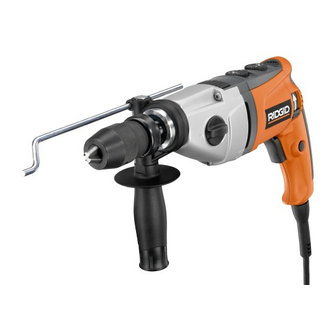
1/2 in. HAMMER/PULSE DRILL
DOUBLE INSULATED
R5010
Advertisement
Table of Contents

Related Manuals for RIDGID R5010


Summary of Contents for RIDGID R5010
- Page 1 When properly cared for, it will give you years of rugged, trouble-free performance. WARNING: To reduce the risk of injury, the user must read and understand the operator’s manual before using this product. Thank you for buying a RIDGID product. SAVE THIS MANUAL FOR FUTURE REFERENCE...
-
Page 2: Table Of Contents
TABLE OF CONTENTS n Introduction ..................................2 n General Safety Rules ..............................3-4 n Specific Safety Rules................................4 n Symbols..................................5-6 n Electrical ...................................7 n Features....................................8 n Unpacking ..................................9 n Assembly ..................................9-10 n Operation.................................. 11-13 n Adjustments ...................................14 n Maintenance ................................15-16 n Warranty ..................................17 n Customer Service Information............................18 INTRODUCTION... -
Page 3: General Safety Rules
GENERAL SAFETY RULES n Avoid accidental starting. Be sure switch is off before WARNING: plugging in. Carrying tools with your finger on the switch or plugging in tools that have the switch on invites acci- Read and understand all instructions. Failure to dents. -
Page 4: Specific Safety Rules
GENERAL SAFETY RULES SERVICE n When servicing a tool, use only identical replacement parts. Follow instructions in the Maintenance section n Tool service must be performed only by qualified re- of this manual. Use of unauthorized parts or failure to fol- pair personnel. -
Page 5: Symbols
SYMBOLS Some of the following symbols may be used on this tool. Please study them and learn their meaning. Proper interpreta- tion of these symbols will allow you to operate the tool better and safer. SYMBOL NAME DESIGNATION/EXPLANATION Volts Voltage Amperes Current Hertz... - Page 6 SYMBOLS The following signal words and meanings are intended to explain the levels of risk associated with this product. SYMBOL SIGNAL MEANING DANGER: Indicates an imminently hazardous situation, which, if not avoided, will result in death or serious injury. WARNING: Indicates a potentially hazardous situation, which, if not avoided, could result in Death or serious injury.
-
Page 7: Electrical
ELECTRICAL DOUBLE INSULATION When working outdoors with a tool, use an extension cord that is designed for outside use. This type of cord is desig- Double insulation is a concept in safety in electric power nated with “WA” on the cord’s jacket. tools, which eliminates the need for the usual three-wire Before using any extension cord, inspect it for loose or ex- grounded power cord. -
Page 8: Features
FEATURES SPECIFICATIONS Chuck Capacity............................... 1/2 in. (13 mm) Input ............................ 120 V, 60 Hz, AC only, 9.0 Amps Switch................................Variable Speed Hammer Speed ..............................0-57,000 BPM No Load Speed ......................Low (0-1,000/min) & High (0-3,000/min) AUXILIARY HANDLE ASSEMBLY Before using this tool, familiarize yourself with all operat- ing features and safety requirements. -
Page 9: Unpacking
UNPACKING INSTRUCTIONS PACKING LIST The drill has been shipped completely assembled. Hammer Drill with Auxiliary Handle Assembly n Carefully remove the tool from the box. Depth Gauge Rod n Make sure that all items listed in the packing list are Carrying Case included. - Page 10 ASSEMBLY TO INSTALL BITS RELEASE See Figures 4 and 5. (UNLOCK) n Unplug the drill. n Open or close the chuck jaws to a point where the open- ing is slightly larger than the drill bit you intend to use. CHUCK Also, raise the front of the drill slightly to keep the drill bit JAWS...
-
Page 11: Operation
OPERATION WARNING: Exercise caution when using this tool. Careless ac- tions, for even a fraction of a second, can result in serious personal injury. WARNING: Always wear safety goggles or safety glasses with side shields when operating this tool. Failure to do so could result in dust, shavings, or loose particles being thrown into your eyes, resulting in possible serious injury. -
Page 12: Variable Speed
OPERATION REVERSIBLE FORWARD FORWARD-REVERSE See Figure 7. CENTER LOCK OFF The drill has the feature of being reversible. The direction LEVER of chuck rotation is controlled by a switch located on either side of the drill housing. The design of the switch will not permit changing the direc- tion of rotation while the drill is running. - Page 13 OPERATION DRILLING See Figure 10. n Attach auxiliary handle. WARNING: Do not force the tool. Forcing the tool can result in jamming and loss of balance or footing, which could result in personal injury. n Depress and release switch trigger to be sure the drill is in OFF position before connecting it to power supply.
-
Page 14: Adjustments
ADJUSTMENTS ADJUSTING THE AUXILIARY HANDLE ASSEMBLY TIGHTEN See Figure 11. Follow these steps to adjust the auxiliary handle assembly. n Loosen the auxiliary handle assembly by turning the knob counterclockwise. n Rotate the auxiliary handle assembly to the desired location. n Tighten the auxiliary handle assembly securely by turning the knob clockwise. -
Page 15: Maintenance
MAINTENANCE WARNING: The tool should never be connected to a power supply when you are assembling parts, making adjustments, cleaning, performing maintenance, or when the tool is not in use. Disconnecting the LOOSEN tool will prevent accidental starting that could cause serious injury. - Page 16 When servicing use only identical RIDGID® replace- and grindings are highly abrasive to bearings, brushes, com- ment parts. Use of any other parts may create a mutators, etc.
-
Page 17: Warranty
This warranty covers all defects in workmanship or materials ability or fitness for a particular purpose, that cannot be in this RIDGID tool for the three year period from the date of disclaimed under state law are limited to three years from purchase. -
Page 18: Customer Service Information
R5010 Customer Service Information For parts or service, contact your nearest Ridgid authorized service center. Be sure to provide all relevant information when you call or visit. For the location of the au- thorized service center nearest you, please call 1-866-539-1710 or visit us online at www.ridgid.com.