GE NX-320E Installation Manual
Networx series remote power supply
Hide thumbs
Also See for NX-320E:
- Installation manual (24 pages) ,
- Installation and startup manual (20 pages)

Related Manuals for GE NX-320E


Summary of Contents for GE NX-320E
- Page 1 Security NetworX Series NX-320E Remote Power Supply Installation manual imagination at work...
- Page 2 NX-320E Installation manual Page 2 19/09/05...
-
Page 3: Table Of Contents
ONTENTS CONTENTS ....................................3 GENERAL INFORMATION................................4 ORDERING INFORMATION ................................. 4 INSTALLING THE NX-320E................................5 ENROLLING THE NX-320E REMOTE POWER SUPPLY ......................5 UNDERSTANDING THE LED’S..............................5 PROGRAMMING THE NX-320E POWER SUPPLY........................6 NX-320E ..............................6 ROGRAMMING THE VIA THE KEYPAD ENTERING THE PROGRAM MODE..................................6... -
Page 4: General Information
The NX-320E has three (3) programmable outputs and one (1) dedicated bell output. A maximum of four (4) NX-320E power supply modules can be added to the NetworX control panel NX-8 and a maximum of eight (8) power supply modules can be added to the NetworX control panel NX-8E. -
Page 5: Installing The Nx-320E
The first thing that must be decided is the address of this particular power supply. This is the address that will be selected when programming the NX-320E. To set the addresses use the table below. DIP switch 4 is used to disable the tamper feature of the NX-320E (“On” = enabled / “Off” = disabled). Location... -
Page 6: Programming The Nx-320E Power Supply
Since all modules connected to the NetworX are programmed through the keypad, the module you are programming should be the first entry. To program the NX-320E module, enter the address of the NX-320E, followed by [#]. See DIP switch chart on page 4. PROGRAMMING A LOCATION Once the number of the module to be programmed has been entered, the “Armed”... -
Page 7: Exiting The Program Mode
Note: the timeout for the program mode is 15 minutes. Programming the NX-320E via the LCD keypad All steps required for programming are the same as the aforementioned LED keypad. The LCD keypad display will prompt you for the data required. -
Page 8: Programming Data
[*] to enter the data, you will exit that location. This will now turn the “Ready” LED off and the “Armed” LED on. As before, you are now ready to enter another programming location. NX-320E Installation manual Page 8 19/09/05... -
Page 9: Programming The Locations
Entry or exit 31 u Panic keypad function expander) Siren tamper (control or Armed 32 u Code entry (set codes in expander) loc.8-17) u If set to follow condition, these events will be one second. NX-320E Installation manual Page 9 19/09/05... - Page 10 Segment 2 - time Is used to select the amount of time an output will remain activated when an output triggers. If this location is programmed as a zero, the output will follow the particular event. NX-320E Installation manual Page 10 19/09/05...
- Page 11 Segment 2 - time Is used to select the amount of time an output will remain activated when an output triggers. If this location is programmed as a zero, the output will follow the particular event. NX-320E Installation manual Page 11 19/09/05...
- Page 12 Code will activate Output A Code will NOT activate output A Code will activate Output B Code will NOT activate output B Code will activate Output C Code will NOT activate output C Reserved NX-320E Installation manual Page 12 19/09/05...
- Page 13 Location 13 contains 10 segments. Segment 1 corresponds to user 51, segment 10 corresponds to user 60. The LED’s correspond to outputs A - C. Refer to location 8 chart. NX-320E Installation manual Page 13 19/09/05...
- Page 14 (“0” minutes). If you desire the A/C delay to be 8 minutes and the dynamic battery test to be 3 minutes, you would program 8-3. NX-320E Installation manual Page 14 19/09/05...
- Page 15 LOCATION 19 - DEVICE OPTIONS (8 segments, feature selection data) Location 19 is used to enable various system features of the NX-320E power supply. Option Function AC report always If enabled, an AC Fail report will be sent if power is lost sent for the time programmed in location 18.
-
Page 16: Nx-320E Programming Worksheets
ON: for inverted output ON: disables output during listen-in Reserved Reserved Reserved Segment 2 (Circle Numbers To Program) Partition 1 Partition 2 Partition 3 Partition 4 Partition 5 Partition 6 Partition 7 Partition 8 NX-320E Installation manual Page 16 19/09/05... - Page 17 ON: for inverted output ON: disables output during listen-in Reserved Reserved Reserved Segment 2 (Circle Numbers To Program) Partition 1 Partition 2 Partition 3 Partition 4 Partition 5 Partition 6 Partition 7 Partition 8 Reserved NX-320E Installation manual Page 17 19/09/05...
- Page 18 Output C Codes 81-90 Output enable (circle the numbers to program) User Output A Output B Output C Codes 91-99 Output enable (circle the numbers to program) User Output A Output B Output C NX-320E Installation manual Page 18 19/09/05...
- Page 19 Device options (circle the numbers to program) On for AC report always sent; Off follows control On enables periodic battery test On enables low battery reporting On enables siren tamper/trouble reporting Reserved Reserved Reserved Reserved NX-320E Installation manual Page 19 19/09/05...
-
Page 20: Terminal And Led Descriptions
NX-320E board. DATA This terminal is the outgoing data-signalling terminal for buss extension. The maximum total wire run from the NX-320E to all outgoing devices is 800 m. Common terminal for any device powered from the NX-320E. OUT A Programmable output current limited to 1.5 Amps. -
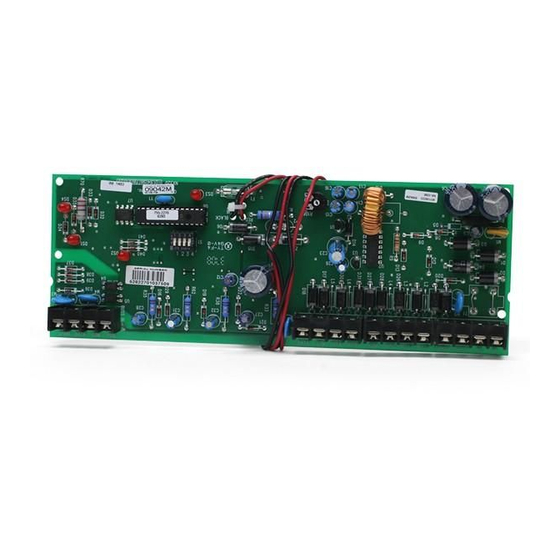
Page 21: Nx-320E Print Layout
NX-320E PRINT LAYOUT NX-320E Installation manual Page 21 19/09/05... -
Page 22: Enclosure Diagram
The second PCB guide should be positioned opposite of the first (grooved edge up) and placed in the lower insertion point, using the same procedures described above. Once mounted, screw it in securely. Diagram 3: The PC board should slide freely in the grooves of both guides. NX-320E Installation manual Page 22 19/09/05... -
Page 23: Technical Specifications
• 10 mA nominal: Output: • 13.85 Vdc/2A nominal: • 13.85 Vdc/2.5A maximum: Battery: max. 12 Vdc/18 Ah Operating temperature: 0 - 50° C Dimensions (PCB): 236 x 81 mm Weight (PCB): 185 g NX-320E Installation manual Page 23 19/09/05... -
Page 24: Ce Declaration
CE D ECLARATION NX-320E Installation manual Page 24 19/09/05... - Page 25 NX-320E Installation manual Page 25 19/09/05...
- Page 26 NX-320E Installation manual Page 26 19/09/05...
- Page 27 EMEA Distribution is a division of GE Security EMEA bvba COPYRIGHT ©2005 © GE Security EMEA bvba. All rights reserved. GE Security EMEA bvba grants the right to reprint this manual for internal use only. GE Security EMEA bvba reserves the right to change information without notice.