Table of Contents
Advertisement
Quick Links
Advertisement
Table of Contents

Related Manuals for XtendLan DVR-1670C


Summary of Contents for XtendLan DVR-1670C
- Page 1 DVR-1670C Digital video net recorder User’s Manual ...
-
Page 2: Table Of Contents
Table of contents FEATURES AND SPECIFICATIONS ..............9 Features ..............................9 Specifications............................9 INSTALLATION AND OPERATIONS .............. 12 Check Unpacked DVR ........................12 2.1.1 Open the box ........................... 12 About the front panel and the rear panel..................12 2.1.2 2.1.3 Check after opening the front cover .................... - Page 3 Mouse operation ..........................24 Input Methods............................. 24 3.6.1 Keyboard ............................24 3.6.2 Front Panel ............................25 DVR BASIC OPERATION ................26 Login/Logout/Main Menu......................... 26 4.1.1 Login ..............................26 4.1.2 Main menu............................26 4.1.3 Log out .............................. 27 4.1.4 Resume after Power Failure ......................27 4.1.5 Replace button battery ........................
- Page 4 4.10 Preset/ Patrol/Pattern/Scan Function ................... 43 4.10.1 Preset Setup ..........................44 4.10.2 Activate Preset ........................... 44 4.10.3 Patrol Setup (Tour setup)......................44 4.10.4 Activate Patrol (tour) ........................45 4.10.5 Pattern Setup ..........................45 4.10.6 Activate Pattern Function ......................45 4.10.7 Auto Scan Setup ........................
- Page 5 Exit ................................ 64 ABOUT AUXILIARY MENU ................65 6.1.1 Fast location key ..........................65 Preset /patrol / pattern border function ..................66 6.2.1 Preset setup............................. 67 6.2.2 Activate preset..........................67 6.2.3 Patrol setup............................67 6.2.4 Activate patrol..........................67 6.2.5 Pattern setup ........................... 67 6.2.6 Activate pattern function ........................
- Page 6 7.6.6 Motion Detection ..........................81 7.6.7 Network ............................. 81 7.6.8 Video Parameter ..........................82 Assistant.............................. 83 7.7.1 User Manage ........................... 83 7.7.2 Record control ..........................86 7.7.3 Log information..........................86 7.7.4 Date and time ..........................87 7.7.5 System information ......................... 87 7.7.6 Alarm Prompt...........................
-
Page 7: Important Safeguards And Warnings
Important Safeguards and Warnings 1Electrical safety All installation and operation here should conform to local electrical safety codes. We assume no liability or responsibility for all the fires or electrical shock caused by improper handling or installation. 2Transportation security Heavy stress, violent vibration or water splash are not allowed during transportation, storage and installation. - Page 8 Do not apply power to the DVR before completing installation. Do not place objects on the DVR 4Qualified engineers needed All the examination and repair work should be done by the qualified service engineers. We are nor liable for any problems caused by unauthorized modifications or attempted repair.
-
Page 9: Features And Specifications
● Powerful network software: built-in web server, multi-DVR client & CMS. Networking access for remote live viewing, recording, playback, setting, system status, event log, e-mail & ftp function. 1.2 Specifications Model DVR-1670C 16 channel audio/video basic model System Main Processor High performance embedded microprocessor... - Page 10 Video Compression H.264 Video Resolution Format NTSC D1 (4CIF) 704*480 704 * 576 352 *240 352 *288 Video Recording CIF: PAL 1f/s~25f/s NTSC 1f/s~30f/s D1: PAL 1f/s~6f/s NTSC 1f/s~7f/s Video Display Split Full and multiple screen display, 1 / 4 / 8 / 9 / 16 Tour Display Support Image Quality...
- Page 11 Overwrite Mode Support Raid Function Support Search Mode Time/Date, Alarm, Motion Detection & exact search (accurate to second) Playback 2 channel playback simultaneously, Play, pause, stop, rewind, fast play, slow play, next file, previous file, next camera, previous camera, full screen, repeat, shuffle, backup selection.
-
Page 12: Installation And Operations
2 Installation and Operations Note: All the installations and operations here should conform to your local electric safety code. 2.1 Check Unpacked DVR 2.1.1 Open the box When you receive the DVR from the shipping agency, please check whether there is any visible damage to the DVR appearance. -
Page 13: About Cd Burner
For a 4-ch DVR, the average capacity of HDD usage per hour per channel is 200M/h. Now if you hope the DVR can record the video 12 hours each day for 30 days, the total capacity of HDDs needed is: 4 channels * 30 days * 12 hours * 200 M/h = 288G. So you need to install one 300G HDD or 2 160G HDDs. -
Page 14: Audio Input
● Keep connection lugs in well condition The signal line and shielded wire should be firm and in well connection. Avoid dry joint, lap welding and oxidation. 2.3.2 Audio Input These series DVR uses BNC port. Due to high impedance of audio input, you need to use active acoustic pickup. Audio transmission is similar to video transmission. -
Page 15: Alarm Output
Alarm input: for D1/HD1series, 5~15v is needed for voltage alarm input. For CIF series, grounding signal is needed for alarm input. If you need to connect two DVRs or one DVR and other device, please use relay to separate them. 2.4.2 Alarm Output Do not connect alarm output port directly with high power load (no more than 1 A) in case of heavy current which will destroy the relay. -
Page 16: About Alarm Output End
These series DVRs use grounding alarm input (DVR activate an alarm when alarm input is connected to ground.} Please refer to Figure 2-2 for alarm input and output description. a) In “in” low, from left to right ALARM (1…16) are 16-channel grounding alarm input. -
Page 17: Record Modes Selection And Configuration
2 ways relay alarm output (normal open contacts). Provide power to external alarm device. To avoid over loading, please read the following relay parameters sheet carefully. (See below table) The controllable +12v can provide the power to restorable smoke detector. Relay specification Sliver Material of the touch... - Page 18 Please choose suitable bandwidth access mode when you connect in WAN. Ethernet cable should be made according to your local standard. Note: Please apply this manual to the right models. Do not use this manual to install or operate other series DVR.
-
Page 19: Installation And Operation
3 Installation and Operation 3.1 Hard Disk Installation Please follow the instructions below to install hard disk first. Dkfjdkfj 1. Remove the upper cover of the DVR 2. Remove the HDD bracket from internal unit 3. Dismantle the upper HDD bracket 4. -
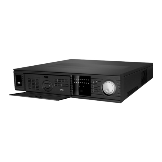
Page 20: Front Panel
9. Connect the HDD with IDE port through data communication cable 10. Connect power cord to the Dkfjdkfj 11. Place the upper cover back and screw firmly 12. Connect USB devices (USB mouse, USB removable HDD, USB CD-RW) to the USB port directly 3.2 Front Panel The front panel is shown as in Figure 3-1. - Page 21 When you need to input numeral more than 9. You can follow the Input numeral more steps below, click the first key number and then the next. than10 For example, input 123, click numeral 1 and then 2 and click 3(continuously).
-
Page 22: Rear Panel
In playback mode, playback the next video Play Next In menu setup, go to down ward of the dropdown list. Reverse playback or paused mode, click this button to realize normal playback In normal playback click this button to pause playback In pause mode, click this button to resume playback Play/Pause In real-time monitor mode, click this button to enter video search menu... -
Page 23: Remote Control
Figure 3-2 Serial number Power button Power outlet RS485 port RS232 port VGA port , USB, Network port(RS45) Audio 25-pin connection port Video input and output port(1/2 main/assistant) Note: When you use Ethernet connection, use crossover cable to connect with network card, use straight-through cable to connect PC via switch or hub. -
Page 24: Mouse Operation
forward Previous Back Stop Next Slow play Play/Pause Fast play 3.5 Mouse operation Left click mouse Have not login Pop up password input screen Real-time surveillance mode Enter the main menu In menu selection mode Enter the select item In combo box Pop up pull down list Click number box or pass word Select number keyboard or... -
Page 25: Front Panel
The system supports two input methods: numeral input and English character (small and capitalized) input. Move the cursor to the text column, the text shows as blue, input button pops up on the right. Click that button to switch between numeral input and English input (capitalized and small) Use >... -
Page 26: Dvr Basic Operation
4 DVR Basic Operation Before operation, please make sure you have properly installed HDD and all the cable connections are right. 4.1 Login/Logout/Main Menu 4.1.1 Login When system boots up, default video output is in multiple-window mode. Click Enter or left click mouse, you can see the login interface. See Figure 4-1. System consists of four accounts: ●... -
Page 27: Log Out
4.1.3 Log out In the main window, click shutdown button, you can see an image is shown as below. See Figure 4-3. Figure 4-3 There are several options for you. See Figure 4-4. Figure 4-4 Or you can click power button in the front panel for at least three seconds, system will stop all operations. - Page 28 There are two ways for you to go to manual record interface. ● In the main menu, Advanced->Manual Record. ● In preview mode, click record button in the front panel or record button in the remote control. Manual record interface is shown as in Figure 4-5. 4.2.2.2 Basic operation Here is for you to set manual record setup.
-
Page 29: Search
Please highlight “ALL” after “Schedule”. When system is in schedule recording, all channels will records as you have previously set (Main menu->Setting- >Schedule). The corresponding indication light in front panel will turn on. See Figure 4-7. Figure 4-7 ● All channel manual record Please highlight “ALL”... -
Page 30: Basic Operation
● Click Pause/Play button in the remote control. ● Click search icon in the main menu. Search interface is shown as below. See Figure 4-10. There are three file types: • R: regular recording file. • A: external alarm recording file. •... -
Page 31: File Backup During Search Operation
There are various search engines: video type, channel number or time. System can max display 32 files in one screen. You can use up/down button to turn page. Select the file name and double click mouse (or click enter button), you can view file content. -
Page 32: Backup In Search Interface
Fast forward(outer When playback, turn the shuttle ring clockwise) (outer ring) clockwise one round: you In forward or can view in fast speed 1 backward mode, Turn it two rounds you get fast double click speed 2. Pause/Play button You can continue turning to get to get normal different speed. -
Page 33: Record Setup (Schedule)
file list. In Figure 4-11, there are video files in March 13th and 14th. Double click date to view file list. Figure 4-11 4.4 Record Setup (Schedule) When system boots up, it is in default 24-hour record mode. You can set record type and time in schedule interface. - Page 34 • Record types: There are three types: regular, motion detection (MD) and Alarm. Please highlight icon to select the corresponding function. After all the setups please click save button, system goes back to the previous menu. At the bottom of the interface, there is a color bar for your reference. Green stands for schedule recording, yellow stands for motion detection and red stands for alarm recording.
-
Page 35: Detect
Figure 4-13 4.4.2.2.2 Playback or search file in the redundant disk There are two ways for you to playback or search in the redundant disk. ● Set redundant disk(s) as read-only disk or read-write disk (Main menu- >Advanced->HDD management). See Figure 4-13.System needs to reboot to get setup activated. -
Page 36: Video Loss
After all the setups please click save button, system goes back to the previous menu. In motion detection mode, you can not use copy/paste to set channel setup since the video in each channel may not be the same. In Figure 4-15, you can left click mouse and then drag to set a region for motion detection. - Page 37 • Record channel: select the channel to record when video loss occurred. • Alarm output: activate peripheral alarm device when video loss occurred. • Enable tour: Here is for you to activate tour. • Latch: when motion detection completes, system auto delays detecting for a specified time.
-
Page 38: Alarm Setup And Alarm Activation
In this interface, copy/paste function is only valid for the same type, which means you can not copy a channel setup in video loss mode to camera mask detect mode. Figure 4-18 4.6 Alarm Setup and Alarm Activation Before operation, please make sure you have properly connected alarm devices such as light or buzzer. -
Page 39: Backup
Figure 4-19 4.7 Backup Click backup icon in the main menu, there are two function items: detect device and backup files. 4.7.1 Detect Device Here is for you to view devices information. See Figure 4-20. Figure 4-20 Detect device 4.7.2 Backup Select backup device and then channel, file start time and end time. - Page 40 Figure 4-21 Click backup button, system begins burning. At the same time, the backup button becomes stop button. You can view the remaining time and process bar at the left bottom. See Figure 4-22. Figure 4-22 Tips: During backup process, you can click ESC to exit current interface; but system will not terminate backup process.
-
Page 41: Ptz Control And Color Setup
The file name format usually is: SN_CH+channel number+time Y+M+D+M+S, In the file name, the YDM format is the same as you set in general interface. (Main Menu - >Setting ->General). You can visit our website to view listed CD-ROM type. 4.8 PTZ Control and Color Setup Note: All the operation here is based on DH-SD protocol. - Page 42 Figure 4-24 After all the setting please click save button. In one window display mode, right click mouse (click “Fn” Button in the front panel or click “Fn” key in the remote control). The image is shown as in Figure 4-25: Figure 4-25 Click Pan/Tilt/Zoom, the image is shown as below.
-
Page 43: Intelligent Positioning Key
In Figure 4-26, please click direction arrows (See Figure 4-27) to adjust PTZ position. There are totally 8 direction arrows. Figure 4-27 4.9.1 3D intelligent positioning Key In the middle of the eight direction arrows, there is a 3D intelligent positioning key. See Figure 4-28 . -
Page 44: Preset Setup
● Patrol(Tour) ● Pattern ● Aux on ● Aux off ● Auto scan ● Auto pan ● Light on Figure 4-30 Note: The following setups are usually operated in the Figure 4-26, Figure 4-29 and Figure 4-30. 4.10.1 Preset Setup In Figure 4-26, use eight direction arrows to adjust camera to the proper position. -
Page 45: Activate Patrol (Tour)
Figure 4-32 4.10.4 Activate Patrol (tour) In Figure 4-29, input patrol (tour) number in the No. blank and click patrol button 4.10.5 Pattern Setup In Figure 4-29, click pattern button and then click “begin” button. The image is shown as in Figure 4-33. Then you can go to Figure 4-26 to modify zoom, focus, and iris. Go back to Figure 4-33 and click “end”... -
Page 46: Activate Auto Scan
Figure 4-34 4.10.8 Activate Auto Scan In Figure 4-30, click “Auto Scan” button, the system begins auto scan. Correspondingly, the auto scan button changes to stop button. Click stop button to terminate scan operation. 4.11 Dome Menu Control In Figure 4-30, click page switch button, the image is shown as below. See Figure 4-35. Click menu to enter dome menu. -
Page 47: Menu Operation
5 Menu operation 5.1 Menu tree These series DVR menu tree is shown as below. 5.2 Main menu When you login, the system main menu shows as below. See Figure 5-1 . There are totally six icons: search, Information, setting, backup, advanced and shutdown. Move the cursor to highlight the icon, then double click mouse to enter the next menu. -
Page 48: System Setting
Figure 5-1 main menu 5.3 System setting In main menu, highlight setting icon and double click mouse. System setting window is shown as below. See Figure 5-2. Figure 5-2 system setting 5.3.1 General General setting includes the following items. See Figure 5-3. ●... -
Page 49: Encode
Figure 5-3 General 5.3.2 Encode Encode setting includes the following items. See Figure 5-4. • Channel: Select the channel you want. • Compression: system supports two formats: MPEG4/H.264 • Resolution: System supports various resolutions, you can select from the dropdown list. •... -
Page 50: Schedule
Figure 5-4 5.3.3 Schedule Please refer to chapter 4.4 schedule. 5.3.4 RS232 RS232 window is shown as below. Here are five items. See Figure 5-5. • Function: There are various devices for you to select. • Baud rate: You can select proper baud rate. •... - Page 51 • Max connection: support maximal 10 users. • Authorization: Click authorization button please highlight icon to enable IP authentication function. When you enable this function, only IP in the list can login this DVR. See Figure 5-7. After all the setups please click save button, system goes back to the previous menu. Figure 5-6 Network Figure 5-7 5.3.5.1 PPPoE Connection...
-
Page 52: Alarm
b. Visit via DNS You need a PC of fixed IP in the internet and there is the DDNS software running in this PC. In other words, this PC is a DNS (domain name server). In network DDNS, input your PPPoE name you get from you IPS and server IP (PC with DDNS ) . -
Page 53: Default
• Channel display: You can select channel name or not. • Overlay information: System displays some information in the screen for your reference. • Enable tour: activate tour function. • Interval: Input proper interval value here. The value ranges from 5-200 seconds. -
Page 54: Search
System menu color, language, time display mode, video format, IP address, user account will not recover after default operation! Figure 5-10 Default 5.4 Search Please refer to chapter 4.3 Search. 5.5 Advanced Double click advanced icon in the main window, the image is shown as below. See Figure 5-11. -
Page 55: Alarm Output
Figure 5-12 HDD management Click alarm set button, the image is shown as below. See Figure 5-13. Please highlight icon to select the corresponding function. You can set one or more alarm setups. The lower limit ranges from 1% to 99%. Alarm channel number ranges from 1 to 6. -
Page 56: Alarm Input
5.5.3 Alarm input Here is for you to set alarm input. Please highlight icon to select the corresponding input channel. After all the setups please click save button, system goes back to the previous menu. See Figure 5-15. Figure 5-15 Alarm input 5.5.4 Manual record Please refer to chapter 4.2.2 manual record. -
Page 57: Auto Maintain
Figure 5-16 account 5.5.6 Auto maintain Here you can set auto-reboot time and auto-delete old files setup. See Figure 5-17. You can select proper setup from dropdown list. After all the setups please click save button, system goes back to the previous menu. Figure 5-17 Auto maintain 5.5.7 TV adjust Here is for you to adjust TV output setup. - Page 58 They are just the same with video distributors. There are 16-ch video loop outputs from our DVR. The DVR video output can connect with other devices such as TV walls, analog matrix and so on. 5.5.8.2 Matrix outputs They are like the small-scale matrix. You can select any camera from our DVR to switch.
- Page 59 Figure 5-21 Menu Right mouse menu 5.5.8.5.2 3.2. Right click the mouse to select “Video Matrix”. See Figure 5-22. Figure 5-22 Right mouse menu 5.5.8.6 Video Matrix Interface and Application The video matrix window is shown as in Figure 5-23.Now it support 4-channel matrix outputs.
- Page 60 First, highlight enable tour. Then set interval time and select corresponding cameras. You can select “ALL” to tour between all channels. Only Group 1 supports “ ALL “function. Note: • ”- -“means that there is no alarm activation tour. • If you have selected the “ALL” for the matrix output in Group 1, the matrix output will tour between all cameras and the other groups setting will be null.
-
Page 61: Information
Figure 5-25 Example one 5.5.8.7.2 Example two In Figure 5-26, when alarm occurs in channel one, the activated matrix output one begins touring between CAM1, CAM3 and CAM4 of the DVR until alarm activation tour stops. Figure 5-26 Example two 5.6 Information Here is for you to view system information. -
Page 62: Hard Disk Information
Figure 5-27 5.6.1 Hard disk information Here is to list hard disk type, total space, free space, video start time and status. See Figure 5-28. Note: Please remove the broken hard disk before you add a new one. Once there is a hard disk confliction, please check hard disk time and system time is the same or not. -
Page 63: Log
Figure 5-29 BPS 5.6.3 Log Here is for you to view system log file. System lists the following information. See Figure 5-30. Figure 5-30 Log 5.6.4 Version Here is for you to view some version information. See Figure 5-31. ● Channel ●... -
Page 64: Exit
You can disconnect one user or block one user. (You need to have proper right) Figure 5-32 Online users 5.7 Exit Double click exit button, system pop up a dialogue box for you to select. See Figure 5-33. ● Logout menu user: log out menu. You need to input password when you login the next time. -
Page 65: About Auxiliary Menu
6 About Auxiliary Menu In the single window surveillance screen, right click mouse (click “fn” Button in the front panel or click AUX key in the remote controller). The image shows as below: see Figure 6-1. Figure 6-1 Shortcut menu Click Pan/Tilt/Zoom, the image shows as below. -
Page 66: Preset /Patrol / Pattern Border Function
Figure 6-4 Fast location key Here is a sheet for you reference. Name Function function Shortcut Function function Shortcut Near Zoom ► Focus Near ► Iris close Open 6.2 Preset /patrol / pattern border function In Figure 6-2 click the set button. The image shows as below: Here you can set the following items: ●... -
Page 67: Preset Setup
Figure 6-6 activate function 6.2.1 Preset setup Note: The following setups are usually operated in the Figure 6-2, Figure 6-5 and Figure 6-6. In Figure 6-2, use eight direction arrows to adjust camera to the proper position. In Figure 6-5, click preset button and input preset number. The image is shown as in Figure 6-7 Add this preset to one patrol number Figure 6-7 Preset setup... -
Page 68: Activate Pattern Function
Figure 6-9 Pattern setup 6.2.6 Activate pattern function In Figure 6-6 input mode value in the No. blank, and click pattern button. 6.2.7 Border setup In Figure 6-5, click border button. The image shows like Figure 6-10. Please go to Figure 6-2, use direction arrows to select camera left limit, and then please go to Figure 6-10 and click left limit button Repeat the above procedures to set right limit. -
Page 69: Web Client Operation
7 Web client operation Please note, all the operation here in chapter seven is using 16-ch as an example. There might be slightly difference in the interface due to different series. 7.1 Network connection Before web client operation, please check the following items: ●... -
Page 70: Go To Real-Time Monitor Mode
Figure 7-3 7.3 Go to real-time monitor mode There are three ways for you to go to real-time monitor mode. ● Select the channel number besides function key. See Figure 7-4. Figure 7-4 ● Click video then select real-time monitor, click the channel number you wan to view. -
Page 71: Real Time Monitor
Figure 7-5 7.4.1 Real time Monitor Here is for you to select the channel you wan to implement real-time monitor. 7.4.2 Multi-camera Preview Here is for you to select view modes: 1/2/3/4/9/16. 7.4.3 Start Dialog Click this button to enable audio talk function. 7.4.4 Decode quality Here is for you to select decode quality. -
Page 72: Volume Adjustment
Figure 7-8 Here is for you to control direction operation. There are eight levels ranging from 1 to 8. Level 8 is the fastest speed. In Figure 7-8, click PTZ set button. You can see the following dialogue box. See Figure 7-9. -
Page 73: Network Data Flux
Figure 7-11 7.4.9 Network data flux Here is to display the statistics of the network transmission data flux. See Figure 7-12. Figure 7-12 7.4.10 Full screen There are two ways to view full screen monitor: One is to double click on the current monitor window directly;... -
Page 74: Search
Figure 7-14 7.5 Search Here you can select video type, channel number and time to search the file you want. Click search button, the image is shown as below. See Figure 7-15 Please use page up/down key to view the search results. Double click file name, you can view the file and system will automatically backup the image in you installation directory. -
Page 75: Download
Figure 7-16 7.5.1 Download You can select one or more files you want to download and then click down load button. System pops up a dialogue box asking you specify directory. See Figure 7-17. Figure 7-17 Then you can input file name and click save to backup file in your local pc. During the download process, there is a process bar for you reference. -
Page 76: System Settings
Figure 7-18 Download file name is usually made up of: file name +Channel N +date +time. File extension name is .dav. For example: file name a-0120021205071028.mp4 means: ● 01: channel 1 ● 20021205: 5 December,2002 ● 071028:7 o’clock 10 minutes 28 seconds. 7.6 System settings Click configure button, there are totally seven function keys. -
Page 77: Load And Save Configuration
Figure 7-19 7.6.1 Load and Save Configuration 7.6.1.1 Save configuration Click export configuration button in Figure 7-19.You can save current configuration to a directory. The file extension name is CFG. See Figure 7-20. Figure 7-20 7.6.1.2 Load configuration Click import configuration button in Figure 7-19.You can draw a √ before checkbox to load you previously backup file. -
Page 78: General
Figure 7-21 7.6.2 General Click general button, the image is shown as below. See Figure 7-22. Here you can select file length, and choose overwrite the previous file or stop recording when disk is full. You can select channel number, protocol, address and baud rate to control the lens or PTZ. -
Page 79: Image
Figure 7-23 7.6.4 Image Click image button, the system is shown as below. See Figure 7-24. Here you can select the image quality and protocols for each channel. Here you can set encode mode, quality and protocol for each channel. You can select from the dropdown list. -
Page 80: Alarm
Figure 7-24 7.6.5 Alarm Here is for you to choose record channel and output port. See Figure 7-25. There are two alarm types: normal open or normal close. Delay time ranges from 10 to 300 seconds. You can draw a √ before the check box to enable record camera and output port. Figure 7-25... -
Page 81: Motion Detection
In Figure 7-25 click alarm PTZ button, you can see the following interface. See Figure 7-26. There are three options: preset, auto scan and tour. Figure 7-26 7.6.6 Motion Detection Motion detection will take effect exclude the time you set to schedule recording. See Figure 7-27. -
Page 82: Video Parameter
Set PPPOE as on, and then please input “PPPoE name” and “PPPoE password” you get from your ISP (Internet service provider). After saving it, you need to restart to active your configuration. After rebooting, IP camera will connect to internet automatically. The IP in the PPPoE IP is the dynamic value. -
Page 83: Assistant
After having finished all channels setup, you can click <save> at the button to save all configurations. Figure 7-29 7.7 Assistant Click assistant setting, the image shows as below. See Figure 7-30. There are nine function keys. Please note Matrix control item only applies for some special series. Figure 7-30 7.7.1 User Manage Here is for you to manage users and user groups. - Page 84 Figure 7-31 7.7.1.1 Add Group Click <add group> to input group name. See Figure 7-32. Figure 7-32 Click <Power> to set group power. Click <Save> to save configuration 7.7.1.2 Delete Group Click <Delete Group> the image is shown as in Figure 7-33. Note: You can only delete empty group (E.g.: There is no user in current group).
- Page 85 7.7.1.4 Add User Figure 7-35 Click <Add User> the image is shown as in Figure 7-35 Input user name, password, group, you can click confirm password 7.7.1.5 Power When you add new user or new group (such as in Figure 7-32,Figure 7-35. ), click power button, the image is shown as in Figure 7-36.
-
Page 86: Record Control
Click delete user button, system pops up a dialogue box to ask your confirmation. See Figure 7-38. Figure 7-38 7.7.2 Record control Click record control button the image is shown as below. See Figure 7-39. You can select mode for each channel. Figure 7-39 7.7.3 Log information Systems automatically backup all operation in log information. -
Page 87: Date And Time
7.7.4 Date and time Here you can select system date and time. See Figure 7-41. Figure 7-41 7.7.5 System information System information allows you to view basic information of the system. See Figure 7-42. Here you can ● Turn on/off audio ●... -
Page 88: Channel Name
Figure 7-43 7.7.7 Channel Name Here is for you to modify channel name. The revised channel names will be displayed on the screen. The default setting of the channel name is Channel No.1 to Channel No.16. See Figure 7-44. Please note when you modify channel name in DVR end, this modification not applies to web end or standalone end,you need to use this interface to refresh. -
Page 89: Matrix (Only Applies For Some Series Dvr)
Click reboot button, system pops up a warning dialogue box to alert you. See Figure 7-46. Figure 7-46 7.7.10 Matrix (Only applies for some series DVR) Matrix control interface is shown as in Figure 7-47. Figure 7-47 7.7.11 About Here is for you to view basic system information. See Figure 7-48. Figure 7-48 7.8 Un-install web control There are three ways for you to un-install web control. -
Page 90: Serial Port Operation
8 Serial Port Operation 8.1 Network Connection Before serial port operation, please connect matrix with DVR through RS232. Then set DVR serial port protocol to the corresponding matrix protocol. Note: please contact you local retail to confirm the DVR supports matrix protocol or not. -
Page 91: Faq
9 FAQ 1. This system can run in windows 98 or not? Please install DIRECTX 7.0 or higher manually if you want to run this system in windows 98 environment. 2. System can not detect hard disk. First check whether the hard disk is broken. Then check jumper, IDE data cable and power cord. - Page 92 ● Invalid password or username Please check user name has been user or password is not right. 10. At the first beginning, the surveillance video is poor when I connected to server. If the image can return to normal in five seconds, this phenomena is normal 12.