Table of Contents
Advertisement
Quick Links
Advertisement
Table of Contents

Related Manuals for Panasonic WJ-ND300A/G


Summary of Contents for Panasonic WJ-ND300A/G
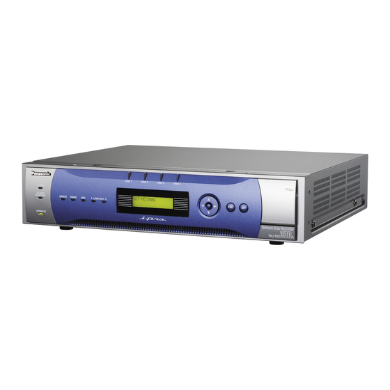
- Page 1 Network Disk Recorder Setup Instructions WJ-ND300A Model No. WJ-ND300A/G Before attempting to connect or operate this product, please read these instructions carefully and save this manual for future use. The model number is abbreviated in some descriptions in this manual.
-
Page 2: Table Of Contents
CONTENTS Preface ..........................3 Features ........................3 About these Operating Instructions ................4 System Requirements for a PC ................... 4 Trademarks and Registered Trademarks ..............4 Abbreviations ......................5 Terms Used in these Operating Instructions ............... 5 Operations Flow ......................7 Performing the Network Settings .................. -
Page 3: Preface
Preface Features The Network Disk Recorders WJ-ND300A series are designed for use within a surveillance system, and perform recordings and playbacks pictures from network cameras in the system. The network disk recorder is a recording device using a hard disk drive to record camera pictures instead of using video tapes so that pictures recorded by repeated overwriting will not experience deterioration of the recorded pic- ture quality. -
Page 4: About These Operating Instructions
These "Setup Instructions" contain descriptions of how to perform the required settings to operate this unit using a PC via a network and descriptions for installations such as how to connect the unit to other devices. The network settings of the unit will be different depending on the settings of the LAN or the Internet service provider to which the unit is to be connected. -
Page 5: Abbreviations
SD memory recording/SD memory data Function featured in some Panasonic’s cameras that saves images on the SD memory card on the camera when communication with the camera failed in the period set for the schedule recording of this unit. Images saved by the SD memory recording are described as "SD memory data"... - Page 6 External recording mode Function for changing the time schedule through an external switch connected to this unit. While the switch is turned on, recording is performed according to the time schedule specified for external recording. Event An event is a phenomenon which triggers a specific operation (event operation) in the unit. Events are divided into terminal alarm, command alarm, and site alarm.
-
Page 7: Operations Flow
Operations Flow The operation flow of this unit is as follows. Install the unit in the rack. Refer to the Installation Guide for further information Rack Mounting about rack mounting. Refer to the provided Installation Guide for further infor- mation about connections. Connections Turn on the power of the unit. -
Page 8: Performing The Network Settings
Performing the Network Settings With the following network environment, it is not necessary to perform the network settings. It is possible to perform the settings or operate this unit using a web browser after completing the connection. IP Address: 192.168.1.2 - 192.168.1.249, 192.168.1.251 - 192.168.1.254 Subnet mask: 255.255.255.0 Gateway Address: 192.168.1.1... - Page 9 Screenshot 2 The IP address setup display will be displayed. Step 2 Press the [SET] button. Screenshot 3 The DHCP Setup window will be displayed. Step 3 Select the desired network port by pressing the arrows button (A or B). PT#1: Camera port >...
-
Page 10: Performing The Network Settings Of A Pc
Performing the Network Settings of a PC Change the TCP/IP setting of the PC to conform to the settings of this unit. It is required to set the IP address of the PC to "192.168.1.XX (a number from 2 to 254 except 250)" to access this unit. - Page 11 Screenshot 3 The "Network and Internet Connections" window will be Step 3 displayed. Click "Network Connections". Screenshot 4 The "Network Connections" window will be displayed. Step 4 Double click "Local Area Connection". Screenshot 5 The "Local Area Connection Status" window will be dis- Step 5 played.
- Page 12 Screenshot 6 The "Local Area Connection Properties" window will be Step 6 displayed. Click "Internet Protocol (TCP/IP)", and then click "Properties". Screenshot 7 The "Properties" window of "Internet Protocol (TCP/IP)" Step 7 will be displayed. Click "Use the following IP address" and enter the IP address and the subnet mask as follows;...
-
Page 13: About The Network Security Of This Unit
About the Network Security of this Unit Equipped Security Functions q Access restrictions by the host authentication and the user authentication It is possible to restrict users from accessing this unit by setting the host authentication and/or the user authenti- cation to on. -
Page 14: Display The Operation Window
Display the Operation Window To display the operation window to operate the unit from the web browser installed on the PC, proceed as follows. Screenshot 1 Start just after the PC is started up. Step 1 After the browser starts, enter the IP address set to this unit in the address box, and press the enter key. - Page 15 Important: When the unit is being operated without changing the default administrator name and password, the pop-up window saying that it is recommended to change the password will be displayed. Screenshot 3 The top page will be displayed. Step 3 Click the buttons or the tabs for operations.
-
Page 16: About The Operation Window
About the Operation Window Top Page [Setup] tab Status display area Current time display area [Cam Select] tab Time and date of the [Control] tab selected camera Camera title Playback image display area Playback point operation area [CAM] tab [HDD] tab [Control] tab (page 17) Playback image display area This tab is for performing operations such as searching... -
Page 17: [Control] Tab
[Control] Tab The lamp on the button lights (green) during sequence operation. [EL-Zoom] box Camera images will be displayed in the proportion of the clicked zoom ratio button. [Search] box [Search] button: The recording event search will be displayed. Use this button to search the recorded images. -
Page 18: [Cam Select] Tab
[Cam Select] Tab [Multiscreen Select] box Multiscreen button: Up to 4 camera images can be displayed simultaneous- ly on a multi-screen. Each time the button is clicked, the camera picture is changed to quad display according to the settings made in [System] –... -
Page 19: [Setup] Tab (Quick)
[Setup] Tab (Quick) Display Setup This button is for performing basic settings such as date, time, and language display. Refer to page 28 for further information. Camera Setup This button is for performing camera network settings and group settings. Refer to page 30 for further informa- tion. -
Page 20: [Setup] Tab (Advanced)
[Setup] Tab (Advanced) Main menu [System] button The menu for the required system settings to activate this unit will be displayed. Refer to page 42 for further information. [Recording] button The menu for the recording settings will be displayed. Perform the basic settings for recording and the settings for emergency recording. -
Page 21: Status Display Area
Status Display Area q The status of live/playback image will be – [Step 1] – [Step 7]: displayed. Indicates the playback speed. (LIVE]: Step 1: Normal playback speed Indicates that a live image is being displayed. Step 2: Approx. 4x playback speed (Playback): Step 3: Approx. - Page 22 e Indicates the following statuses: [BUSY]: Indicates that the camera is not operable because a user with higher priority is currently operating that camera. [COPY]: Indicates that copying is being performed. [DELETE]: Indicates that deletion of a recorded image is being performed.
-
Page 23: Playback Point Operation Area
Playback Point Operation Area q Indicates the start time and the end time of a down- [GO TO DATE] button load or a A-B repeat. (Refer to the Operating Indicates the time and date of a marked point. Use Instructions (PDF).) this button to designate the desired time and date of [Start] button a recorded image to be played. - Page 24 [A-B Repeat] box The A-B repeat playback will be performed. Important: [START] button • To display the recording button and the recording Starts repeated playback of images between the A-B stop button, hold down the button until they are repeat start/end points. displayed.
-
Page 25: [Cam] Tab
[CAM] Tab Control pad/buttons [Zoom] box [Brightness] box Zooming can be adjusted by clicking the [Wide] The brightness can be adjusted by clicking the button or the [Tele] button. Click the [Close] button or the [Open] button. It is possible button to reset zoom. -
Page 26: Setup Menu (Quick)
Setup Menu (Quick) Performing each setting item on the setup menu should be completed in advance to operate this unit. The setup menu operations are performed from the [Setup] tab. Using the setup menu (Quick) and the setup menu (Advanced). First, check the settings items of the setup menu (Quick) and perform the settings. - Page 27 Screenshot 2 The setup menu (Quick) will be displayed. Step 2 Click an item on the setup menu (Quick). Note: When "ADVANCED" is selected for "REC Type" of "Rec & Event Setup" on the setup menu (Quick) (page 32) the setup menu (Advanced) will be dis- played when the [Setup] tab is clicked.
-
Page 28: Display/System Settings [Display Setup]
Display/System Settings [Display Setup] Perform the time and date, display settings such as the time and date display, the camera title display, the sequen- tial display and the language setting. Screenshot 1 Click "Display Setup" on the setup menu (Quick) to dis- Step 1 play the display settings window. - Page 29 Select "SPOT" or "4 Screens" as the sequence. [PRESET] Clicking the [SET] button for the selected sequence will Enter a camera preset position (blank, 1 to 256). When display the following window for setting the various no position is entered (blank), the camera does not items.
-
Page 30: Camera Network Settings And Group Settings [Camera Setup]
Camera Network Settings and Group Settings [Camera Setup] Performs network settings such as camera IP address and port number, and group settings. Screenshot 1 Click "Camera Setup" on the setup menu (Quick) to dis- Step 1 play the camera setting window. Click the [SETUP] button and perform the settings for each item. -
Page 31: [Rec & Event Setup]
[USER ID] Group Setup Set the user ID for accessing the cameras and logging Displays the group title of the camera. The following in. Enter up to 32 alphanumeric characters. window will be displayed when the [SETUP] button is clicked. [PASSWORD] Click the [SET] button after completing the settings, and Set the password for accessing the cameras and log-... - Page 32 Disabled "WARNING REPORT MAIL" Disabled "FTP ALARM SENDING" Disabled "ALARM MESSAGE" Functions normally (Fixed to "ON".) "Panasonic Alarm Protocol" Disabled "ALARM MAIL" Disabled Program Program 1 - 4 The settings performed on the setup menu (Advanced) will not be validated.
- Page 33 Important • When the result value is beyond the maximum network speed of the unit, the following may occur due to the heavy network traffic: • Some images to be recorded may not be done. • Some live images to be displayed may not be done. •...
- Page 34 I LIVE VIDEO I EVENT SETUP Set the transmission rate of live images from cameras. Perform the settings for the alarm output duration and The following are available for the transmission rate. the buzzer sound duration at an event (site alarm, termi- OFF/0.1 ips/0.2 ips/0.3 ips/0.5 ips/1 ips/2 ips/3 ips/ nal alarm or command alarm) occurrence.
-
Page 35: Perform The Settings For Network [Network Setup]
Perform the Settings for Network [Network Setup] Basic settings for a network connection can be performed with this menu. Screenshot 1 Click the "Network Setup" on the setup menu (Quick). Step 1 The "Network Setup" window will be displayed. Perform the settings for each item. Refer to the following for further information about the settings for each item. - Page 36 I Port Setup Perform the settings for the following items for each port. [DHCP] Select ON or OFF to determine whether or not to use the DHCP server. Select "ON" to obtain an IP address, a subnet mask and a gateway address from the DHCP server. Set to "OFF" when entering the addresses above manually.
-
Page 37: Setup Menu (Advanced) Chart
Setup Menu (Advanced) Chart Performing each setting item on the setup menu should be completed in advance to operate this unit. The setup menu is operable on this tab. Using the setup menu (Quick) and the setup menu (Advanced). First, check the settings items of the setup menu (Quick) and perform the settings. - Page 38 Panasonic Alarm protocol It is possible to send a message to addresses registered in advance using "Panasonic Alarm Protocol" when an event or a problem occurs. To receive messages using this function, the optional software is necessary.
- Page 39 Setup menu Description Page Maintenance Product Information Versions of the software, the hardware (this unit) , MAC address, temperature inside the unit and software version of the connect- ed extension unit will be displayed. Disk Information Hard disk information such as available capacity of the built-in hard disk or an extension unit will be displayed.
-
Page 40: Basic Operation With The Setup Menu (Advanced)
Basic Operation with the Setup Menu (Advanced) Screenshot 1 Start operation from the top page. Step 1 Click the [Setup] tab. Screenshot 2 The setup menu (Advanced) will be displayed. Step 2 Click the desired setup menu (Advanced). Note: When "QUICK" is selected for "REC Type" of "Rec & Event Setup"... - Page 41 Screenshot 3 The submenus respective to the clicked button on the Step 3 setup menu (Advanced) will be displayed. Click the desired submenu on the setup menu (Advanced). Submenu Screenshot 4 The settings page of the selected submenu will be dis- Step 4 played in the image display area.
-
Page 42: Perform The Settings For The System [System]
Perform the Settings for the System [System] Perform the settings for the system of this unit. Perform the basic settings for the system [Basic Setup] Perform the settings for the basic operations of this unit. Screenshot 1 Click the [System] button in the setup menu (Advanced) Step 1 and then click "Basic Setup". - Page 43 I Buzzer (Error) Perform the settings for sounding a buzzer at an error occurrence. OFF: A buzzer will not sound at an error occurrence. 1 s - 30 s (in 1 second intervals)/40 s/50 s/1 min/3 min/ 4 min/5 min (in 1 minute intervals): The buzzer that started sounding at an error occur- rence will sound for the selected period.
- Page 44 Setup items I Date Format Select a date format to be displayed from the following. Important: (Ex. April 1, 2007) • Recording will not be performed for around 4 sec- YY.MM.DD: 07.04.01 onds when changing the present time (accurate MMM.DD.YY: APR.01.07 within ±5 seconds) using the time adjustment input DD.MMM.YY: 01.APR.07 (pin no.20).
- Page 45 I Summer Time (Daylight Savings) Table Set the start (ON)/end (OFF) date and time for summer time. The following window will be displayed when the [SETUP] button is clicked. Click the [SET] button after completing the settings, and close the window by click- ing the [×] button at the top right of the window.
-
Page 46: Functions For Recording [Recording]
"ADVANCED". Submenu Setup items Status Time Table "FTP SEND BY PERIODIC TIMER" Disabled "WARNING REPORT MAIL" Disabled "FTP ALARM SENDING" Disabled "ALARM MESSAGE" Functions normally (Fixed to "ON".) "Panasonic Alarm Protocol" Disabled "ALARM MAIL" Disabled... - Page 47 Submenu Setup items Status Program Program 1 - 4 The settings performed on the setup menu (Advanced) will not be validated. The settings performed on the setup menu (Quick) will be validated. * Special Days Disabled * To perform the schedule recording, perform the settings for "Time Table" and "Program". •...
- Page 48 Settings for emergency recording [Emergency REC] Perform the settings for emergency recording such as the recording time or recording rate. Refer to the provided operating instructions for further information about emergency recording. camera channel such as the recording rate or image Screenshot 1 quality.
-
Page 49: Functions For Events [Event]
Functions for Events [Event] Perform the settings for event actions of each event type (site alarm, terminal alarm and command alarm). Refer to the provided operating instructions for further information about each event type. Basic settings for event actions [Basic Setup] Perform the settings relating to event actions such as the alarm output duration and the buzzer sound duration of each camera channel at an event occurrence (site alarm, terminal alarm, command alarm). - Page 50 Settings relating to the terminal alarm [Terminal Setup] Set event actions at a terminal alarm occurrence for each camera channel. Screenshot 1 Click the [Event] button in the setup menu (Advanced) Step 1 and then click "Terminal Setup" to display the "Terminal Perform the settings for the following items for each ter- Setup"...
- Page 51 Perform the settings for site alarm [Site Alarm Setup] Perform the settings relating to the site alarm such as the setting to validate or invalidate the original alarm from cameras, the port number used for receiving the original alarm, and the event actions for each camera channel at an original alarm occurrence.
- Page 52 Perform the settings for command alarm [Command Alarm] Set event actions at a command alarm occurrence for each camera channel. Screenshot 1 Click the [Event] button in the setup menu (Advanced) Step 1 and then click "Command Alarm" to display the Perform the settings for the following items for each "Command Alarm"...
-
Page 53: Settings For The Recording/Event Schedule [Schedule]
Settings for the Recording/Event Schedule [Schedule] Perform the settings for the recording schedules by designating a day of the week and time. It is possible to divide a day into 6 time zones and create a schedule by assigning programs to each time zone. Up to 4 programs can be created. - Page 54 Screenshot 2 The "Program Setup" window will be displayed. Step 2 Perform the settings for each item. Refer to the following for further information about the settings for each item. When the [camera 17-32] button is clicked, the setting window for camera 17-32 will be displayed. Step 3 Click the [SET] button after completing the settings, and close the window by clicking the [×] button at the top...
- Page 55 Images failed to obtain can be The SD memory recording is the function of some obtained automatically next time. Panasonic’s cameras that saves images on the SD memory card on the camera when communication with the camera failed in the period set for the schedule...
- Page 56 I [Measurement] button It is possible to check if the set recording rate and trans- Important mission rate are available for the network in use by • When the result value is beyond the maximum net- clicking this button. It will take around 90 seconds to work speed of the unit, the following may occur due check.
- Page 57 Set the time zone and assign programs [Time Table] Create recording timetables for each day of the week, and assign a recording program to each timetable. Up to 6 recording programs can be created for each day of the week. Screenshot 1 Click the [Schedule] button in the setup menu Step 1...
- Page 58 (or error information) to a click the [Copy] button. PC according to the "Panasonic Alarm protocol" of the setup menu ("Comm" – "Panasonic Alarm protocol") I New Time Table Setup (page 74).
- Page 59 Perform the settings of recording programs for special days [Special Days] Assign timetables to special days aside from other days of the week. Timetables for special days can be set for up to 30 days. Perform the settings to specify dates as special days and apply a recording schedule to the specified special days. Screenshot 1 Click the [Schedule] button in the setup menu Step 1...
-
Page 60: Settings Relating To Cameras [Camera]
Settings Relating to Cameras [Camera] Perform the setting relating to the network such as the IP address of the cameras, port numbers, etc., the settings of the group and the settings of the sequential display. Perform the settings for network connection [NW Camera Setup] Perform the network camera settings such as the camera IP address and the port number. - Page 61 Setup items [Manufacturer] [CAM SETUP] Select the manufacturer of the camera. It is possible to display the camera setup menu by click- ing the [SETUP] button of the desired camera. Refer to [MODEL/COMPRESSION] the operating instructions of the camera in use for Select the model of the camera and the image compres- descriptions of how to perform the camera settings.
- Page 62 Settings of the title of the camera group [Group Setup] Set the title of the camera group. Screenshot 1 Click the [Camera] button in the setup menu (Advanced) Step 1 and then click "Group Setup" to display the "Group Displays the group title of the camera. Enter up to 16 Setup"...
- Page 63 Setup items [The Method of Sequence] CAM1 - 32: Displays an image from the selected cam- Select "SPOT" or "4 Screens" for "The Method of era channel on a single screen (SPOT). Sequence". 4A - 4H: Images of the camera group (A-H) consisted from 4 camera channels in advance will be switched [SPOT] [4 Screens] and displayed sequentially on a 4-Screen.
-
Page 64: Settings For Communication With Other Devices [Comm]
Settings for Communication with other Devices [Comm] Perform the network settings such as settings of the IP address of this unit and gateway address. The following are the descriptions of how to perform the required settings for communicating with PCs. Basic network settings [Basic Setup] Basic network settings can be performed with this menu. - Page 65 I Port Setup [Port Forwarding Setup] Select "ON" or "OFF" to determine whether or not to set Perform the settings for the following items for each port the port forwarding. (camera port, client PC port and maintenance port). The camera setup menu can be displayed only when "ON"...
- Page 66 Basic settings relating to DNS [DNS Setup] Basic network DNS settings can be performed with this menu. Screenshot 1 Click the [Comm] button in the setup menu (Advanced) Step 1 and then click "DNS Setup" to display the "DNS Setup" Perform the settings for the following items.
- Page 67 Basic network settings relating to DDNS [DDNS Setup] Basic network DDNS settings can be performed with this menu. Screenshot 1 Click the [Comm] button in the setup menu (Advanced) Step 1 and then click "DDNS Setup" to display the "DDNS Perform the settings for the following items.
- Page 68 Basic settings relating to the proxy server [Proxy Setup] Basic network proxy settings can be performed with this menu. Screenshot 1 Click the [Comm] button in the setup menu (Advanced) Step 1 and then click "Proxy Setup" to display the "Proxy Perform the settings for the following items.
- Page 69 Perform the settings for SNMP network [SNMP Setup] Perform the settings for the SNMP. Perform the settings for the status check of the unit, etc. by connecting the SNMP manager. Screenshot 1 Click the [Comm] button in the setup menu (Advanced) Step 1 and then click "SNMP Setup"...
- Page 70 Perform the settings for the time adjustment of a network [NTP Setup] Screenshot 1 Step 2 Click the [Comm] button in the setup menu (Advanced) Click the [SET] button after completing the settings. and then click "NTP Setup" to display the "NTP Setup" window.
- Page 71 Perform the settings for the FTP server [FTP Setup] Perform the settings for the FTP server. Settings for transmitting images from a camera connected to this unit to a designated FTP server can be performed with the "FTP Setup" menu. Screenshot 1 Click the [Comm] button in the setup menu (Advanced) Step 1...
- Page 72 I File Name I Duration-Pre* Perform the settings for the rules about the file name to Select the duration of the images recorded by pre-event be sent. recording to be transmitted from the following. Select whether to "TIME & DATE BASE" or "SERIAL OFF/1 s - 10 s (in 1-second interval) NUMBER".
- Page 73 Perform the settings for mail notification [Mail Setup] Perform the settings relating to the alarm mail function, the warning report mail function and the error mail function (refer to the Operating Instructions (PDF)). Screenshot 1 Click the [Comm] button in the setup menu (Advanced) Step 1 and then click "Mail Setup"...
- Page 74 Step 1 Click the [Comm] button in the setup menu (Advanced) Perform the settings for the following items. and then click "Panasonic Alarm protocol" to display the I Port Number (to PC) "Panasonic Alarm protocol" window. Enter a port number to be used for the PC.
-
Page 75: Settings Relating To The User Authentication [User Mng.]
Settings Relating to the User Authentication [User Mng.] Perform the settings for the user authentication/host authentication to restrict access this unit from PCs. It is possible to restrict access this unit from users/hosts (PCs) by registering users and hosts (PCs) who can access this unit in advance when "ON"... - Page 76 Edit information of the registered administrator [Administrator Edit] It is possible to edit the registered administrator information such as the password, operational level, etc. Screenshot 1 Click the [User Mng.] button in the setup menu Step 1 (Advanced) and then click "Administrator Edit". The Perform the settings for each item.
- Page 77 Registration of a user who operates this unit [User Regist.] Register user information such as a user ID and password. Screenshot 1 Click the [User Mng.] button in the setup menu Step 1 (Advanced) and then click "User Regist.". The "User Perform the settings for each item.
- Page 78 Edit/delete registered user information [User Edit/Delete] Edit or delete registered user information. Screenshot 1 Click the [User Mng.] button in the setup menu Step 1 (Advanced) and then click "User Edit/Delete". The "User Click the [i] button to select the desired user informa- Edit/Delete"...
- Page 79 Setup items I Host IP Address I Default Screen Enter an IP address. Enter 4 units from the decimal Select a startup display to be displayed after login from numbers (0-254). the following. CAM1 - 32: Displays live images from the selected cam- Notes: era channel on a single screen.
- Page 80 Setting of operation level [User Level] Assign a level (LV1/LV2/LV3/LV4) to every user to restrict operable functions. Screenshot 1 Click the [User Mng.] button in the setup menu Step 1 (Advanced) and then click "User Level". The "User Check the desired functions that a user may operate. To Level"...
- Page 81 Functions that can be restricted The following functions can be restricted according to the user levels. Function Description Setup It is possible to edit some settings on the setup menu. (It is impossi- ble to edit the settings of [Camera], [Comm], [User Mng.] and [Maintenance].
-
Page 82: Settings For Maintenance [Maintenance]
Settings for Maintenance [Maintenance] It is possible to check the statuses of the HDDs of this unit and the network, and perform the settings relating to the HDDs. The available capacity of the HDDs and the network status can be checked. Check version info, etc. - Page 83 Confirmation of the available hard disk space [Disk Information] The disk size and the available capacity of the HDDs of this unit or the extension unit (EXT1-6) will be displayed. It is also possible to check the time range of the images recorded on the selected HDD. Refer to the Operating Instructions (PDF) for further information about the built-in hard disk of this unit.
- Page 84 Check the available capacity of each recording area on the hard disk drive [Partition Information] The available capacity of the normal area, the event area, the copy area and the pre-recording areas on the built-in hard disk will be displayed. Screenshot 1 Click the [Maintenance] button in the setup menu Step 1...
- Page 85 Check the network status of the devices connected to this unit [Network Information] Network information such as IP addresses of the connected devices, network line speed and the maximum transmission rate will be displayed. Screenshot 1 Click the [Maintenance] button in the setup menu Step 1 (Advanced) and then click "Network Information".
- Page 86 Settings for actions when the available hard disk space is running out [Disk End Mode] Select an action from the following to be taken when the available disk space of the built-in hard disk (normal area, event area, copy area) is running out. Screenshot 1 Click the [Maintenance] button in the setup menu Step 1...
- Page 87 Deletion of image data on the hard disk [Data Delete] Image data on the built-in hard disk will be deleted. The two ways to delete data are auto deletion and manual deletion. Screenshot 1 Click the [Maintenance] button in the setup menu Step 1 (Advanced) and then click "Data Delete".
- Page 88 Saving and loading of settings of the setup menu [Save/Load] It is possible to save the settings of the setup menu in this unit. It is also possible to call up saved settings (load). The settings of the setup menu can be reset to the default settings on this menu. Screenshot 1 Click the [Maintenance] button in the setup menu Step 1...
-
Page 89: About The Hard Disk Drives
About the Hard Disk Drives Images from cameras will be recorded on the built-in hard disk drive of this unit. This unit manages recorded images by dividing the hard disk drive into 4 areas virtually. • Normal recording area: Images recorded by manual recording will be stored in this area. •... -
Page 90: Display The Hdd Disk Menu
Display the HDD DISK MENU The settings relating to the hard disk drive can be performed on the HDD DISK MENU. It is possible to initialize (format of the hard disk drive), unmount the hard disk drive and check the available disk space of each recording area on the HDD DISK MENU. - Page 91 Screenshot 3 The top menu (Connection Information) of the HDD Step 3 DISK MENU will be displayed. Information of the hard disk drives of the unit or the con- nected extension unit will be displayed. To display the available disk space of each recording area, click "Partition Information".
-
Page 92: Initialize The Hard Disk Drive [Format]
Initialize the Hard Disk Drive [Format] Initialize (format) the built-in hard disk drive and the hard disk drives of the connected optional extension unit. It is possible to select and initialize a hard disk drive independently. When using in the RAID 5 mode, all the unit will be initialized. It is necessary to initialize the hard disk drive in the following cases. - Page 93 Screenshot 2 The table will be displayed and the available disk space Step 3 of each recording area will be indicated. Enter the desired disk size to be allocated for each recording area (normal area/event area/copy area). Note: Disk size to be allocated for each recording area should be larger than the size resulting from the fol- lowing formula.
- Page 94 Initialize the pre-recording area [Pre Recording areas Format] Initialize the pre-recording area as follow. Important: • When exiting from the HDD DISK MENU, be sure to click the [Main] button. Do not click the close button ) at the top right of the window, otherwise it may cause malfunction. •...
- Page 95 Important: When the following settings for the camera channels to which pre-event recording area is assigned are configured using the Administrator Console of WJ- ND300 series or the IP Quick Setup Tool, format the pre-event recording areas again: Image compres- sion method of the camera, IP address of the cam- era, user name/password, recording rate and recording duration for the pre-event recording area...
-
Page 96: Remove The Hard Disk Drive From The System Logically [Remove]
Remove the Hard Disk Drive from the System Logically [Remove] It is possible to remove the hard disk drive logically (unmount) without uninstalling (detaching) the hard disk drive physically. It is recommended to remove the hard disk logically when the hard disk of the unit or an extension unit is having trouble and it is necessary to remove it temporarily but not to stop operation. -
Page 97: Troubleshooting
Troubleshooting Before asking for repairs, check the symptoms with the following table. Contact your dealer if a problem cannot be solved even after checking and trying the solution or a problem is not described below, and when having a problem with installations. Reference Symptom Cause/solution... - Page 98 Reference Symptom Cause/solution pages • Reload the contents by pressing the [F5] key. Some contents are not dis- – played on the browser. • Depending on the traffic of the network, there might be difficulties in displaying images. Press the [F5] but- The image is not being ton on the keyboard to request images.
- Page 99 Reference Symptom Cause/solution pages • When turning on the power of this unit or when con- necting the LAN cable to the camera port when the camera is active, images may not be Live/recorded images in MPEG-4 format are not dis- displayed/recorded in a normal manner for around a –...
- Page 100 Reference Symptom Cause/solution pages • When logged in with "Limited" user account of Windows operating system, images will not be dis- Live/recording images are played since the active X control may not be installed – not displayed. correctly. Log in with "Computer administrator" user account. •...
- Page 101 Active X con- – Warning" window. trol: 'WebVideo.cab' from 'Panasonic Corporation'. Click here to install..." • Click "Internet Options" on the Tools menu of Internet Explorer, and then click the "Security" tab. Then, click the "Custom Level..." button to open the "Security Unnecessary status bar or Setting"...
- Page 102 Unit of Panasonic Corporation of North America http://panasonic.net www.panasonic.com/business/ Importer's name and address to follow EU rules: For customer support, call 1.800.528.6747 Three Panasonic Way, Secaucus, New Jersey 07094 U.S.A. Panasonic Testing Centre Panasonic Marketing Europe GmbH Panasonic Canada Inc. Winsbergring 15, 22525 Hamburg F.R.Germany...