Orion HCCA COMPETITION HCCA102 Owner's Manual
Orion car audio car speaker user manual
Hide thumbs
Also See for HCCA COMPETITION HCCA102:
- Owner's manual (95 pages) ,
- Owner's manual (31 pages) ,
- Manual (32 pages)

Related Manuals for Orion HCCA COMPETITION HCCA102


Summary of Contents for Orion HCCA COMPETITION HCCA102
- Page 1 Subw o o f er M OD E L HCCA102 HCCA104 HCCA122 HCCA124 HCCA152 HCCA154 OWNER'S MANUAL...
-
Page 2: Table Of Contents
CONTENTS English ............... 1 . -
Page 3: Introduction
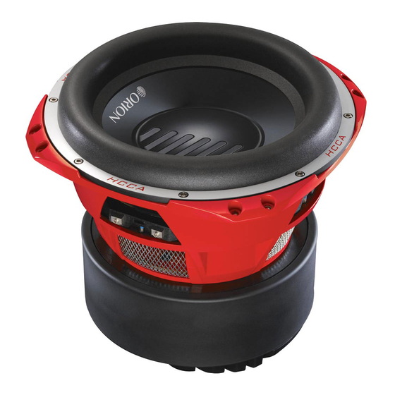
INTRODUCTION Thank you for your purchase of the Orion HCCA subwoofers. These woofers represent a combination of incredible performance and value. The HCCA series subwoofers feature a massive 4” voice coil and triple stacked magnet assembly to maximize excursion and output. Capable of maintaining their balance at exceptionally high output levels. -
Page 4: Installation
INSTALLATION The performance of these HCCA subwoofers is directly proportional to the quality of installation. Care taken during the installation process will be rewarded with years of satisfying performance. If you are unsure about your installation capabilities, please refer to your local Authorized Orion Dealer for technical assistance. Orion dealers are trained professionals dedicated to extracting the maximum performance out of your Orion system. - Page 5 Polypropylene dust cap - moisture and UV resistant. Tall, wide, balanced, NBR Foam (high density expanded polyester foam) surround for linear controlled long excursion using a Tri Radius symmetrical edge design optimized on non-linear FEA. Paper cone - moisture and UV resistant. Custom Cast Aluminum frame.
-
Page 6: Re-Cone Kit
RE-CONE KIT A re-cone kit is available for these speakers and can be obtained from your dealer. The part number for each model is listed below. Model/part # HCCA102ck HCCA104ck HCCA122ck HCCA124ck HCCA152ck HCCA154ck WIRING CONFIGURATIONS The following illustrations provide guidelines on properly connecting your HCCA Orion woofer to an Orion amplifier for maximum power and performance using Recommended Amplifier Power 1 woofer... -
Page 7: Series-One Speaker (Dual 2 Ohm Voice Coils)
Series—One Speaker (dual 2 ohm voice coils) One dual 2 ohm voice coil woofer with voice coils in connected in series results in a 4 ohm load to the amplifier. Figure 2 Figura 2 Abbildung 2 1. Connect the woofer in series by connecting the negative (-) of one terminal to the positive (+) terminal of the other coil. -
Page 8: Parallel-One Speaker (Dual 2 Ohm Voice Coils)
Parallel—One Speaker (dual 2 ohm voice coils) One dual 2 ohm voice coil woofer with voice coils in parallel results in a 1 ohm load to the amplifier. Figure 3 Figura 3 Abbildung 3 1. Connect the speaker in parallel by connecting the two positive (+) terminals together and the two negative (-) terminals together. -
Page 9: Parallel-One Speaker (Dual 4 Ohm Voice Coils)
Parallel—One Speaker (dual 4 ohm voice coils) One dual 4 ohm voice coil woofer with voice coils in parallel results in a 2 ohm load to the amplifier. Figure 4 Figura 4 Abbildung 4 1. Connect the speaker in parallel by connecting the two positive (+) terminals together and the two negative (-) terminals together. -
Page 10: Parallel-Two Speakers (Dual 4 Ohm Voice Coils)
Parallel—Two Speakers (dual 4 ohm voice coils) Two dual 4 ohm voice coil woofers with voice coils in parallel and the two woofers in parallel results in a 1 ohm load to the amplifier. Figure 5 Figura 5 Abbildung 5 1. -
Page 11: Series-Parallel-Two Speakers (Dual 2 Ohm Voice Coils)
Series-Parallel—Two Speakers (dual 2 ohm voice coils) Note: Verify and ensure that the woofer wiring is connected as shown with the negative connection from the first woofer coil connected to the positive connection of the second woofer coil. Two dual 2 ohm voice coil woofers with voice coils in series and then parallel the two series woofers results in a 2 ohm load to the amplifier. -
Page 12: Series-Parallel-Three Speakers (Dual 4 Ohm Voice Coils)
Series-Parallel—Three Speakers (dual 4 ohm voice coils) Note: Verify and ensure that the woofer wiring is connected as shown with the negative connection from the first woofer coil connected to the positive connection of the second woofer coil. Three dual 4 ohm voice coil woofer with voice coils of each woofer wired in series and then parallel the three woofers for a resulting 2.67 ohms.load to the amplifier. -
Page 13: Series-Parallel-Four Speakers (Dual 4 Ohm Voice Coils)
Series-Parallel—Four Speakers (dual 4 ohm voice coils) Note: Verify and ensure that the woofer wiring is connected as shown with the negative connection from the first woofer coil connected to the positive connection of the second woofer coil. Four dual 4 ohm voice coil woofers should be wired with the voice coils on each woofer in series and then parallel the four woofers for a resulting 2 ohm load to the amplifier. -
Page 14: Series-Parallel-Four Speakers (Dual 2 Ohm Voice Coils)
Series-Parallel—Four Speakers (dual 2 ohm voice coils) Note: Verify and ensure that the woofer wiring is connected as shown with the negative connection from the first woofer coil connected to the positive connection of the second woofer coil. Four dual 2 ohm voice coil woofers should be wired with the voice coils on each woofer in series and then parallel the four woofers for a resulting 1 ohm load to the amplifier. -
Page 15: Amplifiers-One Speaker (Dual 2 Ohm Voice Coils)
2 Amplifiers—One Speaker (dual 2 ohm voice coils) One dual 2 ohm voice coil woofer with each voice coil connected to an individual amplifier, resulting in a 2 ohm load to each amplifier. Figure 10 Figura 10 Abbildung 10 1. Connect one of the speaker’s voice coils to the first amplifier by connecting the positive (+) terminal and the negative (-) terminal from the speaker to the respective positive (+) terminal and the negative (-) terminal from the first amplifier. -
Page 16: Amplifiers-One Speaker (Dual 4 Ohm Voice Coils)
2 Amplifiers—One Speaker (dual 4 ohm voice coils) One dual 4 ohm voice coil woofer with each voice coil connected to an individual amplifier, resulting in a 4 ohm load to each amplifier. Figure 11 Figura 11 Abbildung 11 1. Connect one of the speaker’s voice coils to the first amplifier by connecting the positive (+) terminal and the negative (-) terminal from the speaker to the respective positive (+) terminal and the negative (-) terminal from the first amplifier. -
Page 17: Specifications
SPECIFICATIONS Model/Part Number Size Thiele/Small Parameters Fs (free-air resonance, Hz) Vas (equivalent compliance, cu. ft.) Vas (equivalent compliance, liters) Qms (Q, mechanical) Qes (Q, electrical) **** Qts (total driver Q) **** Re (DC resistance, ohms) **** Z (nominal impedance, ohms) Le (inductance, mh) **** Efficiency (1W @ 1M, dB) Xmax (one way linear excursion, in.) -
Page 18: Specifications
SPECIFICATIONS Model/Part Number Size Thiele/Small Parameters Fs (free-air resonance, Hz) Vas (equivalent compliance, cu. ft.) Vas (equivalent compliance, liters) Qms (Q, mechanical) Qes (Q, electrical) **** Qts (total driver Q) **** Re (DC resistance, ohms) **** Z (nominal impedance, ohms) Le (inductance, mh) **** Efficiency (1W @ 1M, dB) Xmax (one way linear excursion, in.) -
Page 19: Enclosure Details
ENCLOSURE DETAILS Parameters listed are for conventional applications only, for further help please call Tech Audio Support 1” MDF is recommended. Recommended enclosures are NET Box Volumes, speaker and port displacement are calculated into the volume of the enclosure, you will not need to add these volumes to calculate GROSS volume for the enclosure. -
Page 20: Explanation Of Enclosure Specifications
EXPLANATION OF ENCLOSURE SPECIFICATIONS There are many different factors that help determine the best style of enclosure for you or your vehicle. Listed below are some factors that should be considered. The size of the enclosure is directly proportional to the efficiency and power handling of that speaker. -
Page 21: Hcca102 & 104 Sealed Enclosure
HCCA102 & 104 Sealed Enclosure Note: These Enclosures are designed for sound quality and offer very low tuning frequencies. If you are building a system where the goal is to listen to music, these are the enclosures to build. They offer the best low frequency performance of all the designs. -
Page 22: Hcca102 & 104 Vented 800 To 1500 Watts Input
HCCA102 & 104 Vented 800 to 1500 Watts Input Note: These enclosures will deliver higher sound pressure levels than sealed enclosures. The perceived loudness will be lower than a sealed enclosure, although the metered number will be higher. WARNING: proper setting of the IntelliQ is critical or woofers may become damaged from over excursion! Box Properties —... -
Page 23: Hcca102 & 104 Vented 1500+ Watts Input
HCCA102 & 104 Vented 1500+ Watts Input Box Properties — Description — — Box Parameters — Type: Vented Box Shape: Prism, Square V(total) = Fill Top & Bottom Front Sides & Back — Vents — 0.75 cu.ft No. of Vents 1.007 cu.ft Vent shape = rectangle... -
Page 24: Hcca102 & 104 Vented Spl Enclosure Only
HCCA102 & 104 Vented SPL Enclosure Only. Note: These SPL enclosures are for dB drag vehicles only!!!!! If music is played through this type of enclosure, the woofer will be damaged! Listed here are starting points, experimentation is the key to success. Use extreme caution, the woofers can be damaged with frequencies below the tuning frequency. -
Page 25: Hcca122 & 124 Sealed Enclosures
HCCA122 & 124 Sealed Enclosures. Note: These Enclosures are designed for sound quality and offer very low tuning frequencies. If you are building a system where the goal is to listen to music, these are the enclosures to build. They offer the best low frequency performance of all the designs. -
Page 26: Hcca122 & 124 Vented 1200 To 2000 Watts Input
HCCA122 & 124 Vented 1200 to 2000 Watts Input Note: These enclosures will deliver higher sound pressure levels than sealed enclosures. The perceived loudness will be lower than a sealed enclosure, although the metered number will be higher. WARNING: proper setting of the IntelliQ is critical or woofers may become damaged from over excursion! Box Properties —... -
Page 27: Hcca122 & 124 Vented 2000+ Watts Input
HCCA122 & 124 Vented 2000+ Watts Input Box Properties — Box Parameters — — Description — Type: Vented Box V(total) = Shape: Prism, Square Fill Top & Bottom Front Sides & Back — Vents — 1.5 cu.ft No. of Vents 2.65 cu.ft Vent shape = rectangle... -
Page 28: Hcca122 & 124 Vented Spl Enclosure Only
HCCA122 & 124 Vented SPL Enclosure Only. Note: These SPL enclosures are for dB drag vehicles only!!!!! If music is played through this type of enclosure, the woofer will be damaged! Listed here are starting points, experimentation is the key to success. Use extreme caution, the woofers can be damaged with frequencies below the tuning frequency. -
Page 29: Hcca152 & 154 Sealed Enclosures
HCCA152 & 154 Sealed Enclosures. Note: These Enclosures are designed for sound quality and offer very low tuning frequencies. If you are building a system where the goal is to listen to music, these are the enclosures to build. They offer the best low frequency performance of all the designs. -
Page 30: Hcca152 & 154 Vented 1200 To 2000 Watts Input
HCCA152 & 154 Vented 1200 to 2000 Watts Input Note: These enclosures will deliver higher sound pressure levels than sealed enclosures. The perceived loudness will be lower than a sealed enclosure, although the metered number will be higher. WARNING: proper setting of the IntelliQ is critical or woofers may become damaged from over excursion! Box Properties —... -
Page 31: Hcca152 & 154 Vented 2000+ Watts Input
HCCA152 & 154 Vented 2000+ Watts Input Box Properties — Description — — Box Parameters — Type: Vented Box Shape: Prism, Square V(total) = Fill Top & Bottom Front Sides & Back — Vents — 3.05 cu.ft No. of Vents 4.491 cu.ft Vent shape = rectangle... -
Page 32: Hcca152 & 154 Vented Spl Enclosure Only
HCCA152 & 154 Vented SPL Enclosure Only. Note: These SPL enclosures are for dB drag vehicles only!!!!! If music is played through this type of enclosure, the woofer will be damaged! Listed here are starting points, experimentation is the key to success. Use extreme caution, the woofers can be damaged with frequencies below the tuning frequency. - Page 33 © 2008 Directed Electronics. All rights reserved.
-
Page 34: Français
INSTALLATION Les performances de ces haut-parleurs de graves HCCA sont directement liées à la qualité de l’installation. Les précautions prises lors de l’installation se traduiront par des années de bon fonctionnement. Si vous doutez de pouvoir obtenir une bonne installation, veuillez demander l’assistance technique d’un revendeur Orion agréé. Les revendeurs Orion sont des professionnels compétents spécialisés, capables d’obtenir les meilleures performances des systèmes Orion. - Page 35 Calotte pare-poussière en polypropylène, résistante à l’humidité et aux UV. Suspension haute, large et équilibrée en mousse NBR (mousse de polyester expansé haute densité) permettant une longue course contrôlée grâce à une conception à bord symétrique triple rayon optimisée suivant analyse non linéaire par éléments finis.
- Page 36 Anneau de serrage de la suspension, compatible avec la méthode de remplacement du cône chez l’utilisateur. (8 vis Allen) KIT DE REMPLACEMENT DU CÔNE Un kit de remplacement du cône est disponible pour ces haut-parleurs auprès des revendeurs. La référence de chaque modèle est indiquée ci-dessous. Modèle/ Description Référence...
- Page 37 Parallèle – Un haut-parleur (deux bobines mobiles de 2 ohms) Voir la figure 3 à la page 7 Un haut-parleur de graves à deux bobines mobiles de 2 ohms raccordées en parallèle constitue une charge de 1 ohm pour l’amplificateur. 1.
- Page 38 négative (-) de la première bobine à la borne positive (+) de la seconde. 2. Raccordez la borne positive (+) de la première bobine de chaque haut-parleur de graves à la borne positive (+) de l’amplificateur. Raccordez la borne négative (-) de la seconde bobine de chaque haut-parleur de graves à...
- Page 39 Quatre haut-parleurs de graves en parallèle avec pour chacun les deux bobines mobiles de 2 ohms raccordées en série constituent une charge de 1 ohm pour l’amplificateur. 1. Configurez chaque haut-parleur de graves en série en raccordant la borne négative (-) de la première bobine à la borne positive (+) de la seconde. 2.
- Page 40 SPÉCIFICATIONS Explication des caractéristiques techniques, voir les détails en pages 16 et 17 Modèle/Référence Taille Paramètres Thiele/Small Fs (résonance à l’air libre, Hz) Vas (conformité équivalente, pieds-cubes) Vas (conformité équivalente, litres) Qms (Q, mécanique) Qes (Q, électrique) **** Qts (Q total haut-parleur) **** Re (résistance c.c., ohms) **** Z (impédance nominale, ohms) Le (inductance, mH) ****...
- Page 41 DÉTAILS DU CAISSON Les paramètres indiqués ne sont valables que pour des applications conventionnelles. Pour obtenir de l’aide, veuillez téléphoner au service d’assistance technique audio. Panneau de fibres de densité moyenne de 25 mm recommandé. Les recommandations de caissons indiquent des volumes NETS. Les volumes du haut-parleur et de l’évent sont pris en compte dans le volume du caisson.
- Page 42 EXPLICATION DES CARACTÉRISTIQUES TECHNIQUES DES CAISSONS De nombreux facteurs entrent en jeu dans la détermination du meilleur type de caisson pour un utilisateur ou un véhicule donné. Voici quelques uns de ces facteurs. La taille du caisson est directement proportionnelle au rendement et à la puissance admissible du haut-parleur.
- Page 43 Explication des diagrammes de caissons clos (voir les dimensions en pages 20, 24 et Caissons clos HCCA102 & 104 Caissons clos HCCA122 & 124 Caissons clos HCCA152 & 154 Remarque : Ces caissons, conçus en vue d’une qualité de son élevée, offrent de très basses fréquences d’accord.
- Page 44 Explication des diagrammes de caissons à évent accordé (voir les dimensions en pages 21-23, 25-2 et 29-31) HCCA102 & 104 à évent accordé, entrée 800 à 1500 watts HCCA102 & 104 à évent accordé entrée de plus de 1500 watts HCCA122 &...
- Page 45 Propriétés du caisson — Description — Type : Caisson à évent accordé Forme : Prisme, carré Haut et Avant et Côtés arrière — Paramètres du caisson — — Évents — Nb d’évents = V(total) Forme évent = rectangle Extrémité évent = une affleura Hv = Wv = Remplissage...
-
Page 46: Español
INSTALACIÓN El rendimiento de estos subwoofers HCCA es directamente proporcional a la calidad de la instalación. El cuidado que se tenga durante el proceso de instalación será recompensado con muchos años de rendimiento satisfactorio. Si no está seguro de sus capacidades de instalación, pídale asistencia técnica al distribuidor autorizado local de Orion. - Page 47 Tapa de polipropileno contra el polvo; resistente a la humedad y a los rayos ultravioleta. Envolvente de espuma de Goma de Butadieno de Nitrilo (Nitrile Butadiene Rubber, NBR) alta, ancha y balanceada para grandes desplazamientos lineales controlados gracias al diseño de borde simétrico Tri Radius optimizado con Análisis de Elemento Finito (Finite Element Analysis, FEA) no lineal.
- Page 48 Anillo de abrazadera envolvente. Parte del método de unión del kit de cambio de cono en el terreno (8 tornillos de cabeza Allen). KIT DE CAMBIO DE CONO El distribuidor vende un kit de cambio de cono para estos altavoces. El número de pieza de cada modelo se indica a continuación.
- Page 49 Un woofer con 2 bobinas acústicas de 2 Ω y las bobinas acústicas en paralelo produce una carga de 1 Ω en el amplificador. 1. Conecte el woofer en paralelo conectando las dos terminales positivas (+) entre sí y las dos terminales negativas (-) entre sí. 2.
- Page 50 En serie/paralelo: tres altavoces (dos bobinas acústicas de 4 Ω cada uno) Vea la figura 7 en la página 11 Nota: Verifique y asegúrese de que el cableado del woofer es como se muestra: la terminal negativa de la bobina de un woofer conectada a la terminal positiva de la bobina del otro woofer.
- Page 51 2 amplificadores: un altavoz (dos bobinas acústicas de 2 Ω) Vea la figura 10 en la página 14 Un woofer con 2 bobinas acústicas de 2 Ω y cada bobina acústica conectada a su propio amplificador produce una carga de 2 Ω en cada amplificador. 1.
- Page 52 ESPECIFICACIONES Traducción de las especificaciones, vea las páginas 16 y 17 para más detalles Modelo / Nº de pieza Tamaño Parámetros Thiele/Small Fs (resonancia al aire libre, Hz) Vas (cumplimiento de equivalencia, pies3) Vas (cumplimiento de equivalencia, litros) Qms (Q, mecánico) Qes (Q, eléctrico)**** Qts (Q total del excitador)**** Re (resistencia CC, Ω)
- Page 53 Los parámetros indicados son sólo para aplicaciones convencionales. Si necesita más asistencia, llame a Apoyo Técnico de Sonido. Se recomienda MDF de 1 plg. de grosor. Los volúmenes de caja recomendados son NETOS. El desplazamiento del altavoz y del puerto se incluyen en el volumen de la caja. No es necesario agregarlos para calcular el volumen BRUTO de la caja.
- Page 54 Hay muchos factores que contribuyen a determinar el mejor estilo de caja para usted o su vehículo. A continuación se presentan algunos factores que se deben tener en cuenta. El tamaño de la caja es directamente proporcional a la eficiencia y el procesamiento de potencia del altavoz.
- Page 55 Traducción del diagrama de la caja sellada (las medidas se encuentran en las páginas 20, 24 y 28) Cajas selladas HCCA102 y 104 Cajas selladas HCCA122 y 124. Cajas selladas HCCA152 y 154 Nota: Estas cajas se han diseñado para producir sonido de calidad y ofrecen fre- cuencias de sintonización muy bajas.
- Page 56 Traducción del diagrama de la caja ventilada (las medidas se encuentran en las pági- nas 21-23, 25-27 y 29-31) Cajas ventiladas HCCA102 y 104 de 800 a 1500 W de entrada Cajas ventiladas HCCA122 y 124 de 1200 a 2000 W de entrada Cajas ventiladas HCCA152 y 154 de 1200 a 2000 W de entrada Cajas ventiladas HCCA102 y 104 de más de 1500 W de entrada Cajas ventiladas HCCA122 y 124 de más de 2000 W de entrada...
- Page 57 3URSLHGDGHV GH OD FDMD © 2008 directed electronics—Reservados todos los derechos.
-
Page 58: Deutsch
INSTALLATION Die Leistung dieser HCCA-Subwoofer hängt direkt von der Qualität der Installation Ein sorgfältiges Vorgehen bei der Installation garantiert Ihnen jahrelange Höchstleistungen. Wenn Sie sich nicht sicher sind, ob Sie die Installation selbst ausführen können, wenden Sie sich bitte an Ihren örtlichen Orion-Fachhändler. Orion-Händler haben ausgebildetes Fachpersonal, das aus Ihrem Orion-System das Maximum an Leistung herausholen kann. - Page 59 Feuchtigkeits- und UV-beständige Polypropylen-Abdeckung Hohe, breite, ausgeglichene Sicke aus NBR-Schaum (dichter Polyesterschaum) für linear kontrollierte, lange Auslenkung unter Verwendung eines Drei- Radius-Designs mit symmetrischen Kanten, das durch nichtlineare FEM optimiert wurde Feuchtigkeits- und UV-beständige Papiermembran Spezieller Rahmen aus Aluminiumguss Befestigungsschrauben für Zentriermembran Teil der Funktion zum Austausch der Schwingeinheit (8 Sechskantschrauben) Aluminium-Schwingspulenträger (das 10-Zoll-Modell verwendet einen 3-Zoll-Schwingspulenträger, die 12- und 15-Zoll-Modelle einen 4-Zoll-...
- Page 60 Obere verknüpfte Conex-Zentriermembran Sicken-Klemmring als Teil des Befestigungskits zum Austausch der Schwingeinheit (acht Innensechskantschrauben). KIT ZUM AUSTAUSCH DER SCHWINGEINHEIT Für diese Lautsprecher ist ein sogenannter Re-Cone-Kit zum Austausch der Schwingeinheit bei Ihrem Fachhändler erhältlich. Die Teilenummern für das jeweilige Modell finden Sie unten. Modell/ Beschreibung Teilenummer...
- Page 61 zweiten Tieftöner-Schwingspule mit dem negativen (-) Terminal am Verstärker. Parallel — Ein Lautsprecher (Doppelte 2-Ohm-Schwingspulen) Siehe Abbildung 3 auf Seite 7 Ein Tieftöner mit doppelten 2-Ohm-Schwingspulen, bei dem die Schwingspulen parallel geschaltet sind: Lastwiderstand von 1 Ohm am Verstärker. 1. Schließen Sie den Lautsprecher parallel an, indem Sie jeweils die beiden positiven (+) Terminals und die beiden negativen (-) Terminals miteinander verbinden.
- Page 62 Ohm am Verstärker. 1. Schließen Sie jeden Tieftöner in Reihe an, indem Sie das negative (-) Terminal der ersten Schwingspule mit dem positiven (+) Terminal der zweiten Spule verbinden. 2. Verbinden Sie das positive (+) Terminal der ersten Schwingspule am jeweiligen Tieftöner mit dem positiven (+) Terminal am Verstärker.
- Page 63 Reihe/Parallel — Vier Lautsprecher (doppelte 2-Ohm-Schwingspulen) Siehe Abbildung 9 auf Seite 13 Hinweis: Stellen Sie sicher, dass die Tieftöneranschlüsse wie gezeigt vorgenommen wurden, wobei der negative Anschluss an der ersten Tieftöner-Schwingspule mit dem positiven Anschluss an der zweiten Tieftöner-Schwingspule verbunden ist. Vier Tieftöner mit doppelten 2-Ohm-Schwingspulen sollten so angeschlossen werden, dass die Schwingspulen an jedem Tieftöner in Reihe geschaltet und dann die vier Tieftöner parallel geschaltet werden: Lastwiderstand von 1 Ohm am Verstärker.
- Page 64 TECHNISCHE DATEN Erklärung der Daten, Details siehe Seite 16 und 17. Modell/Teilenummer Größe Thiele/Small-Parameter Fs (Freiluftresonanz, Hz) Vas (Äquivalente Nachgiebigkeit, Kubikfuß) Vas (Äquivalente Nachgiebigkeit, Liter) Qms (Q, mechanisch) Qes (Q, elektrisch)**** Qts (totaler Treiberwert für Q)**** Re (GS-Widerstand, Ohm)**** Z (Nennimpedanz, Ohm) Le (Induktivität, mh) **** Wirkungsgrad (1 W bei 1 M, dB) Xmax (linearer Hub in eine Richtung, Zoll)
- Page 65 GEHÄUSEDETAILS Die aufgelisteten Parameter gelten nur für konventionelle Anwendungen. Um weitere Hilfe zu erhalten, rufen Sie bitte den Tech Audio Support an. Es wird empfohlen, 2,5 cm dicke Faserplatten zu verwenden. Die empfohlenen Gehäusegrößen sind NETTO-Volumen, wobei Lautsprecher- und Öffnungshub in das Gehäusevolumen einberechnet sind; Sie müssen diese Volumen nicht hinzuzählen, um das BRUTTO-Gehäusevolumen zu erhalten.
- Page 66 ERLÄUTERUNG DER GEHÄUSEDATEN Es gibt viele verschiedene Faktoren, die den besten Gehäusetyp für Sie bzw. Ihr Fahrzeug bestimmen. Unten finden Sie einige der Faktoren, die Sie in Betracht ziehen sollten. Die Gehäusegröße ist direkt proportional zum Leistungsvermögen und zur Belastbarkeit des Lautsprechers.
- Page 67 Erklärung des Diagramms für geschlossene Gehäuse (Maße finden Sie auf S. 20, 24 und 28) HCCA102 & 104 Geschlossenes Gehäuse HCCA122 & 124 Geschlossene Gehäuse HCCA152 & 154 Geschlossene Gehäuse Hinweis: Diese Gehäuse sind für die Soundqualität optimiert und bieten sehr niedrige Tuningfrequenzen.
- Page 68 Erklärung des Diagramms für Bassreflexgehäuse (Maße finden Sie auf S. 21-23, 25-27 und 29-31) HCCA102 & 104 Bassreflex, 800 bis 1500 Watt Belastbarkeit HCCA122 & 124 Bassreflex, 1200 bis 2000 Watt Belastbarkeit HCCA152 & 154 Bassreflex, 1200 bis 2000 Watt Belastbarkeit HCCA102 &...
- Page 69 *HKlXVHHLJHQVFKDIWHQ © 2008 directed electronics—Alle Rechte vorbehalten...
-
Page 70: Italiano
INSTALLAZIONE I risultati conseguibili con questi subwoofer HCCA dipendono direttamente dalla qualità dell’installazione; eseguendola con cautela si avrà la certezza di ottenere un suono soddisfacente per anni e anni. Se non si è certi di poter eseguire l’installazione correttamente, rivolgersi al rivenditore Orion, che sarà in grado di fornire l’assistenza tecnica necessaria. - Page 71 Protezione parapolvere in polipropilene - resistente all’umidità e ai raggi ultravioletti. Sospensione in schiuma NBR (schiuma di poliestere espanso ad alta densità) alta, larga e bilanciata che assicura un’escursione lunga, controllata e lineare grazie al design del bordo simmetrico Tri Radius, ottimizzato tramite analisi a elementi finiti (FEA) non lineare.
- Page 72 Gruppo anello di fissaggio-distanziatore del centratore, parte del kit di ricostruzione del cono (otto viti a testa esagonale). Centratore in Conex intrecciato piatto superiore. Anello di fissaggio della sospensione, part del kit di ricostruzione del cono (otto viti a testa esagonale). KIT DI RICOSTRUZIONE DEL CONO Per questi altoparlanti è...
- Page 73 Un diffusore in parallelo (con due bobine mobili da 2 ohm) Vedi Figura 3 a pagina 7 Un woofer con due bobine mobili da 2 ohm collegate in parallelo, applica un carico di 1 ohm all’amplificatore. 1. Collegare il woofer in parallelo collegandone tra loro i due terminali positivi (+) e i due terminali negativi (-).
- Page 74 2. Collegare il terminale positivo (+) della prima bobina di ciascun woofer al terminale positivo (+) dell’amplificatore e il terminale negativo (-) della seconda bobina di ciascun woofer al terminale negativo (-) dell’amplificatore. Tre diffusori in serie-parallelo (ciascuno con due bobine mobili da 4 ohm) Vedi Figura 7 a pagina 11 Nota: verificare che i woofer siano cablati come illustrato, con il terminale negativo della prima bobina mobile di ciascun woofer collegato al terminale...
- Page 75 terminale positivo (+) dell’amplificatore e il terminale negativo (-) della seconda bobina di ciascun woofer al terminale negativo (-) dell’amplificatore. Due amplificatori e un diffusore (con due bobine mobili da 2 ohm) Vedi Figura 10 a pagina 14 Un woofer con due bobine mobili da 2 ohm, ciascuna collegata a un amplificatore separato, applica un carico di 2 ohm a ciascun amplificatore.
- Page 76 DATI TECNICI Per i dati tecnici dettagliati vedere alle pagine 16 e 17. Modello/Codice Dimensioni Parametri Thiele/Small Fs (freq. di risonanza in aria libera, Hz) Vas (volume equivalente di cedevolezza, cu ft) Vas (volume equivalente di cedevolezza, litri) Qms (Q, meccanico) Qes (Q, elettrico) **** Qts (Q totale driver) **** Re (resistenza in c.c., ohm) ***...
- Page 77 DETTAGLI DELLA CASSA I parametri elencati sono validi solo per applicazioni convenzionali, per ulteriori informazioni rivolgersi al servizio di assistenza. Si suggerisce una cassa in MDF (pannelli di fibre a media densità) da 1” (2,54 cm). I valori suggeriti per il volume della cassa sono valori NETTI. Il volume della cassa tiene conto dei volumi dell’altoparlante e dell’apertura;...
- Page 78 SPIEGAZIONE DEI DATI TECNICI DELLA CASSA Il tipo migliore di cassa per le esigenze del proprietario o le condizioni del veicolo dipende da numerosi fattori, alcuni dei quali sono elencati di seguito. Le dimensioni della cassa sono direttamente proporzionali all’efficienza e alla potenza tollerabile dall’altoparlante;...
- Page 79 Legenda relativa alla cassa sigillata (vedi pagine 20, 24 e 28 per le misure) Cassa sigillata HCCA102 e 104 Casse sigillate HCCA122 e 124 Casse sigillate HCCA152 e 154 Nota: queste casse offrono una buona qualità del suono e frequenze di sintonizzazione molto basse.
- Page 80 Legenda relativa alla cassa ventilata (vedi pagine 21-23, 25-27 e 29-31 per le misure) Casse ventilate HCCA102 e 104 con ingresso compreso tra 800 e 1500 watt Casse ventilate HCCA102 e 124 con ingresso compreso tra 1200 e 2000 watt Casse ventilate HCCA152 e 154 con ingresso compreso tra 1200 e 2000 watt Casse ventilate HCCA102 e 104 con ingresso maggiore di 1500 watt Casse ventilate HCCA102 e 124 con ingresso maggiore di 2000 watt...
- Page 81 3URSULHW GHOOD FDVVD © 2008 directed electronics—tutti i diritti riservati...
-
Page 82: Português
PORTUGUÊS INSTALAÇÃO O desempenho dos subwoofers HCCA é diretamente proporcional à qualidade da instalação. O cuidado durante o processo de instalação será recompensado com anos de satisfação com o desempenho. Caso não esteja certo quanto à sua capacidade para fazer a instalação, consulte o revendedor autorizado local da Orion para obter assistência técnica. - Page 83 Cobertura contra pó de polipropileno resistente à umidade e radiação ultravioleta. Surround de espuma de borracha nitrílica (NBR, espuma de poliéster expandida de alta densidade) grande, larga e balanceada para deslocamento linear longo controlado usando um design de borda simétrica tri-radial otimizada em análise FEA não linear.
- Page 84 KIT DE TROCA DE CONE Há um kit de troca de cone disponível para estes alto-falantes que pode ser obtido junto ao revendedor. O número da peça de cada modelo está descrito abaixo. Modelo/número Descrição da peça HCCA102ck Kit de troca de cone ORION HCCA 10” de 2 OHM HCCA104ck Kit de troca de cone ORION HCCA 10”...
- Page 85 Um woofer com duas bobinas móveis de 2 ohm conectadas em paralelo resulta em uma carga de 1 ohm ao amplificador. 1. Conecte o alto-falante em paralelo unindo os dois terminais positivos (+) juntos e os dois terminais negativos (-) juntos. 2.
- Page 86 Série-Paralela – Três alto-falantes (duas bobinas de 4 ohm) Ver figura 7 na página 11 Nota: Verifique e certifique-se de que os cabos dos woofers estejam conectados como mostrado, com o terminal negativo da bobina do primeiro woofer conectado ao terminal positivo da bobina do segundo woofer. Três woofers com duas bobinas móveis de 4 ohm com as bobinas de cada woofer conectadas em série e em seguida os três woofers em paralelo resultam em uma carga de 2,67 ohm ao amplificador.
- Page 87 Dois amplificadores – Um alto-falante (duas bobinas de 2 ohm) Ver figura 10 na página 14 Um woofer com duas bobinas móveis de 2 ohm com cada bobina conectada a um amplificador, resultando em uma carga de 2 ohm a cada amplificador. 1.
- Page 88 ESPECIFICAÇÕES Tradução das especificações, ver detalhes nas páginas 16 e 17. Modelo/Número do produto Tamanho Parâmetros Thiele/Small Fs (ressonância ao ar livre, Hz) Vas (conformidade equivalente, pés cúbicos) Vas (conformidade equivalente, litros) Qms (Q, mecânica) Qes (Q, elétrica) **** Qts (Q total do alto-falante) **** Re (resistência à...
- Page 89 DETALHES DA CAIXA Os parâmetros especificados são apenas para aplicações convencionais. Para obter mais ajuda, ligue para o grupo de suporte técnico de áudio. MDF de 2,5 cm (1”) recomendado. Os volumes das caixas recomendadas são volumes LÍQUIDOS. O deslocamento do alto-falante e do duto estão incluídos no volume da caixa.
- Page 90 EXPLICAÇÃO DAS ESPECIFICAÇÕES DAS CAIXAS Existem muitos fatores diferentes que ajudam a determinar o melhor estilo de caixa para o usuário ou o veículo. Estes são alguns fatores que devem ser considerados: O tamanho da caixa é diretamente proporcional à eficiência e à potência máxima permissível do alto-falante.
- Page 91 Tradução do diagrama da caixa selada (ver as medidas nas páginas 20, 24 e 28) Caixas seladas HCCA102 e 104 Caixas seladas HCCA122 e 124 Caixas seladas HCCA152 e 154 Nota: Essas caixas são projetadas para maximizar a qualidade do som e propor- cionar freqüências de sintonização bem baixas.
- Page 92 Tradução do diagrama da caixa ventilada (ver as medidas nas páginas 21-23, 25-27 e 29-31) Ventiladas HCCA102 e 104 com entrada de 800 a 1500 W Ventiladas HCCA102 e 104 com entrada de 1500+ W Ventiladas HCCA122 e 124 com entrada de 1200 a 2000 W Ventiladas HCCA122 e 124 com entrada de 2000+ W Ventiladas HCCA152 e 154 com entrada de 1200 a 2000 W Ventiladas HCCA152 e 154 com entrada de 2000+ W...
- Page 93 3URSULHGDGHV GD FDL[D © 2008 directed electronics—Todos os direitos reservados...
-
Page 94: Warranty
WARRANTY LIMITED ONE-YEAR CONSUMER WARRANTY/*LIMITED TWO-YEAR CONSUMER WARRANTY FOR AUTHORIZED DIRECTED DEALER PURCHASE & INSTALLATION Directed Electronics (herein “Directed”) promises to the original purchaser of the subwoofer or amplifier, as applicable (herein “Unit” or “Product”), to repair or replace with a new or refurbished Unit (at Directed’s sole and absolute discretion) should the Unit prove to be defective in workmanship or material under normal use, for a period of *two-years from the date of purchase from the authorized Directed dealer PROVIDED the Unit was purchased and installed by an authorized Directed dealer.