Advertisement
Quick Links
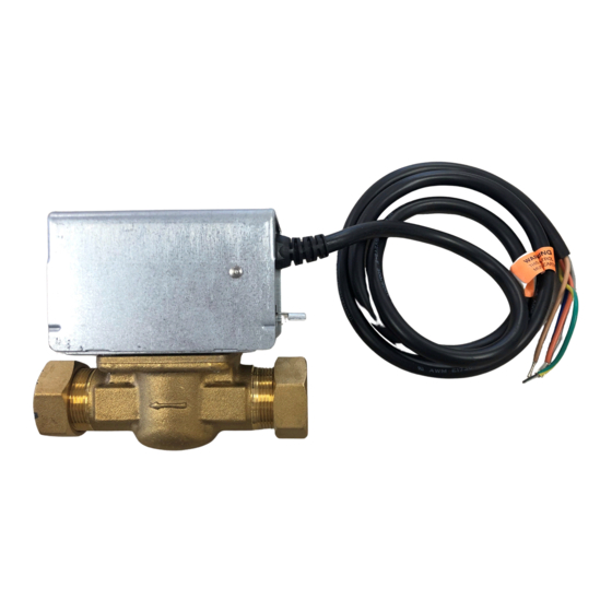
V4043, V4044 Valves;
V8043, V8044 Zone Valves
APPLICATION
These valves consist of an actuator motor and valve
assembly for controlling the flow of hot and/or cold water.
The V4043 and V8043 provide two-position, straight-
through control of supply water. The V4044 and V8044
provide two-position, diverting control of supply water.
The valves are designed for use with fan coil and other
units requiring quiet, compact water valves. The V8043E
and F also control supply water for baseboard radiators
and convectors. The V4043E and V8043J provide
straight-through control of steam only. Models are
available with 125 or 300 psi operating pressure.
INSTALLATION
When Installing this Product...
1. Read these instructions carefully. Failure to follow
them could damage the product or cause a hazard-
ous condition.
2. Check the ratings given in the instructions and on
the product to make sure the product is suitable for
your application.
3. Installer must be a trained, experienced service
technician.
4. After installation is complete, check out product
operation as provided in these instructions
CAUTION
1.
Disconnect power supply before connecting
wiring to prevent electrical shock of equip-
ment damage.
2.
Normally it is not necessary to remove the
powerhead from the valve body during instal-
lation. If the valve must be disassembled, be
certain that it is reassembled with the water
INSTALLATION INSTRUCTIONS
flow in the direction of the arrow. Reversal of
the powerhead will result in damage to the
gear train.
3.
On 24V systems, never jumper the valve coil
terminals even temporarily. This may burn
out the heat anticipator in the thermostat.
IMPORTANT
Use this valve in hydronic heating systems
which do not contain dissolved oxygen in the
system water. The dissolved oxygen, which is
found in systems that have a frequent source of
makeup water, causes the rubber plug inside
the valve to deteriorate and eventually fail.
LOCATION
Install the valve in an area with adequate clearance to:
— Move the manual opening lever on the side of the
powerhead.
— Remove the powerhead cover.
— Wire the powerhead.
— Replace the powerhead motor.
The valve location should be in an area where the
temperature does not exceed the maximum valve
operating temperature as shown in Fig. 1. The maximum
valve operating temperature depends on the maximum
ambient temperature at the valve location and the
maximum fluid temperature. Using the graph in Fig. 1,
the maximum valve operating temperature can be found
as follows:
1. Measure ambient temperature at valve and locate
this temperature on the ambient temperature scale
on the graph.
2. Draw a line from this ambient temperature, parallel
with the fluid temperature scale, to the maximum
fluid temperature line.
3. Draw a line from this point down to the fluid temp-
erature scale to find maximum operating tempera-
ture. (Note the example, shown by the dashed line
in Fig. 1).
Place Bar Code Here
95-6983-11
Advertisement

Related Manuals for Honeywell V4043


Summary of Contents for Honeywell V4043
-
Page 1: Installation Instructions
On 24V systems, never jumper the valve coil assembly for controlling the flow of hot and/or cold water. terminals even temporarily. This may burn The V4043 and V8043 provide two-position, straight- out the heat anticipator in the thermostat. through control of supply water. The V4044 and V8044 provide two-position, diverting control of supply water. - Page 2 V4043, V4044 VALVES; V8043, V8044 ZONE VALVES MAXIMUM AMBIENT TEMPERATURE LINE (99) (93) (88) (82) MAXIMUM FLUID TEMPERATURE LINE (77) (71) (66) EXAMPLE: 150°F (66°C) IS THE AMBIENT TEMPERATURE AT THE VALVE, 235F (113C) IS MAXIMUM FLUID TEMPERATURE. (60) (54)
- Page 3 V4043, V4044 VALVES; V8043, V8044 ZONE VALVES 3. IMPORTANT: Take care not to burn the plastic por- 1. Disconnect the power supply before connecting the tion of the composite adapter plate when soldering. wiring to prevent electrical shock or equipment 4.
- Page 4 V4043, V4044 VALVES; V8043, V8044 ZONE VALVES c. Secure the powerhead to the valve body with the two screws provided. HEX-NUT SCREW d. If fitted, reconnect the conduit or cable. Recon- WITH DOMED HEADS (2) nect the leadwires at the powerhead.
- Page 5 V4043, V4044 VALVES; V8043, V8044 ZONE VALVES COVER RETAINING SCREW MANUAL OPENING LEVER M10161 Fig. 7. Remove old powerhead cover from systems using new style valve bodies. 4. Install the new powerhead (see Fig. 6): a. Place the manual opening lever (normally...
- Page 6 V4043, V4044 VALVES; V8043, V8044 ZONE VALVES T822 T822 T822 T822 T822 T822 (HOT) (HOT) V8043A V8043A V8043A V8043E V8043E V8043E POWER SUPPLY. PROVIDE DISCONNECT MEANS AND OVERLOAD PROTECTION AS REQUIRED. CONNECT V8043A BLACK LEADWIRE TO THERMOSTAT. M10168 Fig. 10. T822 thermostat, V8043A valve hookup.
- Page 7 M10163 AND OVERLOAD PROTECTION AS REQUIRED. M5958 Fig. 18. Wiring a Honeywell V8043E to a Taco System. Fig. 17. Existing Taco System. (Wires are identified by (Wires are identified by letters for easy letters for easy correspondence to wires on Figs. 18 &...
- Page 8 THERMOSTAT OVERLOAD PROTECTION AS REQUIRED. M5966 POWER SUPPLY. PROVIDE DISCONNECT MEANS AND Fig. 22. Wiring a Honeywell V8043F to a Dole system OVERLOAD PROTECTION AS REQUIRED. (2 options). (Wires are identified by letters for easy M5960 correspondence to wires on Fig. 20.) Fig.
- Page 9 IF TRANSFORMER SUPPLIES POWER TO AUXILIARY CIRCUIT, WIRE AUXILIARY CIRCUIT AS SHOWN IN LOWER DIAGRAM. Fig. 25. Wiring a Honeywell V8043F to a Flair System TAPE UNUSED END AND TUCK INTO HOLE. (2 options). (Wires are identified by letters for easy M5713 correspondence to wires on Fig.