Panasonic KX-NCP500 Installation Manual
Hide thumbs
Also See for KX-NCP500:
- Programming manual (1016 pages) ,
- Pc programming manual (892 pages) ,
- Features manual (504 pages)
Table of Contents
Advertisement
Quick Links
Installation Manual
Pure IP-PBX
KX-NCP500
Model No.
KX-NCP1000
Thank you for purchasing a Panasonic Pure IP-PBX.
Please read this manual carefully before using this product and save this manual for future use.
SD Logo is
KX-NCP500/KX-NCP1000: PBMPR Software File Version 5.0000 or later
a trademark of
SD-3C, LLC.
Advertisement
Table of Contents
Troubleshooting

Related Manuals for Panasonic KX-NCP500


Summary of Contents for Panasonic KX-NCP500
-
Page 1: Installation Manual
Thank you for purchasing a Panasonic Pure IP-PBX. Please read this manual carefully before using this product and save this manual for future use. SD Logo is KX-NCP500/KX-NCP1000: PBMPR Software File Version 5.0000 or later a trademark of SD-3C, LLC. -
Page 2: System Components
System Components System Components System Components Table Category Model No. Description Main Unit KX-NCP500 Main Unit KX-NCP1000 Main Unit Main Processing Card IP Convergence Main Processing Card (IPCMPR) IPCMPR Option Cards KX-NCP1104 4-Channel VoIP DSP Card (DSP4) KX-TDE0110 16-Channel VoIP DSP Card (DSP16) - Page 3 System Components Category Model No. Description KX-NCS2205 Activation Key for CA PRO for 5 Users (CA Pro 5users) KX-NCS2210 Activation Key for CA PRO for 10 Users (CA Pro 10users) KX-NCS2240 Activation Key for CA PRO for 40 Users (CA Pro 40users) KX-NCS2249 Activation Key for CA PRO for 128 Users (CA Pro...
- Page 4 KX-T7765 Note that the types of activation keys are subject to change without notice. For CA activation keys, refer to the documentation for Equipment Compatibility Compatible Panasonic Proprietary Telephones The PBX supports the following telephones: • IP proprietary telephones (e.g., KX-NT300 series)
-
Page 5: List Of Abbreviations
• Some optional hardware, software, and features are not available in some countries/areas, or for some PBX models. Please consult your certified Panasonic dealer for more information. • In this manual, the suffix of each model number (e.g., KX-NCP500NE) is omitted unless necessary. -
Page 6: Safety Notices
Safety Notices Safety Notices Please observe the safety notices in this manual in order to avoid danger to users or other people, and prevent damage to property. The notices are classified as follows, according to the severity of injury or damage: This notice means that misuse could result in death WARNING or serious injury. -
Page 7: Important Information
Important Information Important Information SAVE THESE INSTRUCTIONS WARNING SAFETY REQUIREMENTS For All Telephone Equipment • Do not install the product in any other way than described in relevant manuals. • The product must only be installed and serviced by qualified service personnel. The product should be used as-is from the time of purchase;... - Page 8 Unplug this unit from the AC outlet if it emits smoke, an abnormal smell or makes unusual noise. These conditions can cause fire or electric shock. Confirm that smoke has stopped and contact an authorised Panasonic Factory Service Centre. •...
- Page 9 Contact your telephone company. If all SLTs operate properly, there may be a problem with your PBX. Do not reconnect the PBX to the trunks until it has been serviced by an authorised Panasonic Factory Service Centre Installation Manual...
-
Page 10: Important Safety Instructions
Important Safety Instructions Important Safety Instructions When using your telephone equipment, basic safety precautions should always be followed to reduce the risk of fire, electric shock and injury to persons, including the following: • Do not use the product near water, for example, near a bathtub, wash bowl, kitchen sink, or laundry tub, in a wet basement, or near a swimming pool. - Page 11 A replacement fuse cover can be purchased from your local Panasonic dealer. IF THE FITTED MOULDED PLUG IS UNSUITABLE FOR THE AC OUTLET IN YOUR PREMISES, THEN THE FUSE SHOULD BE REMOVED AND THE PLUG CUT OFF AND DISPOSED OF SAFELY.
- Page 12 Precaution During dialling, this apparatus may tinkle the bells of other telephones using the same line. This is not a fault and we advise you not to call the Fault Repair Service. For users in the European Union only Information for Users on Collection and Disposal of Old Equipment and used Batteries These symbols on the products, packaging, and/or accompanying documents mean that used electrical and electronic products and batteries should not be mixed with general household waste.
- Page 13 Precaution that any item will work correctly in all respects with another item of Telepermitted equipment of a different make or model, nor does it imply that any product is compatible with all of Telecom's network services. • This equipment is not capable, under all operating conditions, of correct operation at the higher speeds for which it is designed.
- Page 14 Introduction Introduction This Installation Manual is designed to serve as an overall technical reference for the Panasonic Pure IP-PBX, KX-NCP500/KX-NCP1000. It provides instructions for installing the hardware, and programming the PBX using the Maintenance Console. The Structure of this Manual...
-
Page 15: Table Of Contents
Table of Contents Table of Contents 1 System Outline ..................17 Basic System Construction ...................18 1.1.1 Main Unit ........................18 1.1.2 System Connection Diagram ..................19 Optional Equipment ......................21 1.2.1 Optional Equipment ......................21 Specifications ........................23 1.3.1 General Description ......................23 1.3.2 Characteristics ........................25 1.3.3 System Capacity ......................26 2 Activation Key Installation ..............35 Information about the Activation Keys .................36... - Page 16 Table of Contents 3.7.2 DPH4 Card (KX-TDA0161) ....................90 3.7.3 DPH2 Card (KX-TDA0162) ....................92 3.7.4 EIO4 Card (KX-TDA0164) ....................95 3.7.5 ECHO16 Card (KX-TDA0166) ..................98 3.7.6 MSG4 Card (KX-TDA0191) ....................99 3.7.7 ESVM2 Card (KX-TDA0192) and ESVM4 Card (KX-TDA0194) ........100 Connection of Extensions ....................101 3.8.1 Maximum Cabling Distances of the Extension Wiring (Twisted Cable) ......101 3.8.2...
-
Page 17: System Outline
Section 1 System Outline This section provides general information on the PBX, including the system capacity and specifications. Installation Manual... -
Page 18: Basic System Construction
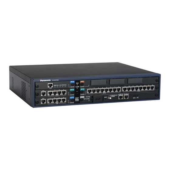
1.1.1 Main Unit 1.1 Basic System Construction 1.1.1 Main Unit The main unit contains a power supply unit (PSU) and an IPCMPR card for starting and controlling the PBX. KX-NCP500 KX-NCP1000 Construction of the Main Unit IPCMPR Card KX-NCP500 KX-NCP1000... -
Page 19: System Connection Diagram
1.1.2 System Connection Diagram 1.1.2 System Connection Diagram Private ITSP IP Network Network Trunk (Telephone Company Lines) Analogue/BRI/PRI/T1/E1 Remote PC Router (e.g., ADSL Modem) Pure IP-PBX IP-PT IP Softphone, CA Client PC Fax Machine SIP Extension DSS Console Printer Wireless Phone IP-CS ISDN Telephone External Sensor/... - Page 20 1.1.2 System Connection Diagram Analogue LCOT4 SLC16 (KX-NCP1180) Trunk (KX-NCP1174) SLC8 ISDN BRI Line BRI2 (KX-NCP1173) (KX-NCP1280) (Digital Trunk) Wireless Phone Fax Machine DLC16 PRI30 (KX-NCP1290CE/ (KX-NCP1172) Telephone ISDN PRI Line KX-NCP1290CJ/ Company (Digital Trunk) DLC8 KX-DT346/ KX-NCP1290CN) (KX-NCP1171) KX-DT300/ KX-DT300/ KX-DT343/ PRI23...
-
Page 21: Optional Equipment
1.2.1 Optional Equipment 1.2 Optional Equipment 1.2.1 Optional Equipment Model No. Model Name Description KX-NCP1104 4-Channel VoIP DSP Card (DSP4) 4-channel digital signal processor card with a 4-Channel IP Trunk activation key and an 8-Channel IP Proprietary Telephone activation key preinstalled. Compliant with ITU-T G.729A and G.711 codec methods. - Page 22 1.2.1 Optional Equipment Model No. Model Name Description KX-TDA0162 2-Port Doorphone Card (German 2-port doorphone card for 2 German-type Type) (DPH2) doorphones and 2 door openers. To be mounted on the OPB3 card. KX-TDA0164 4-Port External Input/Output Card 4-port external input/output card. To be mounted (EIO4) on the OPB3 card.
-
Page 23: Specifications
H.100 bus conformity (1024 time slots) Switching Non-blocking Power Input KX-NCP500 100 V AC to 130 V AC; 1.0 A/200 V AC to 240 V AC; 0.6 A; 50 Hz/60 Hz KX-NCP1000 100 V AC to 130 V AC; 1.3 A/200 V AC to 240 V AC; 0.8 A; 50... - Page 24 DSS Console and Add-on Key 1-pair wire (D1, D2) Module 430 mm (W) ´ 88 mm (H) ´ 340 mm (D) Dimension KX-NCP500 430 mm (W) ´ 130 mm (H) ´ 340 mm (D) KX-NCP1000 Weight (when fully KX-NCP500 Under 7 kg...
-
Page 25: Characteristics
1.3.2 Characteristics 1.3.2 Characteristics Terminal Equipment Loop Limit • PT: KX-DT300/KX-T7600 series DPT: 90 W; all other DPTs/APTs: 40 W • SLT: 600 W including set Doorphone: 20 W • • CS: 65 W 15 000 W minimum Minimum Leakage Resistance Maximum Number of Extension for PT or SLT Instruments per Line... -
Page 26: System Capacity
1.3.3 System Capacity 1.3.3 System Capacity Type and Maximum Number of Slots The PBX supports the following type and number of slots. Maximum Number Slot Type KX-NCP500 KX-NCP1000 IPCMPR Card Slot Regular Free Slot Small Free Slot Virtual Trunk Slot... - Page 27 1.3.3 System Capacity Virtual Slots of the IPCMPR Card Example: Virtual Slots of the KX-NCP1000 Virtual Extension Slots IPCMPR Card Virtual Trunk Slots Virtual Slots Installation Manual...
- Page 28 When the PBX starts up with an invalid configuration, some cards will be ignored. Cards Installed in Free Slots or Virtual Slots : For Small Free Slots : For Regular Free Slots Maximum Number Card Type KX-NCP500 KX-NCP1000 IPCMPR Trunk Card Virtual Trunk Card V-IPGW16...
- Page 29 1.3.3 System Capacity Cards Mounted on Other Optional Service Cards Maximum Number Card Type Mounted on KX-NCP500 KX-NCP1000 DSP4 DSP16 IPCMPR Card DSP64 DPH4 DPH2 ECHO16 MSG4 OPB3 Card ESVM2 ESVM4 EIO4 Only 1 ECHO16 card can be mounted on each OPB3 card.
- Page 30 1.3.3 System Capacity DSP Card Resources The maximum number of simultaneous calls using IP protocols is determined by the type of call, codec(s) used, and digital signal processor (DSP) card installed in the PBX. Below are some example configurations and the maximum number of simultaneous calls for each. For Calls between Virtual Trunks and Virtual Extensions Maximum Number of Simultaneous Calls Codec(s) Used...
- Page 31 One 8-channel PT-interface CS or IP-CS counts as 2 CSs, up to a maximum of 32 CSs. Therefore, the maximum number of CSs is 21 (eleven 2-channel CSs + ten 8-channel CSs). For the KX-NCP500, when using the DPH2 card, the maximum number of doorphones is 12. Installation Manual...
- Page 32 1.3.3 System Capacity Note for KX-NT265 IP-PT users The supported card varies depending on the software version of your KX-NT265 IP-PT. To confirm the version, follow the procedure below: While starting up SP-PHONE SP-PHONE PROGRAM "AP Version". Select Select "Maintenance". "Version display".
- Page 33 1.3.3 System Capacity Power Supply Unit Capacity The pre-installed power supply unit (PSU) in each PBX supports a different load figure. PBX Model Maximum Load Figure KX-NCP500/KX-NCP1000 Load Figure Calculation Equipment Type Load Figure KX-DT300 series DPT/KX-DT300 series DSS console/KX-T7600 series DPT/KX-T7600 series...
- Page 34 1.3.3 System Capacity Required Card Lines and Equipment Load Figure Small Free Regular Virtual Slot Slot Free Slot Extension KX-DT300 24 units DLC16 – series DPT DHLC4 16 units SLC16 – KX-NT300 V-IPEXT32 40 units – – ´ 2 series IP-PT –...
-
Page 35: Activation Key Installation
Section 2 Activation Key Installation This section describes information on activation keys, including how to obtain an activation key and install it in the SD Memory Card. Installation Manual... -
Page 36: Information About The Activation Keys
2.1.1 Activation Keys 2.1 Information about the Activation Keys 2.1.1 Activation Keys To use IP trunks and IP telephones on a private IP network using the IPCMPR card or to upgrade the software for enhanced features, you need the appropriate activation keys. Activation keys are provided via the DSP cards and optional activation key files. - Page 37 2.1.1 Activation Keys Maximum Supported IP Trunks/IP Activation Key Type Description Number Telephones/CA Users Allows the use of CA ACD Monitor CA Supervisor 1user 4 users for 1 ICD Supervisor. Upgrades software to use enhanced Software Upgrade 01 features. You need to set the number of the installed activation key to be used for H.323 trunks through system programming. By default, all the installed activation keys will be used for SIP trunks.
- Page 38 2.1.1 Activation Keys Activation Keys for IP Trunks Maximum Number/Supported IP Trunks Model No. Activation Key Type with DSP4/DSP16 with DSP64 KX-NCS3102 2 IP Trunk 60 IP trunks 48 IP trunks (H.323/SIP) (H.323/SIP) KX-NCS3104 4 IP Trunk Activation Keys for IP Telephones Maximum Number/Supported IP Telephones Model No.
- Page 39 2.1.1 Activation Keys Activation Key for Software Upgrading Model No. Activation Key Type Maximum Number KX-NCS3910 Software Upgrade 01 Note • For information about how to obtain the additional activation keys, refer to "2.1.2 Activation Key Code and Key Management System". •...
-
Page 40: Activation Key Code And Key Management System
2.1.2 Activation Key Code and Key Management System 2.1.2 Activation Key Code and Key Management System To obtain additional activation keys, you need to purchase the appropriate activation key codes and access the Key Management System. You can download the activation keys as an activation key file from the Key Management System. -
Page 41: Activation Key File
2.1.3 Activation Key File 2.1.3 Activation Key File The corresponding number of IP trunks and IP telephones or enhanced features can be activated by installing the downloaded activation key file(s) in the SD Memory Card of the IPCMPR card using the Maintenance Console. - Page 42 2.1.3 Activation Key File Installation Manual...
-
Page 43: Installation
Section 3 Installation This section describes the procedures to install the PBX. Detailed instructions for planning the installation site, installing the main unit and optional service cards, and cabling of peripheral equipment are provided. Further information on peripheral equipment installation is included. -
Page 44: Before Installation
3.1.1 Before Installation 3.1 Before Installation 3.1.1 Before Installation Please read the following notes concerning installation and connection before installing the PBX and terminal equipment. Be sure to comply with all applicable laws, regulations, and guidelines. Safety Installation Instructions WARNING When installing telephone wiring, basic safety precautions should always be followed to reduce the risk of fire, electric shock and injury to persons, including the following: •... -
Page 45: Wiring Precautions
3.1.1 Before Installation Wiring Precautions Be sure to follow these instructions when wiring the unit: CAUTION • Avoid using the same AC outlet for computers, telexes, and other office equipment, as noise generated by such equipment may hamper system performance or interrupt the system. •... -
Page 46: Installation Of The Pbx
3.2.1 Unpacking 3.2 Installation of the PBX 3.2.1 Unpacking Unpack the box and check the items below: KX-NCP500 KX-NCP1000 Main Unit Ferrite Core (for the IPCMPR card) AC Cord 19-inch Rack Attachment Bracket SD Memory Card Screw KX-NCP500BX/KX-NCP1000BX is supplied with 2 types of AC cord. Please use whichever is appropriate for the country/area. -
Page 47: Names And Locations
3.2.2 Names and Locations 3.2.2 Names and Locations KX-NCP500 Front Back KX-NCP1000 Front Back Small Free Slots RUN Indicator Regular Free Slots ALARM Indicator IPCMPR Card Slot MNT Port LAN Port Hook Clip Power Switch AC Inlet Earth Terminal RS-232C Port Note A Power Supply Unit (PSU) is pre-installed. -
Page 48: Frame Earth Connection
3.2.3 Frame Earth Connection 3.2.3 Frame Earth Connection Loosen the screw. Insert an earthing wire (user-supplied). Screw Tighten the screw. Earthing wire Connect the earthing wire to earth. To earth WARNING • Proper earthing (connection to earth) is very important to reduce the risk to the user of electrocution or to protect the PBX from the bad effects of external noise in the case of a lightning strike. -
Page 49: Installing/Removing The Optional Service Cards
3.2.4 Installing/Removing the Optional Service Cards 3.2.4 Installing/Removing the Optional Service Cards CAUTION • To protect the back board from static electricity, do not touch parts on the back board in the main unit and on the optional service cards. To discharge static electricity, touch ground or wear an earthing strap. - Page 50 3.2.4 Installing/Removing the Optional Service Cards Turn the 2 screws clockwise to fix the card in place. Screws To remove the card, reverse the procedure above. Note Make sure the screws are tightened to earth the card securely. Installation Manual...
-
Page 51: Types Of Connectors
3.2.5 Types of Connectors 3.2.5 Types of Connectors Connector Type Pin Number Used for • IPCMPR RJ45 • DHLC4 (KX-NCP1170) • DLC8 (KX-NCP1171) • DLC16 (KX-NCP1172) • SLC8 (KX-NCP1173) • SLC16 (KX-NCP1174) • LCOT4 (KX-NCP1180) • T1 (KX-NCP1187) • E1 (KX-NCP1188) (Twisted pair cable) •... - Page 52 3.2.5 Types of Connectors Connector Type Pin Number Used for • IPCMPR Mini Plug Installation Manual...
-
Page 53: Attaching A Ferrite Core
3.2.6 Attaching a Ferrite Core 3.2.6 Attaching a Ferrite Core A ferrite core must be attached when an RJ45 connector is connected to an IPCMPR or E1/PRI30/BRI2 cards. For the IPCMPR Card Wrap the cable once around the ferrite core, then close the case of the ferrite core. Attach the ferrite core 3 cm away from the connector. -
Page 54: 19-Inch Rack Mounting
3.2.7 19-inch Rack Mounting 3.2.7 19-inch Rack Mounting WARNING • Be careful not to drop any components. Dropping components may damage them or cause an injury. • Only use the 19-inch rack mounting equipment (attachment bracket, screws) included with the PBX. -
Page 55: Floor Standing
3.2.8 Floor Standing 3.2.8 Floor Standing When installing the PBX on the floor, make sure to follow these instructions. WARNING Be careful not to drop any components. Dropping components may damage them or cause an injury. CAUTION • Make sure that the PBX is placed as indicated in the diagram below. Do not place it on its side or upside down. -
Page 56: Surge Protector Installation
3.2.9 Surge Protector Installation 3.2.9 Surge Protector Installation CAUTION Performing surge protection is essential. Make sure to follow the instructions in this section. Overview A massive electrical surge can be caused if lightning strikes a telephone cable 10 m above ground, or if a telephone line comes into contact with a power line. - Page 57 3.2.9 Surge Protector Installation Outside Installation (Main Building) Surge Protector Trunk (Another Building) Trunk Extn. PT-interface CS Terminal Board Surge Extn. Protector Extn. Extn. PT-interface CS Earth Extn.: Extension Line If you install an extension outside of the building, the following precautions are recommended: Install the extension wire underground.
- Page 58 3.2.9 Surge Protector Installation Connect the earth rod to the surge protector using an earthing wire with a cross-sectional area of at least 1.3 mm Bury the earth rod near the protector. The earthing wire should be as short as possible. The earthing wire should run straight to the earth rod.
-
Page 59: Information About The Main Processing Card
3.3.1 IPCMPR Card 3.3 Information about the Main Processing Card 3.3.1 IPCMPR Card Function The IPCMPR card is the preinstalled main processing card with built-in ESVM card feature (2-channel). The Virtual Cards (trunk/extension) can be installed in Virtual Slots of the IPCMPR card and can be activated with the activation keys. - Page 60 3.3.1 IPCMPR Card • For details about connecting to a LAN, refer to "3.11 LAN Connection" • For details about connecting peripherals, refer to "3.10.1 Connection of Peripherals" • For details about System Initialise Switch, refer to "3.13.1 Starting the PBX". •...
- Page 61 3.3.1 IPCMPR Card Indication Colour Description 10BASE-T/ 2 LINK Green Link status indication 100BASE-TX • OFF: Off-line • ON: Linked normally • Flashing: In communication Yellow Data transmission speed indication • OFF: 10 Mbps • ON: 100 Mbps 1 LINK Green Link status indication •...
-
Page 62: Dsp4 Card (Kx-Ncp1104), Dsp16 Card (Kx-Tde0110), And Dsp64 Card (Kx-Tde0111)
3.3.2 DSP4 Card (KX-NCP1104), DSP16 Card (KX-TDE0110), and DSP64 Card (KX-TDE0111) 3.3.2 DSP4 Card (KX-NCP1104), DSP16 Card (KX-TDE0110), and DSP64 Card (KX-TDE0111) Function DSP4: 4-channel digital signal processor card with a 4-Channel IP Trunk activation key and an 8-Channel IP Proprietary Telephone activation key preinstalled. Compliant with ITU-T G. 729A and G.711 codec methods. - Page 63 3.3.2 DSP4 Card (KX-NCP1104), DSP16 Card (KX-TDE0110), and DSP64 Card (KX-TDE0111) • When installing the DSP card, hold down the shaded areas of the card to connect it firmly. Installation Manual...
-
Page 64: Rmt Card (Kx-Tda0196)
3.3.3 RMT Card (KX-TDA0196) 3.3.3 RMT Card (KX-TDA0196) Function Analogue modem card for remote communication with the PBX. ITU-T V.90 support. To be mounted on the IPCMPR card. Screws inside RMT Card IPCMPR Card Accessories and User-supplied Items Accessories (included): Screws ´ 2 User-supplied (not included): none Installation Manual... -
Page 65: Information About The Virtual Cards
3261, 3262, 3264, 3311, 3581, 3960 and 4028 protocols, and ITU-T G.729A and G.711 codec methods. Also supports T.38 protocol. Virtual 32-Channel VoIP Extension Virtual Card for 32 VoIP extensions. Compliant with Panasonic Card (V-IPEXT32) proprietary protocol, and ITU-T G.729A, G.711 and G.722 codec methods. -
Page 66: Information About The Physical Trunk Cards
3.5.1 LCOT4 Card (KX-NCP1180) 3.5 Information about the Physical Trunk Cards 3.5.1 LCOT4 Card (KX-NCP1180) Function 4-port analogue trunk card with Caller ID (FSK/DTMF) and 1 power failure transfer (PFT) port. RJ45 LED To trunk Accessories and User-supplied Items Accessories (included): none User-supplied (not included): RJ45 connector Note •... - Page 67 3.5.1 LCOT4 Card (KX-NCP1180) LED Indications Indication Colour Description CARD STATUS Green/Red Card status indication • OFF: Power Off • Green ON: Normal (all ports are idle) • Green Flashing (60 times per minute): Normal (a port is in use) •...
-
Page 68: T1 Card (Kx-Ncp1187)
3.5.2 T1 Card (KX-NCP1187) 3.5.2 T1 Card (KX-NCP1187) Function 1-port T1 trunk card. EIA/TIA standard compliant. LEDs RJ45 To NT1/Extension Accessories and User-supplied Items Accessories (included): none User-supplied (not included): RJ45 connector CAUTION • When connecting this optional service card to the trunk, connect through NT1; do not connect to the trunk directly. - Page 69 3.5.2 T1 Card (KX-NCP1187) Pin Assignments RJ45 Connector for Trunk Use Signal Name Level [V] Function Receive data (+) Receive data (-) Reserved – – Transmit data (-) Transmit data (+) Reserved – – RJ45 Connector for Extension Use Signal Name Level [V] Function Transmit data (-)
- Page 70 3.5.2 T1 Card (KX-NCP1187) Indication Colour Description SYNC Green Synchronisation status indication • OFF: Not synchronised • ON: Synchronised • Flashing (60 times per minute): Synchronised (Clock Master) Maximum Cabling Distance of Extension Connection The maximum length of the extension cable that connects the T1 cards is shown below: Diameter Maximum Distance 0.5 mm:...
-
Page 71: E1 Card (Kx-Ncp1188)
3.5.3 E1 Card (KX-NCP1188) 3.5.3 E1 Card (KX-NCP1188) Function 1-port E1 trunk card. ITU-T standard compliant. BNC (TX) outer conductor LEDs RJ45 For Frame For Frame Ground Open Ground Short BNC (RX) outer conductor BNC (TX) BNC (RX) To NT1/Extension To NT1/Extension For RJ45 For BNC... -
Page 72: Switch Settings
3.5.3 E1 Card (KX-NCP1188) Switch Settings Switch Type Usage and Status Definition Select 120 W (default) or 75 W to match the connector type to be Termination Slide used. Slide When using an RJ45 connector, select A (default) for trunk or B for extension use. - Page 73 3.5.3 E1 Card (KX-NCP1188) BNC (coaxial) Connector (RX) Signal Name Level [V] Function Receive data (-) Receive data (+) LED Indications Indication Colour Description CARD STATUS Green/Red Card status indication • OFF: Power Off • Green ON: Normal (all ports are idle) •...
-
Page 74: Bri2 Card (Kx-Ncp1280)
3.5.4 BRI2 Card (KX-NCP1280) 3.5.4 BRI2 Card (KX-NCP1280) Function 2-port ISDN Basic Rate Interface card. EURO-ISDN/ETSI compliant. RJ45 (LINE 1 to LINE 2) LEDs To NT1/ Extension Accessories and User-supplied Items Accessories (included): Ferrite core ´ 1 User-supplied (not included): RJ45 connector CAUTION •... - Page 75 3.5.4 BRI2 Card (KX-NCP1280) Pin Assignments RJ45 Connector for Trunk Use Signal Name Level [V] Function Reserved – – Transmit data 1 Receive data 2 Receive data 1 Transmit data 2 Reserved – – RJ45 Connector for Extension Use Signal Name Level [V] Function Reserved...
- Page 76 3.5.4 BRI2 Card (KX-NCP1280) Master Layer 1 Layer 2 LED Pattern Clock Layer 1: ON (Synchronous) Layer 2: ON (Link established)/OFF (Link not established) Master Clock: ON (Master)/OFF (Slave) Maximum Cabling Distance of S0 Bus Connection The maximum length of the extension cable that connects the PBX and the ISDN terminal equipment (TE) is shown below: CAT 5: Under 1000 m Point-to-Point...
-
Page 77: Pri30 Card (Kx-Ncp1290Ce/Kx-Ncp1290Cj/Kx-Ncp1290Cn)
3.5.5 PRI30 Card (KX-NCP1290CE/KX-NCP1290CJ/KX-NCP1290CN) 3.5.5 PRI30 Card (KX-NCP1290CE/KX-NCP1290CJ/ KX-NCP1290CN) Function 1-port ISDN Primary Rate Interface card (30B channels). EURO-ISDN/ETSI compliant. RJ45 LEDs To NT1/ Extension Accessories and User-supplied Items Accessories (included): Ferrite core ´ 1 User-supplied (not included): RJ45 connector CAUTION •... - Page 78 3.5.5 PRI30 Card (KX-NCP1290CE/KX-NCP1290CJ/KX-NCP1290CN) Pin Assignments RJ45 Connector for Trunk Use Signal Name Level [V] Function Receive data (+) Receive data (-) Reserved – – Transmit data (-) Transmit data (+) Reserved – – RJ45 Connector for Extension Use Signal Name Level [V] Function Transmit data (-)
- Page 79 3.5.5 PRI30 Card (KX-NCP1290CE/KX-NCP1290CJ/KX-NCP1290CN) Indication Colour Description SYNC Green Synchronisation status indication • OFF: Not synchronised • ON: Synchronised • Flashing (60 times per minute): Synchronised (Clock Master) D-LINK Green Data link status indication • OFF: Not established • ON: Established Maximum Cabling Distance of Extension Connection The maximum length of the extension cable that connects the PRI30 cards is shown below: Diameter...
-
Page 80: Pri23 Card (Kx-Ncp1290)
3.5.6 PRI23 Card (KX-NCP1290) 3.5.6 PRI23 Card (KX-NCP1290) Function 1-port ISDN Primary Rate Interface card (23B channels). NI (North American standard ISDN protocol) compliant. RJ45 To NT1/ Extension LEDs Accessories and User-supplied Items Accessories (included): none User-supplied (not included): RJ45 connector CAUTION •... - Page 81 3.5.6 PRI23 Card (KX-NCP1290) Pin Assignments RJ45 Connector for Trunk Use Signal Name Level [V] Function Receive data (+) Receive data (-) Reserved – – Transmit data (-) Transmit data (+) Reserved – – RJ45 Connector for Extension Use Signal Name Level [V] Function Transmit data (-)
- Page 82 3.5.6 PRI23 Card (KX-NCP1290) Indication Colour Description SYNC Green Synchronisation status indication • OFF: Not synchronised • ON: Synchronised • Flashing (60 times per minute): Synchronised (Clock Master) D-LINK Green Data link status indication • OFF: Not established • ON: Established Maximum Cabling Distance of Extension Connection The maximum length of the extension cable that connects the PRI23 cards is shown below: Diameter...
-
Page 83: Information About The Physical Extension Cards
3.6.1 DHLC4 Card (KX-NCP1170) 3.6 Information about the Physical Extension Cards 3.6.1 DHLC4 Card (KX-NCP1170) Function 4-port digital hybrid extension card for DPTs, APTs, SLTs, DSS consoles, and PT-interface CSs, with Caller ID (FSK) and 1 power failure transfer (PFT) port. RJ45 LED To extensions Accessories and User-supplied Items... - Page 84 3.6.1 DHLC4 Card (KX-NCP1170) LED Indications Indication Colour Description CARD STATUS Green/ Card status indication Orange/Red • OFF: Power Off • Green ON: Normal (all ports are idle) • Green Flashing (60 times per minute): Normal (a port is in use) •...
-
Page 85: Dlc8 Card (Kx-Ncp1171)
3.6.2 DLC8 Card (KX-NCP1171) 3.6.2 DLC8 Card (KX-NCP1171) Function 8-port digital extension card for DPTs, DSS consoles, and PT-interface CSs. RJ45 To extensions Accessories and User-supplied Items Accessories (included): none User-supplied (not included): RJ45 connector Pin Assignments RJ45 Connector Signal Name Function Reserved –... -
Page 86: Dlc16 Card (Kx-Ncp1172)
3.6.3 DLC16 Card (KX-NCP1172) 3.6.3 DLC16 Card (KX-NCP1172) Function 16-port digital extension card for DPTs, DSS consoles, and PT-interface CSs. RJ45 To extensions Accessories and User-supplied Items Accessories (included): none User-supplied (not included): RJ45 connector Pin Assignments RJ45 Connector Signal Name Function Reserved –... -
Page 87: Slc8 Card (Kx-Ncp1173)
3.6.4 SLC8 Card (KX-NCP1173) 3.6.4 SLC8 Card (KX-NCP1173) Function 8-port extension card for SLTs with Caller ID (FSK). RJ45 To extensions Accessories and User-supplied Items Accessories (included): none User-supplied (not included): RJ45 connector Pin Assignments RJ45 Connector Signal Name Function Reserved –... -
Page 88: Slc16 Card (Kx-Ncp1174)
3.6.5 SLC16 Card (KX-NCP1174) 3.6.5 SLC16 Card (KX-NCP1174) Function 16-port extension card for SLTs with Caller ID (FSK). RJ45 To extensions Accessories and User-supplied Items Accessories (included): none User-supplied (not included): RJ45 connector Pin Assignments RJ45 Connector Signal Name Function Reserved –... -
Page 89: Information About The Other Physical Cards
3.7.1 OPB3 Card (KX-NCP1190) 3.7 Information about the Other Physical Cards 3.7.1 OPB3 Card (KX-NCP1190) Function Optional 3-slot base card for mounting a maximum of 3 option cards from the following: • DPH4 card • DPH2 card • EIO4 card •... -
Page 90: Dph4 Card (Kx-Tda0161)
3.7.2 DPH4 Card (KX-TDA0161) 3.7.2 DPH4 Card (KX-TDA0161) Function 4-port doorphone card for 4 doorphones and 4 door openers. To be mounted on the OPB3 card. Fully insert the connectors through the panel openings. Screw 8-pin DPH4 Card 10-pin OPB3 Card Accessories and User-supplied Items Accessories (included): Screws ´... - Page 91 3.7.2 DPH4 Card (KX-TDA0161) Pin Assignments 8-pin Terminal Block Signal Name Function Doorphone 4 transmit com4 Doorphone 4 receive Doorphone 3 transmit com3 Doorphone 3 receive Doorphone 2 transmit com2 Doorphone 2 receive Doorphone 1 transmit com1 Doorphone 1 receive 10-pin Terminal Block Signal Name Function...
-
Page 92: Dph2 Card (Kx-Tda0162)
3.7.3 DPH2 Card (KX-TDA0162) 3.7.3 DPH2 Card (KX-TDA0162) Function 2-port doorphone card for 2 German-type doorphones and 2 door openers. To be mounted on the OPB3 card. Fully insert the connectors through the panel openings. Screw 8-pin DPH2 Card 10-pin OPB3 Card Accessories and User-supplied Items Accessories (included): Screws ´... - Page 93 3.7.3 DPH2 Card (KX-TDA0162) Pin Assignments 8-pin Terminal Block Proprietary Standard Function Signal Name Signal Name Path_2b b (2) Doorphone 2 transmit Path_2a a (2) Doorphone 2 receive Call_2b RT b (2) Doorphone 2 call button Call_2a RT a (2) Doorphone 2 call button com Path_1b b (1)
- Page 94 3.7.3 DPH2 Card (KX-TDA0162) Connection Diagram for German-type Doorphones and Door Openers German-type Doorphone 2 BL: Light RT: Call Button OP: Door Opener Connection Terminal Door Opener 2 DC: Doorphone Current Supply Control Terminal Path: Doorphone Call Path L O U B Call_2b Call_2a : Speaker...
-
Page 95: Eio4 Card (Kx-Tda0164)
3.7.4 EIO4 Card (KX-TDA0164) 3.7.4 EIO4 Card (KX-TDA0164) Function 4-port external input/output card. To be mounted on the OPB3 card. Fully insert the connectors through the panel openings. Screw 8-pin EIO4 Card 10-pin OPB3 Card Accessories and User-supplied Items Accessories (included): Screws ´ 3, 10-pin terminal block ´ 1, 8-pin terminal block ´ 1 User-supplied (not included): Copper wire Note For details about connection to external sensors and external relays, refer to "3.9.1 Connection of... - Page 96 3.7.4 EIO4 Card (KX-TDA0164) Pin Assignments 8-pin Terminal Block Signal Name Function Control 4 Control 4 com Control 3 Control 3 com Control 2 Control 2 com Control 1 Control 1 com 10-pin Terminal Block Signal Name Function Reserved – OP4b Opener 4 OP4a...
-
Page 97: External Sensor
3.7.4 EIO4 Card (KX-TDA0164) External Sensor Power to the external sensor is provided from the EIO4 card and must be grounded through the EIO4 card as indicated in the diagram below. A pair of "sensor" and "common" lines are connected to the EIO4 card for each external sensor. -
Page 98: Echo16 Card (Kx-Tda0166)
3.7.5 ECHO16 Card (KX-TDA0166) 3.7.5 ECHO16 Card (KX-TDA0166) Function 16-channel card for echo cancellation during conferences. To be mounted on the OPB3 card. Screws inside ECHO16 Card OPB3 Card Accessories and User-supplied Items Accessories (included): Screws ´ 3 User-supplied (not included): none Note To establish a conference call involving 6 to 8 parties, install an ECHO16 card and enable echo cancellation for conferences using the Maintenance Console. -
Page 99: Msg4 Card (Kx-Tda0191)
3.7.6 MSG4 Card (KX-TDA0191) 3.7.6 MSG4 Card (KX-TDA0191) Function 4-channel message card. To be mounted on the OPB3 card. Screws inside MSG4 Card OPB3 Card Accessories and User-supplied Items Accessories (included): Screws ´ 3 User-supplied (not included): none Installation Manual... -
Page 100: Esvm2 Card (Kx-Tda0192) And Esvm4 Card (Kx-Tda0194)
3.7.7 ESVM2 Card (KX-TDA0192) and ESVM4 Card (KX-TDA0194) 3.7.7 ESVM2 Card (KX-TDA0192) and ESVM4 Card (KX-TDA0194) Function ESVM2: 2-channel simplified voice message card for Built-in Simplified Voice Message feature. Also supports MSG card features. To be mounted on the OPB3 card. ESVM4: 4-channel simplified voice message card for Built-in Simplified Voice Message feature. -
Page 101: Connection Of Extensions
3.8.1 Maximum Cabling Distances of the Extension Wiring (Twisted Cable) 3.8 Connection of Extensions 3.8.1 Maximum Cabling Distances of the Extension Wiring (Twisted Cable) Cable Maximum Distance PT-interface CS ø 0.4 mm: 222 m ø 0.5 mm: 347 m ø 0.6 mm: 500 m CAT 5: 347 m... - Page 102 3.8.1 Maximum Cabling Distances of the Extension Wiring (Twisted Cable) "ü" indicates that the extension card supports the terminal. Installation Manual...
-
Page 103: Parallel Connection Of The Extensions
3.8.2 Parallel Connection of the Extensions 3.8.2 Parallel Connection of the Extensions Any SLT can be connected in parallel with an APT or a DPT as follows. Note In addition to an SLT, an answering machine, a fax machine or a modem (PC) can be connected in parallel with an APT or a DPT. - Page 104 3.8.2 Parallel Connection of the Extensions With DPT Parallel mode or eXtra Device Port (XDP) mode can be selected through system programming. If XDP mode is enabled through system programming, parallel connection is not possible. Refer to "1.11.9 Parallelled Telephone" and "2.1.1 Extension Port Configuration" in the Feature Guide for further information.
- Page 105 3.8.2 Parallel Connection of the Extensions With KX-T7600 Series DPT (except KX-T7665) To DHLC4 card 2-conductor wiring cord 4-conductor wiring cord Connect pins "T" and "R". Connect pins "T", "R", "D1" and "D2". TO MAIN UNIT TO TEL / PABX To DHLC4 card To SLT With Other DPT (except KX-T7560 and KX-T7565)
-
Page 106: Digital Extra Device Port (Digital Xdp) Connection
3.8.3 Digital EXtra Device Port (Digital XDP) Connection 3.8.3 Digital EXtra Device Port (Digital XDP) Connection A DPT can be connected to another DPT on the Digital XDP connection. In addition, if the DPT is connected to a DHLC4 card, it can also have an SLT connected in Parallel mode or XDP mode. Note •... - Page 107 3.8.3 Digital EXtra Device Port (Digital XDP) Connection Using an EXtra Device Port To DLC8/DLC16 card 4-conductor wiring cord To DHLC4 card Connect pins "T", "R", 2-conductor wiring cord (for connection of SLT) "D1" and "D2". Connect pins "T" and "R". 4-conductor wiring cord Connect pins "T", "R", "D1"...
- Page 108 3.8.3 Digital EXtra Device Port (Digital XDP) Connection With KX-T7600 Series DPT (except KX-T7600E Series) Using a Modular T-Adaptor To DLC8/DLC16 card Modular To DHLC4 card T-Adaptor (for connection of SLT) 2-conductor wiring cord Connect pins "T" and "R". 4-conductor wiring cord Connect pins "D1"...
- Page 109 3.8.3 Digital EXtra Device Port (Digital XDP) Connection Using an EXtra Device Port To DLC8/DLC16 card 4-conductor wiring cord To DHLC4 card Connect pins "T", "R", 2-conductor wiring cord (for connection of SLT) "D1" and "D2". Connect pins "T" and "R". 4-conductor wiring cord Connect pins "T", "R", "D1"...
- Page 110 3.8.3 Digital EXtra Device Port (Digital XDP) Connection With KX-T7600E Series DPT Using a Modular T-Adaptor To DLC8/DLC16 card Modular To DHLC4 card T-Adaptor (for connection of SLT) 2-conductor wiring cord Connect pins "T" and "R". 4-conductor wiring cord Connect pins "D1" and "D2". 4-conductor wiring cord Connect pins "D1"...
- Page 111 3.8.3 Digital EXtra Device Port (Digital XDP) Connection Using an EXtra Device Port Connecting to a Slave DPT To DLC8/DLC16 card To DHLC4 card 4-conductor wiring cord (for connection of SLT) Connect pins "T", "R", 2-conductor wiring cord "D1" and "D2". Connect pins "T"...
- Page 112 3.8.3 Digital EXtra Device Port (Digital XDP) Connection Connecting to a Master DPT To DLC8/DLC16 card To DHLC4 card 4-conductor wiring cord (for connection of SLT) Connect pins "D1" and "D2". 4-conductor wiring cord Connect pins "T", "R", "D1" and "D2". Master DPT Slave DPT 2-conductor wiring cord...
-
Page 113: First Party Call Control Cti Connection
3.8.4 First Party Call Control CTI Connection 3.8.4 First Party Call Control CTI Connection CTI connection between a PC and a KX-DT343/KX-DT346/KX-T7633/KX-T7636 DPT provides first party call control. The CTI connection is made via a USB interface (version 2.0), and uses the TAPI 2.1 protocol. A USB Module must be connected to the DPTs. -
Page 114: Connection Of Doorphones, Door Openers, External Sensors, And External Relays
3.9.1 Connection of Doorphones, Door Openers, External Sensors, and External Relays 3.9 Connection of Doorphones, Door Openers, External Sensors, and External Relays 3.9.1 Connection of Doorphones, Door Openers, External Sensors, and External Relays The PBX supports a maximum of 16 doorphones (KX-T30865/KX-T7765 with a DPH4 card, or German-type doorphone with a DPH2 card), 16 door openers, 16 external sensors, and 16 external relays. - Page 115 3.9.1 Connection of Doorphones, Door Openers, External Sensors, and External Relays Note for KX-T7765 Users When loosening/tightening the screw, do not scratch the cabinet wall with the driver shaft. Cabinet Wall Pass the wires through the hole in the base cover, and attach the base cover to a wall using 2 screws. Screw To 8-pin terminal block Note...
- Page 116 3.9.1 Connection of Doorphones, Door Openers, External Sensors, and External Relays Connection Use 8-pin and 10-pin terminal blocks (included with the card) for connection. While pressing down on the hole at the top of the terminal block using a screwdriver, insert the wire into the side hole as shown below.
-
Page 117: Connection Of Peripherals
3.10.1 Connection of Peripherals 3.10 Connection of Peripherals 3.10.1 Connection of Peripherals Maximum Distance Cable Maximum Distance ø 0.4 mm: 10 m ø 0.5 mm: 10 m ø 0.6 mm: 10 m CAT 5: 10 m MNT Port Cable Maximum Distance ø... - Page 118 3.10.1 Connection of Peripherals BGM/MOH The PBX provides Background Music and Music on Hold. An external music source (e.g., user-supplied radio) can be connected to the PBX. CAUTION The External Music Jack is an SELV port and should only be connected to an approved SELV device, or in Australia, via the Line Isolation Unit with the Telecommunications Compliance Label.
- Page 119 3.10.1 Connection of Peripherals Connection Charts For connecting a printer/PC with a 9-pin RS-232C connector PBX (9-pin) Printer/PC (9-pin) Circuit Type Signal Signal Circuit Type Pin No. Pin No. (EIA) Name Name (EIA) RD (RXD) RD (RXD) SD (TXD) SD (TXD) ER (DTR) ER (DTR) DR (DSR)
- Page 120 3.10.1 Connection of Peripherals • Clear To Send (CTS):…(input) An ON condition of circuit CS (CTS) indicates that the printer or the PC is ready to receive data from the unit. The unit does not attempt to transfer data or receive data when circuit CS (CTS) is OFF. •...
-
Page 121: Lan Connection
3.11.1 LAN Connection 3.11 LAN Connection 3.11.1 LAN Connection Connection Chart for LAN Connection The PBX is equipped with a LAN port for connecting to a LAN so that IP telephones (IP-PTs, IP softphones, SIP Extensions), IP-CSs, PCs and a CTI Server can be connected on a private IP network. IP Softphone, CA Client PC Switching Hub... -
Page 122: Power Failure Connections
3.12.1 Power Failure Connections 3.12 Power Failure Connections 3.12.1 Power Failure Connections When the power supply to the PBX fails, power failure transfer (PFT) will switch from the current connection to the Power Failure Connection. Refer to "2.4.1 Power Failure Transfer" in the Feature Guide for further information. - Page 123 3.12.1 Power Failure Connections RJ45 Connector Pin Assignments for Analogue Trunk Card PFT Port Signal Name Function Reserved – Ring Reserved – RJ45 Connector Pin Assignments for Extension Card PFT Port Signal Name Function Reserved – Ring Reserved – Installation Manual...
-
Page 124: Starting The Pbx
3.13.1 Starting the PBX 3.13 Starting the PBX 3.13.1 Starting the PBX WARNING Make sure that the AC outlet is properly earthed, then securely connect the 3-pin AC plug including the earthed pin. CAUTION • Use only the AC power cord included with the PBX. •... - Page 125 3.13.1 Starting the PBX Plug the AC power cord into the PBX and pass the cord through the hook clip as indicated. Push the hook clip in the direction of the arrow until it clicks. Note For safety reasons, do not stretch or pinch the AC power cord. To earthed AC Outlet Plug the other end of the cord into an AC outlet and turn on the PBX.
- Page 126 3.13.1 Starting the PBX Confirming the Trunk Connection After initialisation, programme the PBX and connect trunks to the PBX. To confirm that the trunks are successfully connected, dial [ ] [3] [7] + trunk number (3 digits) on a PT, or press the PT's S-CO button.
-
Page 127: Guide For The Maintenance Console
Section 4 Guide for the Maintenance Console Explains the installation procedure, structure, and basic information of the Maintenance Console. Installation Manual... -
Page 128: Overview
4.1.1 Overview 4.1 Overview 4.1.1 Overview The Maintenance Console is designed to serve as an overall system programming reference for the PBX. To programme and administer the PBX by PC, you need to install the Maintenance Console onto the PC. This section describes overview and installation of the Maintenance Console only. -
Page 129: Pc Connection
4.2.1 PC Connection 4.2 PC Connection 4.2.1 PC Connection Connection via MNT Port of IPCMPR Card MNT Port To LAN Port Notice When connecting a PC to the PBX, a fixed IP address must be assigned to the PC. For information about fixed IP addresses, ask your network administrator. - Page 130 4.2.1 PC Connection External Modem Connection Modem To RS-232C port (25-pin) To trunk/PBX extension port assigned RS-232C Port as the trunk destination (9-pin) External Modem (25-pin) PBX (9-pin) Pin No. Signal Name Pin No. Signal Name RD (RXD) RD (RXD) SD (TXD) SD (TXD) ER (DTR)
-
Page 131: Installation Of The Maintenance Console
4.3.1 Installing and Starting the Maintenance Console 4.3 Installation of the Maintenance Console 4.3.1 Installing and Starting the Maintenance Console System Requirements Required Operating System • Microsoft Windows XP, Windows Vista Business, or Windows 7 Professional operating system ® ® ®... - Page 132 There are 2 other Programmer Codes with limited authorisation: Administrator Level (default: ADMIN), and User Level (default: USER). Click OK. Click Connect. Select KX-NCP500/1000 from PBX Model. Select the LAN or RS-232C tab, depending on the type of PC connection with the PBX. Specify the settings as required. Note When connecting to the PBX for the first time selecting LAN, the IP Address and Port Number must be set to 192.168.0.101 and 35300 respectively.
- Page 133 4.3.1 Installing and Starting the Maintenance Console CAUTION Do not remove the SD Memory Card while power is supplied to the PBX. Doing so may cause the PBX to fail to start when you try to restart the system. Installation Manual...
- Page 134 4.3.1 Installing and Starting the Maintenance Console Installation Manual...
-
Page 135: Troubleshooting
Section 5 Troubleshooting This section provides information on the PBX and telephone troubleshooting. Installation Manual... -
Page 136: Troubleshooting
5.1.1 Installation 5.1 Troubleshooting 5.1.1 Installation PROBLEM PROBABLE CAUSE SOLUTION You cannot make/receive • • DSP card malfunction Replace the corresponding card. calls via an IP network. • • IPCMPR card Replace the IPCMPR card (be sure to turn malfunction off the PBX when replacing). - Page 137 5.1.1 Installation PROBLEM PROBABLE CAUSE SOLUTION Extensions (except IP-PT/ • • Extension card Replace the corresponding card. SIP Extension) do not malfunction operate. • • Poor connection Take the extension and plug it into the between the PBX and same extension port using a short the extension telephone cord.
- Page 138 5.1.1 Installation PROBLEM PROBABLE CAUSE SOLUTION The LINK indicator of the • • IPCMPR card Replace the IPCMPR card (be sure to turn IPCMPR does not turn on. malfunction off the PBX when replacing). • • Poor connection. Make sure that an 8-pin twisted pair cable is used for connection.
-
Page 139: Connection
5.1.2 Connection 5.1.2 Connection Connection between the PBX and a PT: CAUSE SOLUTION Can you dial The T/R is connected to the D1/D2. Use the correct cord (the an extension? inner 2 wires are for T/R and the outer 2 wires are for D1/D2) Extension Connection between the PBX and an SLT:... - Page 140 5.1.2 Connection Connection between the trunk and the PBX: CAUSE SOLUTION (Continued from the Trunk is connected to the T2/T1. Reconnect the trunk to previous page.) the T1/R1 or T2/R2 of the telephone jack using 2- conductor wiring. Can you dial out on a Trunk trunk?
-
Page 141: Operation
5.1.3 Operation 5.1.3 Operation PROBLEM PROBABLE CAUSE SOLUTION • • • Cannot set the IP An unusable value is Set an IP address within the valid range. address, subnet mask being set. IP address of the IP-PT/PBX: "1.0.0.0" to address, and PBX IP "223.255.255.255"... - Page 142 5.1.3 Operation PROBLEM PROBABLE CAUSE SOLUTION • • • Originating an outside The corresponding Programme the flexible button. Refer to call, call transfer, or flexible button does not "1.20.2 Flexible Buttons" in the Feature conference cannot be exist on the PT. Guide.
-
Page 143: Using The Reset Button
5.1.4 Using the Reset Button 5.1.4 Using the Reset Button If the PBX does not operate properly, use the Reset Button. Before using the Reset Button, try the system feature again to confirm whether there definitely is a problem or not. CAUTION In order to avoid possible corruption of data on the SD Memory Card, please ensure that the "SD ACCESS"... -
Page 144: Troubleshooting By Error Log
5.1.5 Troubleshooting by Error Log 5.1.5 Troubleshooting by Error Log When a major system error occurs in the PBX, the ALARM indicator on the front of the cabinet turns on red, and the system logs the error information. Error Log Display Format Below is the display format of the error log. - Page 145 • 1: Cabinet number • YY: Slot number – KX-NCP500 (Physical slot): 00 to 05 (00: IPCMPR Card Slot/Built-in ESVM card; 01 to 05: Free Slots) – KX-NCP1000 (Physical slot): 00 to 07 (00: IPCMPR Card Slot/Built-in ESVM card; 01 to 07: Free Slots) –...
- Page 146 5.1.5 Troubleshooting by Error Log Installation Manual...
-
Page 147: Appendix
Section 6 Appendix Installation Manual... -
Page 148: Revision History
6.1.1 PBMPR Software File Version 2.0xxx 6.1 Revision History 6.1.1 PBMPR Software File Version 2.0xxx New Options • System Components Table – Activation Key for CA PRO for 40 Users (CA Pro 40users) KX-NCS2240 – Activation Key for CA PRO for 128 Users (CA Pro 128users) KX-NCS2249 –... -
Page 149: Pbmpr Software File Version 4.1Xxx
6.1.2 PBMPR Software File Version 4.1xxx 6.1.2 PBMPR Software File Version 4.1xxx New Options • System Components Table – 2-Channel Cell Station Unit Using a DHLC/DLC Card (PT-interface CS) for KX-TDA0155CE DECT Portable Station – DECT 6.0 8-Channel IP Cell Station Unit Using a V-IPCS4 Card for DECT KX-NCP0158 6.0 Portable Station Changed Contents... -
Page 150: Pbmpr Software File Version 5.0Xxx
6.1.3 PBMPR Software File Version 5.0xxx 6.1.3 PBMPR Software File Version 5.0xxx Changed Contents • 1.3.3 System Capacity – Maximum Optional Service Cards – Maximum Trunks and Extensions – Maximum Terminal Equipment – Digital EXtra Device Port (Digital XDP) Connection Capacity –... -
Page 151: Index
Index Installation Manual... - Page 152 Index Activation Key for Software Upgrade to Enhanced Version Numerics (KX-NCS3910) 16-Channel Echo Canceller Card (KX-TDA0166) 22, 98 Activation Key, in the DSP4/DSP16/DSP64 Card 16-Channel IP Proprietary Telephone Activation Key Activation Key, in the SD Memory Card (KX-NCS3516) Activation Key, Maximum Number 16-Channel IP Softphone/IP Proprietary Telephone Activation Key (KX-NCS3216) 16-Channel SIP Extension Activation Key...
- Page 153 Index IPCMPR Card KX-TDA0164 (4-Port External Input/Output Card) 22, 95 IPCMPR Card Slot KX-TDA0166 (16-Channel Echo Canceller Card) 22, 98 KX-TDA0191 (4-Channel Message Card) 22, 99 KX-TDA0192 (2-Channel Simplified Voice Message Card) 22, 100 Key Management System KX-TDA0194 (4-Channel Simplified Voice Message KX-NCP1104 (4-Channel VoIP DSP Card) 21, 62 Card)
- Page 154 Index PRI30 Card (KX-NCP1290CJ) Virtual Cards PRI30 Card (KX-NCP1290CN) Virtual Extension Slot Printer Connection (via RS-232C) Virtual Trunk Slot V-SIPEXT32 (Virtual 32-Channel SIP Extension Card) Quick Setup Wiring Precautions Remote Card ()KX-TDA0196 Remote Card (KX-TDA0196) Reset Button RMT Card (KX-TDA0196) RUN Indicator Safety Installation Instructions SD Memory Card...
- Page 155 KX-NCP500GR/KX-NCP1000GR are in compliance with the essential requirements and other relevant provisions of Radio & Telecommunications Terminal Equipment (R&TTE) Directive 1999/5/EC. Declarations of Conformity for the relevant Panasonic products described in this manual are available for download by visiting: http://www.doc.panasonic.de...
- Page 156 1-62, 4-chome, Minoshima, Hakata-ku, Fukuoka 812-8531, Japan Copyright: This material is copyrighted by Panasonic System Networks Co., Ltd., and may be reproduced for internal use only. All other reproduction, in whole or in part, is prohibited without the written consent of Panasonic System Networks Co., Ltd.