Kenwood TK-290 Service Manual
Vhf fm transceiver
Hide thumbs
Also See for TK-290:
- Service manual (65 pages) ,
- Instruction manual (25 pages) ,
- Quick manual (4 pages)
Table of Contents
Advertisement
VHF FM TRANSCEIVER
TK-290
SERVICE MANUAL
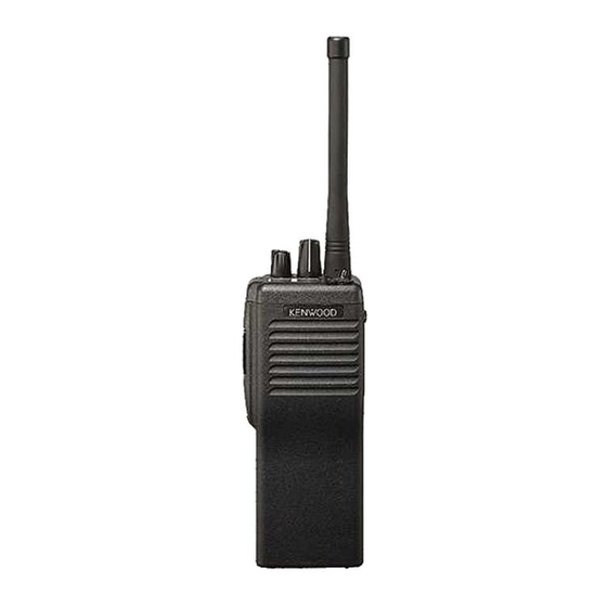
Antenna
(KRA-14 : Option)
Knob assy (SEL)
(K29-5282-04)
Knob assy (VOL)
(K29-5283-04)
Panel assy
(A62-0537-33)
Knob assy
(Side key)
(K29-5216-24)
Cabinet assy
(A02-2139-43)
Photo is TK-290 K type.
Does not come with antenna.
Antenna is available as an option.
© 1998-3 PRINTED IN JAPAN
B51-8423-00 ( N ) 1349
CONTENTS
GENERAL ................................................................. 2
SYSTEM SET-UP ..................................................... 2
OPERATING FEATURES ......................................... 3
REALIGNMENT ...................................................... 10
CIRCUIT DESCRIPTION ......................................... 16
SEMICONDUCTOR DATA ..................................... 23
DESCRIPTION OF COMPONENTS ....................... 26
PARTS LIST ............................................................ 28
EXPLODED VIEW .................................................. 34
PACKING ................................................................ 35
DISASSEMBLY FOR REPAIR ................................ 36
ADJUSTMENT ....................................................... 37
LEVEL DIAGRAM ................................................... 48
CONTROL UNIT (X53-3780-XX) ....................... 49
TX-RX UNIT (X57-5390-10) .............................. 53
SCHEMATIC DIAGRAM ........................................ 59
BLOCK DIAGRAM .................................................. 67
TERMINAL FUNCTION ......................................... 69
KNB-17A (Ni-Cd BATTERY) .................................. 70
KMC-25/26 (SPEAKER MICROPHONE) ............... 71
KSC-19 (CHARGER) ............................................... 72
KSC-20 (RAPID CHARGER) ................................... 72
KPG-36 (PROGRAMMING INTERFACE CABLE) ..... 72
KRA-14 (HELICAL ANTENNA) .............................. 72
SPECIFICATIONS ................................................... 73
CAUTION
When using an external power connector,
please use with maximum final module protec-
tion of 10V
Advertisement
Table of Contents

Related Manuals for Kenwood TK-290


Summary of Contents for Kenwood TK-290
-
Page 1: Table Of Contents
KRA-14 (HELICAL ANTENNA) ......72 SPECIFICATIONS ........... 73 CAUTION When using an external power connector, Photo is TK-290 K type. please use with maximum final module protec- Does not come with antenna. tion of 10V Antenna is available as an option. -
Page 2: General
NOTE quired component for proper identification. WE CANNOT guarantee oscillator stability when using channel element manufactured by other than KENWOOD or its authorized agents. FCC COMPLIANCE AND TYPE NUMBERS Model... -
Page 3: Operating Features
TK-290 OPERATING FEATURES - DTMF keypad (keypad models only) 1. Getting Acquainted Press the keys on the telephone keypad to send DTMF tones. SMA male type Battery pack antenna connector release latch = Universal connector Connect the external speaker/microphone (optional) here. - Page 4 TK-290 OPERATING FEATURES 2) When one priority channel is set : Either priority channel 2. Scan Operating 1 or 2 is scanned. 2-1. Scan Types If a non-priority channel stops temporarily, a priority chan- • Single Group Scan nel signal is detected at certain intervals.
-
Page 5: Optional Features
TK-290 OPERATING FEATURES 2-9. Temporarily Delete/Add 3-4. BCL (Busy Channel Lockout) Override It is possible to delete or add channel temporarily during You can transmit in spite of Busy Channel Lockout situa- scan. When scan stops on unnecessary channel for ex- tion. - Page 6 TK-290 OPERATING FEATURES 3-14. Mode (Enable/Disable) 4. Group Features The transceiver has many special modes mainly for main- You can use these features using the programming soft- tenance. ware (KPG-38D). · Self Programming mode · Panel Test mode 4-1. "TOT" (Time-Out Timer) ·...
-
Page 7: Key Functions
TK-290 OPERATING FEATURES 5. Channel Features 6. Key Functions You can use these features using the programming soft- You can use these features, using the programming soft- ware (KPG-38D). ware (KPG-38D). Selector function is selectable channel se- lect or group select. - Page 8 TK-290 OPERATING FEATURES 6-7. Group Down Toggle PF Keys Speaker/ If this key is pressed once, the group number decreases Function Name Selector Switch Microphone by one step. If this key holds down for 500ms (approxi- PF Keys mate), the group number decreases continuously.
- Page 9 TK-290 OPERATING FEATURES 6-14. Monitor 6-21. Squelch Level Monitor the channel before a transmission. The preset squelch level is varied in user mode (0 to 15). Press this key once, "MON" appears and unmutes Press the key programmed to "squelch level", the trans- speaker if a carrier is present, regardless of the specified ceiver enters to "squelch level adjust mode".
-
Page 10: Realignment
DOS version 3.1 or later on an IBM-PC/XT, AT, or PS2 or Panel tuning mode compatible machine. The data can be input to or read from TK-290 and edited Clear function on the screen. The programmed or edited data can be printed out. - Page 11 TK-290 REALIGNMENT When enter the self programming mode, "FUNC" appears 3. Self Programming after "SEL" is displayed for half a second. Write mode for frequency data and signalling etc. Mainly Selecting any of Channel setting, Group setting, Function used by the person maintaining the user equipment.
- Page 12 TK-290 REALIGNMENT 3-2. Channel Setting Mode • Note Set data for each channel while in this mode. After first 1. Different sample displays are shown. entering Self programming mode, select the "CHAN" display 2. Setting item No.s are displayed with a 7-segment 2-digit with [Top 1] [Top 2] and press [PTT] to set Channel Setting figure on the LCD.
- Page 13 TK-290 REALIGNMENT 3-3. Group Setting Mode 3-4. Function Setting Mode Set data for each Group while in this mode. After first This mode allows making function settings for the trans- entering Self programming mode, select the "GROUP" dis- ceiver. After first entering Self programming mode, select play with [Top 1] [Top 2] and press [PTT] to set Group Set- "FUNC"...
- Page 14 TK-290 REALIGNMENT • Flow Chart 3-5. Clone Mode 1. Connect the cloning interface cable between the master side transceiver (source) and slave side transceiver Self programming mode (clone) as shown in the figure. [Top 1] [Top 2] Function setting mode...
- Page 15 6. Press the master side [PTT] to start cloning. and communications port in the Setup item. 4. Set the firmware to be updated by File select (=F1). 5. Held down the [Side 2] and [PTT]. Turn the TK-290 power [PTT] GRP 1S on, and release [Side 2] first.
-
Page 16: Circuit Description
1. Overview The 1st IF signal is amplified (Q302) and fed into IC300 in The KENWOOD model TK-290 is a VHF/FM hand-held the FM IF IC. The IF signal is then mixed with the 2nd local transceiver designed to operate in the frequency range of oscillator frequency of 45.305MHz to generate the 2nd IF of... - Page 17 TK-290 CIRCUIT DESCRIPTION 3-4. Wide/Narrow changeover circuit 3-5. Audio amplifier circuit • TX-RX unit Narrow and Wide settings can be made for each channel by switching the MCF; XF300 (Wide), XF301 (Narrow) with The demodulated signal from IC300 goes through IC301,...
- Page 18 TK-290 CIRCUIT DESCRIPTION 4-3. Drive and Final amplifier 4. Transmitter System The signal from the T/R switch (D7 is on) is amplified by 4-1. Microphone amplifier the pre-drive (Q6) and drive amplifier (Q8) to 20mW. The The signal from IC3 (control unit) goes through the mute output of the drive amplifier is amplified by the RF power switch (Q403).
- Page 19 1 of the VCXO. The output of the VCXO is applied to pin 8 of the PLL IC. The VCO of TK-290 covers the 38MHz spread, setting 6. Power Supply Circuit frequencies in r1, r2 (receive) and t1, t2 (transmit) with a bias Battery +B is supplied via a 3A fuse from the battery ter- voltage applied to the –V terminal of the VCO.
- Page 20 TK-290 CIRCUIT DESCRIPTION 7-4. D/A converter 7. Control Circuit IC3 and IC603 is used as a conventional semi-fixed-resis- The control unit consists of microprocessor IC406 and its tor converter. It sets the following : peripheral circuits. It controls the TX-RX unit and transfers 1) RX sensitivity data to and from the control unit.
- Page 21 TK-290 CIRCUIT DESCRIPTION 7-6. Low battery warning 8-2. Decode • Low-speed data (QT, DQT) The battery voltage is monitored by the microprocessor (IC406). When the battery voltage falls below the voltage The demodulated signal from the FM IF IC (IC300) is am-...
- Page 22 TK-290 CIRCUIT DESCRIPTION 9-1. Option port 1 (For ANI board etc.) 9. Option Board Terminal Name Function Note Terminals for mounting the option board are provided at DATI Data input Reference the bottom of the TX-RX unit. The table below shows the 1kHz STD Dev →...
-
Page 23: Semiconductor Data
TK-290 SEMICONDUCTOR DATA 1. Microprocessor : MC-8800-802 (TX-RX Unit IC406) 1-1. Terminal function Pin No. Port name Function Pin No. Port name Function A7~A4 NC : Flash memory address bus DTMF clock AD5~AD3 NC : Flash memory address and data bus... - Page 24 TK-290 SEMICONDUCTOR DATA 2. D/A Converter : M62354GP (TX-RX Unit IC3) 2-1. Terminal connection 2-3. Terminal function Pin No. Symbol Function 12-bit shift register MSB bit data is output. When the LD is at the high level, the 12-bit shift register value is loaded to the D/A output register.
- Page 25 TK-290 SEMICONDUCTOR DATA 4. DC-DC Converter : MAX865 (TX-RX Unit IC4) 4-2. Terminal description 4-1. Terminal connection Pin No. Name Function C1– Negative terminal of the flying boost capacitor. 3.3µF Positive terminal of the flying inverting capacitor. C1– C2– Negative terminal of the flying inverting capacitor.
- Page 26 TK-290 SEMICONDUCTOR DATA / DESCRIPTION OF COMPONENTS 7. Active DBM : GN2011 6. VCO System : KCH40 (TX-RX Unit IC10) (TX-RX Unit IC200) 6-1. Circuit diagram 7-1. Circuit diagram –V TX/RX Control Unit (X53-3780-XX) -10 : K -11 : K2 Ref.
-
Page 27: Description Of Components
TK-290 DESCRIPTION OF COMPONENTS TX-RX Unit (X57-5390-10) Ref. No. Use / Function Operation / Condition Ref. No. Use / Function Operation / Condition Level shift Q300 DC switch 1st IF W/N switch sets D/A converter (adjustment) to on when Narrow DC-DC converter Outputs ±... - Page 28 TK-290 ∗ New Parts. indicates safety critical components. L : Scandinavia K : USA P : Canada Parts without Parts No. are not supplied. Y : PX (Far East, Hawaii) T : England E : Europe Les articles non mentionnes dans le Parts No. ne sont pas fournis.
- Page 29 TK-290 CONTROL UNIT (X53-3780-XX) TX-RX UNIT (X57-5390-10) Desti- Desti- Ref. No. Address Parts No. Description Ref. No. Address Parts No. Description parts nation parts nation RK73GB1J470J CHIP R 1/16W C92-0588-05 CHIP-TAN 1.5UF R4,5 RK73GB1J473J CHIP R 1/16W C19,20 CK73GB1C104K CHIP C 0.10UF...
- Page 30 TK-290 TX-RX UNIT (X57-5390-10) Desti- Desti- Ref. No. Address Parts No. Description Ref. No. Address Parts No. Description parts nation parts nation C209,210 CK73GB1H102K CHIP C 1000PF C441 CK73HB1C103K CHIP C 0.010UF C212,213 CK73GB1H102K CHIP C 1000PF C442 CK73FB1C474K CHIP C 0.47UF...
- Page 31 TK-290 TX-RX UNIT (X57-5390-10) Desti- Desti- Ref. No. Address Parts No. Description Ref. No. Address Parts No. Description parts nation parts nation C664 CK73GB1C104K CHIP C 0.10UF CP700-707 R90-0741-05 MULTIPLE RESISTOR C665 CK73GB1C333K CHIP C 0.033UF CP711-716 R90-0741-05 MULTIPLE RESISTOR...
- Page 32 TK-290 TX-RX UNIT (X57-5390-10) Desti- Desti- Ref. No. Address Parts No. Description Ref. No. Address Parts No. Description parts nation parts nation R200 RK73GB1J473J CHIP R 1/16W R421 RK73GB1J223J CHIP R 1/16W R201 RK73GB1J104J CHIP R 100K 1/16W R422 RK73GB1J103J...
- Page 33 TK-290 TX-RX UNIT (X57-5390-10) Desti- Desti- Ref. No. Address Parts No. Description Ref. No. Address Parts No. Description parts nation parts nation ∗ R640 RN73GH1J683D CHIP R 1/16W M62354GP IC (D/A CONVERTER) ∗ R641 RK73GB1J104J CHIP R 100K 1/16W MAX865...
-
Page 34: Exploded View
TK-290 EXPLODED VIEW X53 B/6 X53 F/6 X53 A/6 30x2 X53 C/6 : N14-0577-04 : N14-0578-04 M2.6 x8 BLK : N30-2608-45 M2 x 3 : N78-2030-46 M2 x 4 : N83-2004-46 M2.5 x 4 (Bi-Tap) : N89-2605-46 Parts with the exploded numbers larger than 700 are not supplied. -
Page 35: Packing
TK-290 PACKING 6 Dressing plate (B03-0594-04) 13 Instruction manual 7 Cap (Universal) (B62-0816-00) (B09-0363-03) 16 Stopper (D32-0421-24) 37 Protection bag (H25-0029-04) 62 Screw set (N99-2004-05) 46 Clip (J29-0652-05) 12 Warranty card (B46-0470-00) 36 Packing fixture (H12-3018-02) 38 Item carton case... -
Page 36: Disassembly For Repair
TK-290 DISASSEMBLY FOR REPAIR Disassembly of Front Case and Chassis Remove the Side Key Assy 1. Remove the 2 screws ( ) and a cap fixed screw ( 1. The side key assy is clips form a slide-hook structure. Lift 2. -
Page 37: Adjustment
TK-290 ADJUSTMENT Test Equipment Required for Alignment Test Equipment Major Specifications Standard Signal Generator Frequency Range Maximum 600MHz or more. (SSG) Modulation Frequency modulation and external modulation. Output –133dBm/0.05µV to 7dBm/501mV Power Meter Input Impedance 50Ω. Operation Frequency Up to 600MHz. - Page 38 ADJUSTMENT • Panel tuning Repair Jig (Chassis) Use jig (part No.: A10-1399-03) for repairing the TK-290. Place the TX-RX unit on the jig and fit it with 7 screws. Note : Supply power from an external power supply (Battery terminal : +, jig (chassis) : –)
- Page 39 TK-290 ADJUSTMENT • Clear function Panel Test Mode Pressing [PTT] while holding down [Orange] in Panel test This mode is used for making transceiver connection mode, triggers the clear function which clears all transceiver tests and clearing the memory. data settings.
- Page 40 TK-290 Common Section Measurement Adjustment Item Condition Specifications/Remarks Test- Unit Terminal Unit Parts Method equipment 1. Varicap shift 1) Set panel tuning mode DC VTVM TX-RX TP2 Panel Top1/ –3V ±0.1V voltage Push Side2 to select Top2 ∗ ∗ VSWM...
- Page 41 TK-290 Measurement Adjustment Item Condition Specifications/Remarks Test- Unit Terminal Unit Parts Method equipment 4. TX high 1) Set panel test mode Power meter Panel Check 3.7W~5.2W power CH No. : 1 2.3A or less check Signalling No. : 1 Ammeter PTT : ON 2) CH No.
- Page 42 TK-290 Measurement Adjustment Item Condition Specifications/Remarks Test- Unit Terminal Unit Parts Method equipment 8. Maximum 1) Set panel test mode Power meter Panel Panel Top1/ 3.95kHz ±50Hz deviation CH No. : 3 Deviation Top2 (According to the adjustment Signalling No. : 1 meter larger +, –)
- Page 43 TK-290 Measurement Adjustment Item Condition Specifications/Remarks Test- Unit Terminal Unit Parts Method equipment 11. QT 1) Set panel tuning mode Power meter Panel Panel Top1/ 0.75kHz ±0.05kHz deviation CH No. : 3 Deviation Top2 adjustment Signalling No. : 1 meter...
- Page 44 TK-290 Measurement Adjustment Item Condition Specifications/Remarks Test- Unit Terminal Unit Parts Method equipment 16. DTMF 1) Set panel tuning mode Power meter Panel Panel Top1/ 1.5kHz ±50Hz deviation CH No. : 3 Deviation Top2 adjustment Signalling No. : 1 meter ∗...
- Page 45 TK-290 Measurement Adjustment Item Condition Specifications/Remarks Test- Unit Terminal Unit Parts Method equipment 22. BATT 1) Set panel test mode Power meter Panel Check Cannot transmit detection CH No. : 3 LED (TX) blinks check Signalling No. : 1 DC VTVM Bottom BATT BATT terminal voltage : 5.7V...
- Page 46 TK-290 Measurement Adjustment Item Condition Specifications/Remarks Test- Unit Terminal Unit Parts Method equipment 4. Sensitivity 1) Set panel test mode Panel Panel Top1/ Adjust for maximum 12dB SINAD or more adjustment CH No. : 3 Top2 SINAD and check Signalling No. : 1...
-
Page 47: Level Diagram
TK-290 TK-290 ADJUSTMENT LEVEL DIAGRAM Measurement Adjustment Item Condition Specifications/Remarks Test- Unit Terminal Unit Parts Method equipment 9. Squelch 1) Set panel test mode Panel Panel Top1/ Adjust to point of adjustment CH No. : 3 Top2 opening squelch (narrow) Signalling No. -
Page 48: Pc Board Views
TK-290 TK-290 PC BOARD VIEWS CONTROL UNIT (X53-3780-XX) (A/6) -10 : K -11 : K2 Component side view J72-0523-02 X53-378X-XX (A/6) CONTROL UNIT (X53-3780-XX) (A/6) -10 : K -11 : K2 Foil side view J72-0523-02 X53-378X-XX (A/6) PTTE... - Page 49 TK-290 PC BOARD VIEWS CONTROL UNIT (X53-3780-XX) (B~F/6) -10 : K -11 : K2 Component side view CONTROL UNIT (X53-3780-XX) (B~F/6) -10 : K -11 : K2 Foil side view TOGGLE IC101 R104 LAMP TXLED BLED J72-0523-02 R103 J72-0523-02 X53-378X-XX (B/6)
-
Page 50: Tx-Rx Unit (X57-5390-10)
TK-290 PC BOARD VIEWS TX-RX UNIT (X57-5390-10) Component side view X57-539X-XX Q405 C421 R450 C660 Q402 R411 C430 R677 J72-0519-02 C659 R405 C625 C411 Q401 R402 R669 R400 C416 C623 C435 Q400 R605 R621 C414 R638 C425 R472 C436 C413... - Page 51 TK-290 PC BOARD VIEWS TX-RX UNIT (X57-5390-10) Foil side view X57-539X-XX R315 C311 J72-0519-02 Q302 C330 C331 X300 R318 R317 C304 IC401 C481 R335 R429 C329 C433 R319 C307 C302 C424 C315 C328 L300 C305 IC409 IC407 CF302 CF300 C303...
-
Page 52: Block Diagram
TK-290 TK-290 TK-290 TK-290 BLOCK DIAGRAM... -
Page 53: Terminal Function
TK-290 TK-290 TERMINAL FUNCTION TERMINAL FUNCTION / KNB-17A (Ni-Cd BATTERY) KNB-17A External VIew CN No. Pin No. Name I/O Function CN No. Pin No. Name I/O Function CN No. Pin No. Name I/O Function BTL input + for external speaker. -
Page 54: Kmc-25/26 (Speaker Microphone)
TK-290 KMC-25/26 (SPEAKER MICROPHONE) KMC-25 External View KMC-25/26 Circuit Diagram Universal SP/MIC connector EXT. ANT (KMC-26) SP– If the earphone jack output is too high, adjust the value of resistor R12. Earphone R12 0 jack ø3.5 2.2K 10µ Shield –... -
Page 55: Charger)
TK-290 KSC-19 (CHARGER) / KSC-20 (RAPID CHARGER) / KPG-36 (PRO- GRAMMING INTERFACE CABLE) / KRA-14 (HELICAL ANTENNA) KSC-19 External View KPG-36 External View KSC-19 Charging KNB-17A Voltage ..........7.2V Battery capacity ........1500mAh Charging time ........Approx. 8 hours KSC-20 External View... -
Page 56: Specifications
TK-290 SPECIFICATIONS GENERAL Frequency Range ..........136 to 174MHz Number of Channels ..........160 channels Channel Spacing ..........Wide : 25kHz, 30kHz, Narrow : 12.5kHz, 25kHz (PLL channel step 5kHz, 6.25kHz, 7.5kHz) Battery Voltage ............ 7.5V DC ± 20% Battery Life ............10 hours at 5W (5-5-90 duty cycle) Temperature Range .......... - Page 57 Mechelsesteenweg 418 B-1930 Zaventem, Belgium KENWOOD ELECTRONICS FRANCE S.A. 13, Boulevard Ney, 75018 Paris, France KENWOOD ELECTRONICS U.K. LIMITED KENWOOD House, Dwight Road, Watford, Herts., WD1 8EB United Kingdom KENWOOD ELECTRONICS EUROPE B.V. Amsterdamseweg 37, 1422 AC Uithoorn, The Netherlands KENWOOD ELECTRONICS ITALIA S.p.A.