Table of Contents
Advertisement
Y9520Z Sundial RF ² Pack 5
INSTALLATION INSTRUCTIONS
Application
This pack provides a wireless control solution for adding 2 wireless room
thermostats to heating systems, in order to split the heating system
into 2 separate zones and ensure compliance with the latest Building
Regulations.
Pack Contents & Product Descriptions
1 x ST9520C1005
Wireless enabled 7 day programmer with 2
output control relays for switching boilers, pumps
and zone valves in heating systems. It requires
permanent mains 230Vac power.
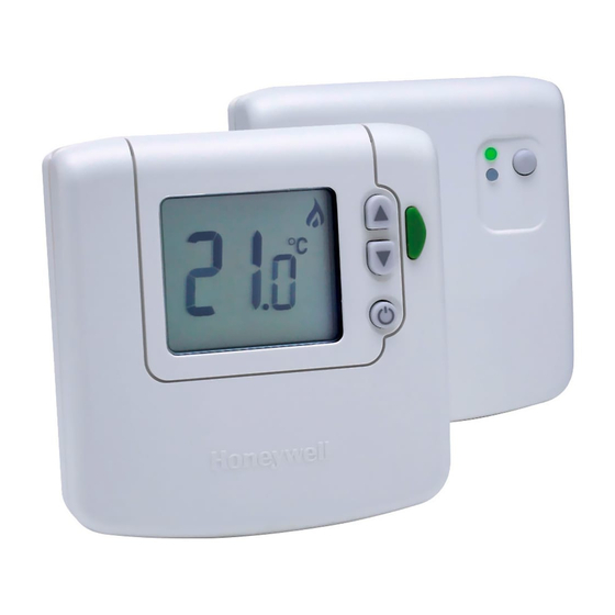
2 x DTS92E1020
Wireless digital room thermostat with energy
saving ECO function. It operates on 2 x AA alkaline
batteries, giving a battery life of at least 2 years
under typical operating conditions.
2 x table stand for DT92E (optional)
Other Honeywell products, not supplied in this pack, may be required
for a complete installation, depending on the application. For example
BDR91T1004 relay box. See Schematic System Layouts (below) or refer
to www.honeywelluk.com for full details.
This document is to be left with the user
Schematic System Layouts
95-1 Wireless room thermostats, wired valves, wired TPI
boiler control
ST9520C
Hot Water
Junction
Box
95-3 Wireless room thermostats, wired valves, wireless
TPI boiler control
BDR91T
ST9520C
Hot Water
Junction
Boiler
Box
ZONE 1
DT92E
V4043H
Radiator(s)
ZONE 2
DT92E
V4043H
Radiator(s)
ZONE 1
DT92E
V4043H
Radiator(s)
ZONE 2
DT92E
V4043H
Radiator(s)
Honeywell
Sundial RF ² is a registered
2-way wireless
trademark of Honeywell Inc.
communication
System Operation
DT92E and ST9520C use 2-way communication on an 868MHz radio
frequency (RF) band to control the heating system.
ST9520C operates as the control hub of the system and the DT92E
thermostats are free to be positioned in suitable locations in the 2
separate heating zones.
This functionality is ideal for upgrading existing systems without a room
thermostat to ensure compliance with Building Regulations. It is also ideal
for refurbished systems, where running mains cable from the programmer
to the thermostats and back to the boiler is difficult or impractical.
There are various options for how to connect to the boiler. The simplest
is a direct 230Vac connection. If the boiler supports OpenTherm
communications technology, it is possible to control it using a 2-wire
connection from the ST9520C OpenTherm terminals. If the boiler is
located remotely, it is possible to send the switching signal from the
ST9520C to a remote located BDR91T relay box.
95-2 Wireless room thermostats, wired valves, OpenTherm 2
wire boiler control
ST9520C
OpenTherm®
Hot Water
2-wire connection
Junction
Boiler
Box
1
OpenTherm®
communication
ZONE 1
DT92E
V4043H
Radiator(s)
ZONE 2
DT92E
V4043H
Radiator(s)
Advertisement
Table of Contents

Related Manuals for Honeywell Y9520Z Sundial RF2 Pack 5


Summary of Contents for Honeywell Y9520Z Sundial RF2 Pack 5
-
Page 1: Installation Instructions
Building Regulations. It is also ideal for refurbished systems, where running mains cable from the programmer Other Honeywell products, not supplied in this pack, may be required to the thermostats and back to the boiler is difficult or impractical. -
Page 2: Table Of Contents
The RF link between the Room Thermostats (DT92E) and the Zone Section Page Programmer (ST9520C) in Honeywell system packs is pre-configured 1 INSTALLING THE ST9520C PROGRAMMER at the factory and therefore all units should be installed at the same site. -
Page 3: Installing The St9520C Programmer
INSTALLING THE ST9520C PROGRAMMER 1.1 Mounting ST9520C For best performance, install in an open space. Leave at least 30cm To remove the unit from the wall-plate, distance from any metal objects including pipes and the boiler housing. slacken the two securing screws at the bottom of ST9520C and hinge the unit After locating the DT92E room thermostats, use the Signal Strength up to separate the two halves. -
Page 4: St9520C Internal Wiring
1.5 ST9520C Internal Wiring Notes DT92E is completely wireless and so is not shown connected on Clock these wiring diagrams. The ST9520C is a Class II (double insulated) device. A parking terminal is provided for earth wiring continuity, if required. N L 1 2 3 4 230V~ 50...60Hz... -
Page 5: Replacing Other Time Controls
ST9520C may mount on the back-plate of existing time controls, but it is likely major wiring changes will be required for compatibility with the plumbing and controls changes. Refer to the Honeywell Technical Help Desk for advice. 1.8 Powering Up ST9520C Check the unit powers up correctly and that the display does not remain blank. -
Page 6: Installing The Dt92E Room Thermostat
Now go to section 2.3 to conduct the Signal Strength Test. Zone ID Number (1 or 2) 2.3 DT92E Signal Strength Test Honeywell 2-way RF communications allows signal strength testing to ensure DT92E can be positioned in the best possible location. To enter Signal Strength Test:... -
Page 7: Mounting Dt92E
2.4 Mounting DT92E DT92E can be mounted (a) directly on a wall, or (b) on the optional table stand provided. Wall mounting is recommended as it ensures a position of high signal strength can be maintained. For wall mounting, install the mounting plate first, then follow If the optional table stand is to be used, first assemble the two steps 1, 2 and 3 to hinge the front piece on, as shown in the pieces together as shown. -
Page 8: Installing The Bdr91T Wireless Relay Box
INSTALLING THE BDR91T WIRELESS RELAY BOX (IF REQUIRED) If the heating boiler is located remotely it is possible to control it using a wireless relay box BDR91T1000. This is not supplied in this pack and must be purchased separately. After installation it must be bound (paired) to the ST9520C timer and then the signal strength should be verified to ensure the location chosen is suitable. -
Page 9: System Configuration: St9520C
SYSTEM CONFIGURATION: ST9520C 4.1 ST9520C Installer Modes ST9520C has 4 Installer Modes that enable the product to be customized for the application and for the needs of the User. Each adjustable feature is called a Parameter, and is represented by a number or letter ID and a value. The Modes are:- •... -
Page 10: Installer Setup
4.3 Installer Setup The system can be set up to operate in a variety of different ways to suit the application, or the user lifestyle or preferences. This setup is done via the ST9520C Installer Setup. The features that can be adjusted are called Installer Parameters, and are listed in the table below, along with a description of the options that are possible. -
Page 11: Installer Setup Flowchart
Note: When OpenTherm is enabled, BOILER binding is not possible and anything already bound in the BOILER binding slot is deleted (see page 16). Refer to Honeywell Technical Help Desk for wireless OpenTherm possibilities using the R8810A OpenTherm receiver. -
Page 12: Set Service
4.5 OpenTherm® Setup and Information Display (cont.) To Enter Set OpenTherm Mode: Enter Installer Modes (as described on page 9) and navigate to SET OPENTHERM mode. In response to the query ‘SET OPENTHERM OK ?’, press the button to enter SET OPENTHERM. The first OpenTherm parameter ‘Ot’... - Page 13 4.6 Set Service (cont.) To Enter Set Service Mode: Enter Installer Modes (as described on Page 9) and navigate to SET SERVICE mode. In response to the query ‘SET SERVICE OK ?’ press the button to enter SET SERVICE. The message ‘ENTER PIN’ will now be displayed, along with the 4-digit entry code format 0---.
-
Page 14: Change Pin
4.7 Change PIN If you intend to change the PIN code, please ensure you take a note of the new code that you are setting. The process for changing the current PIN code is as follows: Enter Installer Modes (as described on Page 9) and navigate to CHANGE PIN mode. In response to the query ‘CHANGE PIN OK ?’ press the button to enter CHANGE PIN mode. -
Page 15: System Configuration: Dt92E
SYSTEM CONFIGURATION: DT92E 5.1 DT92E Installer Mode Like ST9520C, DT92E also has an Installer Mode to enable it to be Parameter Value customized for the application. Each adjustable feature is called a Parameter, and is represented by a letter ID and a value on the display, as shown. -
Page 16: Binding / Re-Binding Procedure
BINDING / RE-BINDING PROCEDURE 6.1 Binding 2-way RF devices that communicate with each other achieve this through having each others unique addresses written in their memories. This allows each device to know which other device to communicate with. The process of writing these addresses is known as Binding. All devices in the pack are pre-bound at the factory. -
Page 17: Binding Menu Display
6.4 Binding Menu Display SENSOR : means temperature sensor BOILER : means output device wired to boiler CONTROL : means output device wired to zone valve Zone 2 Zone 1 Boiler bnd : indicates something is already bound in this slot -- -- : indicates nothing is currently bound in this slot 6.5 How to Bind DT92E to ST9520C... -
Page 18: How To Bind Bdr91T To St9520C
• It is only possible to bind a BDR91T if both sensors (DT92E) have already been bound to the sensor slots in ST9520C. • BDR91T can be bound as a CONTROL device, to operate a zone valve for example (refer to Honeywell for supported applications) or as a BOILER control (refer to Binding Table in section 6.2 for details). Ensure the ST9520C slider is in the RUN position, then press and hold and Zone 2 MODE buttons for 8 seconds to access the Guided Binding Menu. -
Page 19: How To Test Bdr91T Signal Strength
6.7 How to Test BDR91T Signal Strength Honeywell 2-way RF communications allows signal strength testing to verify BDR91T is positioned in the best possible location. Enter ST9520C Guided Binding Menu (ensure the slider is in the RUN position, then press and hold and Zone 2 MODE buttons for 8 seconds. -
Page 20: Commissioning The System
Honeywell for guidance. Honeywell cannot be held responsible for misapplication of the product(s) described within this document. Manufactured for and on behalf of the Environmental and Combustion Controls Division of Honeywell Technologies Sàrl, ACS-ECC EMEA, Z.A. La Pièce 16, 1180 Rolle, Switzerland, by its Authorised Representative Honeywell Inc.