Draytek Vigor2920n User Manual
Dual-wan security router
Hide thumbs
Also See for Vigor2920n:
- User manual (434 pages) ,
- User manual (317 pages) ,
- User manual (40 pages)
Table of Contents
Advertisement
Quick Links
Advertisement
Table of Contents

Related Manuals for Draytek Vigor2920n


Summary of Contents for Draytek Vigor2920n
- Page 2 Vigor2920 Series User’s Guide...
- Page 3 Vigor2920 Series Dual-WAN Security Router User’s Guide Version: 1.1 Firmware Version: V3.3.6 Date: 07/12/2010 Vigor2920 Series User’s Guide...
-
Page 4: Copyright Information
Web registration is preferred. You can register your Vigor router via Owner http://www.DrayTek.com. Firmware & Tools Due to the continuous evolution of DrayTek technology, all routers will be regularly Updates upgraded. Please consult the DrayTek web site for more information on newest firmware, tools and documents. -
Page 5: European Community Declarations
Product: Vigor2920 Series Router DrayTek Corp. declares that Vigor2920 Series of routers are in compliance with the following essential requirements and other relevant provisions of R&TTE Directive 1999/5/EEC. The product conforms to the requirements of Electro-Magnetic Compatibility (EMC) Directive 2004/108/EC by complying with the requirements set forth in EN55022/Class B and EN55024/Class B. - Page 6 Vigor2920 Series User’s Guide...
-
Page 7: Table Of Contents
Preface .......................1 1.1 Web Configuration Buttons Explanation ................. 1 1.2 LED Indicators and Connectors ....................2 1.2.1 For Vigor2920 ........................2 1.2.2 For Vigor2920n ......................... 4 1.2.3 For Vigor2920Vn....................... 6 1.3 Hardware Installation ......................8 1.4 Printer Installation ........................9 Configuring Basic Settings ................15... - Page 8 3.4 Applications ........................... 59 3.4.1 Dynamic DNS ......................... 59 3.4.2 UPnP..........................62 3.5 VoIP............................63 3.5.1 DialPlan .......................... 65 3.5.2 SIP Accounts ........................74 3.5.3 Phone Settings ....................... 78 3.5.4 Status..........................83 3.6 Wireless LAN ........................84 3.6.1 Basic Concepts....................... 84 3.6.2 General Setup.........................
- Page 9 4.3.3 Open Ports........................139 4.4 Firewall ..........................142 4.4.1 Basics for Firewall......................142 4.4.2 General Setup....................... 144 4.4.3 Filter Setup ........................147 4.4.4 DoS Defense ........................ 156 4.5 User Management....................... 159 4.5.1 General Setup....................... 160 4.5.2 User Profile ........................161 4.5.3 User Group ........................
- Page 10 4.12.3 Phone Settings ......................251 4.12.4 Status.......................... 257 4.13 Wireless LAN ........................258 4.13.1 Basic Concepts......................258 4.13.2 General Setup......................260 4.13.3 Security ........................263 4.13.4 Access Control......................265 4.13.5 WPS..........................267 4.13.6 WDS..........................269 4.13.7 Advanced Setting......................272 4.13.8 WMM Configuration ....................273 4.13.9 AP Discovery ......................
- Page 11 5.8 Creating an Account for MyVigor ..................328 5.8.1 Creating an Account via Vigor Router ................328 5.8.2 Creating an Account via MyVigor Web Site..............332 Trouble Shooting ..................337 6.1 Checking If the Hardware Status Is OK or Not..............337 6.2 Checking If the Network Connection Settings on Your Computer Is OK or Not ....
-
Page 13: Preface
Vigor2920 series is a broadband router. It integrates IP layer QoS, NAT session/bandwidth management to help users control works well with large bandwidth. By adopting hardware-based VPN platform and hardware encryption of AES/DES/3DS, the router increases the performance of VPN greatly, and offers several protocols (such as IPSec/PPTP/L2TP) with up to 2 VPN tunnels. -
Page 14: Led Indicators And Connectors
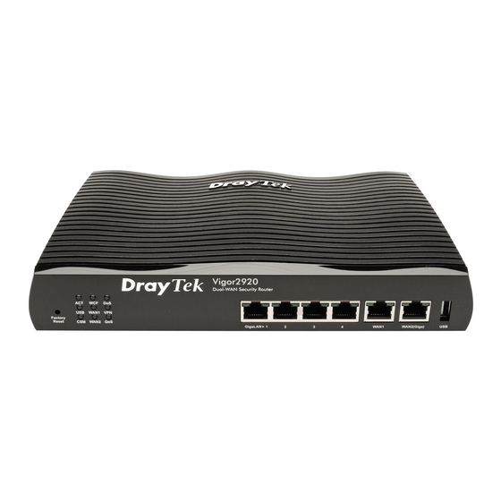
Before you use the Vigor router, please get acquainted with the LED indicators and connectors first. Status Explanation ACT (Activity) Blinking The router is powered on and running normally. The router is powered off. USB device is connected and ready for use. Blinking The data is transmitting. - Page 15 Interface Description Factory Reset Restore the default settings. Usage: Turn on the router (ACT LED is blinking). Press the hole and keep for more than 5 seconds. When you see the ACT LED begins to blink rapidly than usual, release the button. Then the router will restart with the factory default configuration.
-
Page 16: For Vigor2920N
Status Explanation ACT (Activity) Blinking The router is powered on and running normally. The router is powered off. USB device is connected and ready for use. Blinking The data is transmitting. The profile(s) of CSM (Content Security Management) for IM/P2P, URL/Web Content Filter application is enabled from Firewall >>General Setup. - Page 17 Interface Description Wireless LAN Press "Wireless LAN ON/OFF/WPS" button once to wait for client device ON/OFF/WPS making network connection through WPS. Press "Wireless LAN ON/OFF/WPS" button twice to enable (WLAN LED on) or disable (WLAN LED off) wireless connection. Factory Reset Restore the default settings.
-
Page 18: For Vigor2920Vn
Status Explanation ACT (Activity) Blinking The router is powered on and running normally. The router is powered off. USB device is connected and ready for use. Blinking The data is transmitting. The profile(s) of CSM (Content Security Management) for IM/P2P, URL/Web Content Filter application can be enabled from Firewall >>General Setup. - Page 19 Interface Description Wireless LAN Press "Wireless LAN ON/OFF/WPS" button once to wait for client device ON/OFF/WPS making network connection through WPS. Press "Wireless LAN ON/OFF/WPS" button twice to enable (WLAN LED on) or disable (WLAN LED off) wireless connection. Factory Reset Restore the default settings.
-
Page 20: Hardware Installation
Before starting to configure the router, you have to connect your devices correctly. Connect the cable Modem/DSL Modem/Media Converter to any WAN port of router with Ethernet cable (RJ-45). Connect one end of an Ethernet cable (RJ-45) to one of the LAN ports of the router and the other end of the cable (RJ-45) into the Ethernet port on your computer. -
Page 21: Printer Installation
You can install a printer onto the router for sharing printing. All the PCs connected this router can print documents via the router. The example provided here is made based on Windows XP/2000. For Windows 98/SE/Vista, please visit www.DrayTek.com. Before using it, please follow the steps below to configure settings for connected computers (or wireless clients). - Page 22 Click Local printer attached to this computer and click Next. In this dialog, choose Create a new port Type of port and use the drop down list to select Standard TCP/IP Port. Click Next. Vigor2920 Series User’s Guide...
- Page 23 In the following dialog, type 192.168.1.1 (router’s LAN IP) in the field of Printer Name or IP Address and type IP_192.168.1.1 as the port name. Then, click Next. Click Standard and choose Generic Network Card. Then, in the following dialog, click Finish. Vigor2920 Series User’s Guide...
- Page 24 Now, your system will ask you to choose right name of the printer that you installed onto the router. Such step can make correct driver loaded onto your PC. When you finish the selection, click Next. 10. For the final stage, you need to go back to Control Panel-> Printers and edit the property of the new printer you have added.
- Page 25 If you do not know whether your printer is supported or not, please visit www.DrayTek.com to find out the printer list. Open Support >FAQ; find out the link of Printer Server and click it; then click the What types of printers are compatible with Vigor router? link.
- Page 26 This page is left blank. Vigor2920 Series User’s Guide...
-
Page 27: Configuring Basic Settings
For using the router properly, it is necessary for you to change the password of web configuration for security and adjust primary basic settings. This chapter explains how to setup a password for an administrator/user and how to adjust basic/advanced settings for accessing Internet successfully. For user mode operation, do not type any word on the window and click Login for the simple web pages for configuration. -
Page 28: Changing Password
The web page can be logged out according to the chosen condition. The default setting is Auto Logout, which means the web configuration system will logout after 5 minutes without any operation. Change the setting for your necessity. No matter user mode operation or admin mode operation, please change the password for the original security of the router. - Page 29 Main screen for user mode operation (simple configuration) Note: The home page will change slightly in accordance with the type of the router you have. Go to System Maintenance page and choose Administrator Password/User Password. Enter the login password (the default is blank) on the field of Old Password. Type New Password.
-
Page 30: Quick Start Wizard
Notice: Quick Start Wizard for user mode operation is the same as for admin mode operation. If your router can be under an environment with high speed NAT, the configuration provide here can help you to deploy and use the router quickly. The first screen of Quick Start Wizard is entering login password. -
Page 31: For Wan1/Wan2
On the next page as shown below, please select the WAN interface that you use. If Ethernet interface is used, please choose WAN1/2 (based on the physical hardware connection); if 3G USB modem is used, please choose WAN3. Choose Auto negotiation as the physical type for your router. - Page 32 PPPoE stands for Point-to-Point Protocol over Ethernet. It relies on two widely accepted standards: PPP and Ethernet. It connects users through an Ethernet to the Internet with a common broadband medium, such as wireless device or cable modem. All the users over the Ethernet can share a common connection.
- Page 33 Click Finish. A page of Quick Start Wizard Setup OK!!! will appear. Then, the system status of this protocol will be shown. Click PPTP/L2TP as the protocol. Type in all the information that your ISP provides for this protocol. Click Next for viewing summary of such connection. Vigor2920 Series User’s Guide...
- Page 34 Click Finish. A page of Quick Start Wizard Setup OK!!! will appear. Then, the system status of this protocol will be shown. Click Static IP as the protocol. Type in all the information that your ISP provides for this protocol. After finishing the settings in this page, click Next to see the following page.
- Page 35 Click Finish. A page of Quick Start Wizard Setup OK!!! will appear. Then, the system status of this protocol will be shown. Click DHCP as the protocol. Type in all the information that your ISP provides for this protocol. After finishing the settings in this page, click Next to see the following page. Vigor2920 Series User’s Guide...
-
Page 36: For Wan3
Click Finish. A page of Quick Start Wizard Setup OK!!! will appear. Then, the system status of this protocol will be shown. To use 3G USB modem for network connection, please choose WAN3. Then, click Next to continue. Click Finish. A page of Quick Start Wizard Setup OK!!! will appear. Then, the system status of this protocol will be shown. -
Page 37: Service Activation Wizard
Service Activation Wizard is a tool which allows you to use trial version or update the license of WCF directly without accessing into the server (MyVigor) located on http://myvigor.draytek.com. For using Web Content Filter Profile, please refer to later section Web Content Filter Profile for detailed information. - Page 38 When you finish the selection, please click Next. Commtouch is the web content filter based on Commtouch operated in the worldwide. There is a 30-day trial period. After trial, you can purchase DrayTek's prepared Commtouch GlobalView WCF package from retailing outlets.
- Page 39 Note: The service will be activated and applied as the default rule configured in Firewall>>General Setup. Now, the web page will display the service that you have activated according to your selection(s). The valid time for the free trial of these services is 30-day. Later, if you need to extend the license valid time for the same service, you can also use the Service Activation Wizard again to reach your goal by clicking the radio button of Formal edition with license key and clicking Next.
-
Page 40: Online Status
Such page displays the physical connection status such as LAN connection status, WAN connection status, ADSL information, and so on. If you select PPPoE as the protocol, you will find out a link of Dial PPPoE or Drop PPPoE in the Online Status web page. Detailed explanation is shown below: LAN Status Primary DNS... -
Page 41: Virtual Wan
Displays the IP address of the WAN interface. GW IP Displays the IP address of the default gateway. TX Packets Displays the total transmitted packets at the WAN interface. TX Rate Displays the speed of transmitted octets at the WAN interface. RX Packets Displays the total number of received packets at the WAN interface. -
Page 42: Support Area
When you click the menu item under Support Area, you will be guided to visit www.draytek.com and open the corresponding pages directly. Click Support Area>>Product Registration, the following web page will be displayed. Vigor2920 Series User’s Guide... -
Page 43: User Mode Operation
This chapter will guide users to execute simple configuration through user mode operation. As for other examples of application, please refer to chapter 5. Open a web browser on your PC and type http://192.168.1.1. The window will ask for typing username and password. Do not type any word (both username and password are Null for user operation) on the window and click Login on the window. - Page 44 USB port of Vigor2920, it can support HSDPA/UMTS/EDGE/GPRS/GSM and the future 3G standard (HSUPA, etc). Vigor2920n/Vn with 3G USB Modem allows you to receive 3G signals at any place such as your car or certain location holding outdoor activity and share the bandwidth for using by more people.
-
Page 45: General Setup
Therefore, when WAN1/WAN2 is not available, the router will use 3.5G for supporting automatically. The supported 3G USB Modem will be listed on Draytek web site. Please visit www.draytek.com for more detailed information. Below shows the menu items for WAN. - Page 46 interface. Active Mode Display whether such WAN interface is used as Active device or backup device. Display the Backup WAN interface for such WAN when it is Backup WAN disabled. Note: In default, each WAN port is enabled. Be aware that WAN2 is fixed with physical mode of Giga Ethernet. Enable Choose Yes to invoke the settings for this WAN interface.
- Page 47 WAN while sending them out. Please type the tag value and specify the priority for the packets sending by WAN1. Disable – Disable the function of VLAN with tag. Tag value – Type the value as the VLAN ID number. The range is form 0 to 4095.
- Page 48 To use 3G network connection through 3G USB Modem, please configure WAN3 interface. Choose Yes to invoke the settings for this WAN interface. Enable Choose No to disable the settings for this WAN interface. Display Name Type the description for such WAN interface. Physical Mode Display the physical mode of such WAN interface.
- Page 49 the WAN interface should play if you want to backup multiple WANs. However, ignore this setting if you want to backup a single WAN. When any WAN disconnect – Such backup WAN will be activated when any master WAN interface disconnects. When all WAN disconnect –...
-
Page 50: Internet Access
For the router supports multi-WAN function, the users can set different WAN settings (for WAN1/WAN2/WAN3) for Internet Access. Due to different Physical Mode for WAN interfaces, the Access Mode for these connections also varies. Refer to the following figures. Index Display the WAN interface. - Page 51 Enable/Disable Click Enable for activating this function. If you click Disable, this function will be closed and all the settings that you adjusted in this page will be invalid. ISP Access Setup Enter your allocated username, password and authentication parameters according to the information provided by your ISP. Username –...
- Page 52 WAN IP Alias - If you have multiple public IP addresses and would like to utilize them on the WAN interface, please use WAN IP Alias. You can set up to 8 public IP addresses other than the current one you are using. Fixed IP –...
- Page 53 Static or Dynamic IP Click Enable for activating this function. If you click Disable, this function will be closed and all the settings that you adjusted in this page will be invalid. Keep WAN Connection Normally, this function is designed for Dynamic IP environments because some ISPs will drop connections if there is no traffic within certain periods of time.
- Page 54 Settings and allows you type in IP address manually. WAN IP Alias - If you have multiple public IP addresses and would like to utilize them on the WAN interface, please use WAN IP Alias. You can set up to 8 public IP addresses other than the current one you are using.
- Page 55 To use PPTP/L2TP as the accessing protocol of the internet, please choose PPTP/L2TP from Internet Access menu. The following web page will be shown. PPTP/L2TP Client Mode Enable PPTP- Click this radio button to enable a PPTP client to establish a tunnel to a DSL modem on the WAN interface. Enable L2TP - Click this radio button to enable a L2TP client to establish a tunnel to a DSL modem on the WAN interface.
- Page 56 WAN IP Alias - If you have multiple public IP addresses and would like to utilize them on the WAN interface, please use WAN IP Alias. You can set up to 8 public IP addresses other than the current one you are using. Fixed IP - Usually ISP dynamically assigns IP address to you each time you connect to it and request.
- Page 57 Enable / Disable Click Enable for activating this function. If you click Disable, this function will be closed and all the settings that you adjusted in this page will be invalid. SIM PIN code Type PIN code of the SIM card that will be used to access Internet.
-
Page 58: Load-Balance Policy
After finishing all the settings here, please click OK to activate them. This router supports the function of load balancing. It can assign traffic with protocol type, IP address for specific host, a subnet of hosts, and port range to be allocated in WAN interface. The user can assign traffic category and force it to go to dedicate network interface based on the following web page setup. - Page 59 Click Index 1 to access into the following page for configuring load-balance policy. Enable Check this box to enable this policy. Use the drop-down menu to choose a proper protocol for the Protocol WAN interface. Choose the WAN interface (WAN1 / WAN2 / WAN3) for Binding WAN interface binding.
-
Page 60: Lan
Local Area Network (LAN) is a group of subnets regulated and ruled by router. The design of network structure is related to what type of public IP addresses coming from your ISP. The most generic function of Vigor router is NAT. It creates a private subnet of your own. As mentioned previously, the router will talk to other public hosts on the Internet by using public IP address and talking to local hosts by using its private IP address. -
Page 61: General Setup
Vigor router will exchange routing information with neighboring routers using the RIP to accomplish IP routing. This allows users to change the information of the router such as IP address and the routers will automatically inform for each other. This page provides you the general settings for LAN. Click LAN to open the LAN settings page and choose General Setup. - Page 62 Disable. IP Address Type in secondary IP address for connecting to a subnet. (Default: 192.168.2.1/ 24) An address code that determines the size of the network. (Default: Subnet Mask 255.255.255.0/ 24) DHCP Server You can configure the router to serve as a DHCP server for the 2nd subnet.
- Page 63 the 1st subnet with neighboring routers. 2nd Subnet - Select the router to change the RIP information of the 2nd subnet with neighboring routers. DHCP stands for Dynamic Host Configuration Protocol. The DHCP Server router by factory default acts a DHCP server for your network so Configuration it automatically dispatch related IP settings to any local user configured as a DHCP client.
-
Page 64: Nat
one DNS Server. If your ISP does not provide it, the router will automatically apply default secondary DNS Server IP address: 194.98.0.1 to this field. The default DNS Server IP address can be found via Online Status: If both the Primary IP and Secondary IP Address fields are left empty, the router will assign its own IP address to local users as a DNS proxy server and maintain a DNS cache. -
Page 65: Port Redirection
Port Redirection is usually set up for server related service inside the local network (LAN), such as web servers, FTP servers, E-mail servers etc. Most of the case, you need a public IP address for each server and this public IP address/domain name are recognized by all users. Since the server is actually located inside the LAN, the network well protected by NAT of the router, and identified by its private IP address/port, the goal of Port Redirection function is to forward all access request with public IP address from external users to the mapping private IP... - Page 66 Enable Check this box to enable such port redirection setting. Mode Two options (Single and Range) are provided here for you to choose. To set a range for the specific service, select Range. In Range mode, if the public port (start port and end port) and the starting IP of private IP had been entered, the system will calculate and display the ending IP of private IP automatically.
-
Page 67: Dmz Host
As mentioned above, Port Redirection can redirect incoming TCP/UDP or other traffic on particular ports to the specific private IP address/port of host in the LAN. However, other IP protocols, for example Protocols 50 (ESP) and 51 (AH), do not travel on a fixed port. Vigor router provides a facility DMZ Host that maps ALL unsolicited data on any protocol to a single host in the LAN. - Page 68 DMZ Host for WAN2 and WAN3 is slightly different with WAN1. See the following figure. If you previously have set up WAN Alias for PPPoE or Static or Dynamic IP mode, you will find them in Aux. WAN IP for your selection. Enable Check to enable the DMZ Host function.
-
Page 69: Open Ports
Open Ports allows you to open a range of ports for the traffic of special applications. Common application of Open Ports includes P2P application (e.g., BT, KaZaA, Gnutella, WinMX, eMule and others), Internet Camera etc. Ensure that you keep the application involved up-to-date to avoid falling victim to any security exploits. - Page 70 Enable Open Ports Check to enable this entry. Comment Make a name for the defined network application/service. WAN Interface Specify the WAN interface that will be used for this entry. Local Computer Enter the private IP address of the local host or click Choose PC to select one.
-
Page 71: Applications
Below shows the menu items for Applications. The ISP often provides you with a dynamic IP address when you connect to the Internet via your ISP. It means that the public IP address assigned to your router changes each time you access the Internet. - Page 72 Domain Name Display the domain name that you set on the setting page of DDNS setup. Active Display if this account is active or inactive. Display DDNS log status. View Log Force Update Force the router updates its information to DDNS server. Select Index number 1 to add an account for the router.
- Page 73 Use the drop down list to choose the desired domain. Login Name Type in the login name that you set for applying domain. Password Type in the password that you set for applying domain. Wildcard and Backup The Wildcard and Backup MX features are not supported for all Dynamic DNS providers.
-
Page 74: Upnp
The UPnP (Universal Plug and Play) protocol is supported to bring to network connected devices the ease of installation and configuration which is already available for directly connected PC peripherals with the existing Windows 'Plug and Play' system. For NAT routers, the major feature of UPnP on the router is “NAT Traversal”. -
Page 75: Voip
The reminder as regards concern about Firewall and UPnP Can't work with Firewall Software Enabling firewall applications on your PC may cause the UPnP function not working properly. This is because these applications will block the accessing ability of some network ports. - Page 76 very similar to a URL so some may call it “SIP URL”. SIP supports peer-to-peer direct calling and also calling via a SIP proxy server (a role similar to the gatekeeper in H.323 networks), while the MGCP protocol uses client-server architecture, the calling scenario being very similar to the current PSTN/ISDN network.
-
Page 77: Dialplan
available bandwidth, but Vigor V models also equip with automatic QoS assurance. QoS Assurance assists to assign high priority to voice traffic via Internet. You will always have the required inbound and outbound bandwidth that is prioritized exclusively for Voice traffic over Internet but you just get your data a little slower and it is tolerable for data traffic. - Page 78 2. Even no voice prompt, but the RTP traffic is still secured until the call ends. Note: If the incoming or outgoing calls do not match any entry on the phonebook, the router will try to make the call "being protected". But, if the call ends up "unprotected"(e.g. peer side does not support ZRTP+SRTP), the router will not play out a warning message.
- Page 79 SIP URL Enter your friend’s SIP Address. Dial Out Account Choose one of the SIP accounts for this profile to dial out. It is useful for both sides (caller and callee) that registered to different SIP Registrar servers. If caller and callee do not use the same SIP server, sometimes, the VoIP phone call connection may not succeed.
- Page 80 For the convenience of user, this page allows users to edit prefix number for the SIP account with adding number, stripping number or replacing number. It is used to help user having a quick and easy way to dial out through VoIP interface. Enable Check this box to invoke this setting.
- Page 81 OP Number The front number you type here is the first part of the account number that you want to execute special function (according to the chosen mode) by using the prefix number. Min Len Set the minimal length of the dial number for applying the prefix number settings.
- Page 82 Enable Click this to enable this entry. Call Direction Determine the direction for the phone call, IN – incoming call, OUT-outgoing call, IN & OUT – both incoming and outgoing calls. Barring Type Determine the type of the VoIP phone call, URI/URL or number.
- Page 83 For Block IP Address – this function can block incoming calls (through Phone port) coming from IP address. Such control also can be done based on preconfigured schedules. This page allows you to process incoming or outgoing phone calls by regional. Default values (common used in most areas) will be shown on this web page.
- Page 84 Call Forward [All][Act] Dial the number typed in this field to forward all the incoming calls to the specified place. Call Forward [Deact] Dial the number typed in this field to release the call forward function. Call Forward [Busy][Act] Dial the number typed in this field to forward all the incoming calls to the specified place while the phone is busy.
- Page 85 Some emergency phone (e.g., 911) or special phone cannot be dialed out by using VoIP and can be called out through PSTN line only. To solve this problem, this page allows you to set five sets of PSTN number for dialing without passing through Internet. Please type the number in the field of phone number for PSTN relay.
-
Page 86: Sip Accounts
In this section, you set up your own SIP settings. When you apply for an account, your SIP service provider will give you an Account Name or user name, SIP Registrar, Proxy, and Domain name. (The last three might be the same in some case). Then you can tell your folks your SIP Address as in Account Name@ Domain name As Vigor VoIP Router is turned on, it will first register with Registrar using AuthorizationUser@Domain/Realm. - Page 87 lines with numbers (30 – 39) offered for ISDN-S0. You can specify any one of them as ring port for specified SIP account. By the way, ISDN-S0 can be used by mapping with MSN numbers. Status Show the status for the corresponding SIP account. R means such account is registered on SIP server successfully.
- Page 88 The system will select a proper way for your VoIP call. SIP Port Set the port number for sending/receiving SIP message for building a session. The default value is 5060. Your peer must set the same value in his/her Registrar. Domain/Realm Set the domain name or IP address of the SIP Registrar server.
- Page 89 Ring Pattern Choose a ring tone type for the VoIP phone call. Prefer Codec Select one of five codecs as the default for your VoIP calls. The codec used for each call will be negotiated with the peer party before each session, and so may not be your default choice. The default codec is G.729A/B;...
-
Page 90: Phone Settings
This page allows user to set phone settings for Phone 1 and Phone 2 respectively. However, it changes slightly according to different model you have. Phone List Port – there are two phone ports provided here for you to configure. Phone1/Phone2 allow you to set general settings for PSTN phones. - Page 91 down list to choose any one of them. Vigor2920 Series User’s Guide...
- Page 92 Click the number link for Phone port, you can access into the following page for configuring Phone settings. Hotline Check the box to enable it. Type in the SIP URL in the field for dialing automatically when you pick up the phone set. Session Timer Check the box to enable the function.
- Page 93 Index (1-60) in Phone Book - Enter the index of phone book profiles. Refer to section DialPlan – Phone Book for detailed configuration. CLIR (hide caller ID) Check this box to hide the caller ID on the display panel of the phone set.
- Page 94 Defined and fill out the corresponding values for dial tone, ringing tone, busy tone, congestion tone by yourself for VoIP phone. Also, you can specify each field for your necessity. It is recommended for you to use the default settings for VoIP communication.
-
Page 95: Status
the default value was 101. This setting is available for the OutBand (RFC2833) mode. From this page, you can find codec, connection and other important call status for each port. Refresh Seconds Specify the interval of refresh time to obtain the latest VoIP calling information. -
Page 96: Wireless Lan
Tx Pkts Total number of transmitted voice packets during this connection session. Rx Pkts Total number of received voice packets during this connection session. Rx Losts Total number of lost packets during this connection session. Rx Jitter The jitter of received voice packets. In Calls Accumulation for the times of in call. - Page 97 Real-time Hardware Encryption: Vigor Router is equipped with a hardware AES encryption engine so it can apply the highest protection to your data without influencing user experience. Complete Security Standard Selection: To ensure the security and privacy of your wireless communication, we provide several prevailing standards on market.
-
Page 98: General Setup
SSID Means the identification of the wireless LAN. SSID can be any text numbers or various special characters. The default SSID is "DrayTek". We suggest you to change it. Channel Means the channel of frequency of the wireless LAN. The default channel is 6. - Page 99 Packet-OVERDRIVE This feature can enhance the performance in data transmission about 40%* more (by checking Tx Burst). It is active only when both sides of Access Point and Station (in wireless client) invoke this function at the same time. That is, the wireless client must support this feature and invoke the function, too.
-
Page 100: Security
Long Preamble This option is to define the length of the sync field in an 802.11 packet. Most modern wireless network uses short preamble with 56 bit sync field instead of long preamble with 128 bit sync field. However, some original 11b wireless network devices only support long preamble. - Page 101 The WPA encrypts each frame transmitted from the radio using the key, which either PSK (Pre-Shared Key) entered manually in this field below or automatically negotiated via 802.1x authentication. Either 8~63 ASCII characters, such as 012345678(or 64 Hexadecimal digits leading by 0x, such as "0x321253abcde...").
-
Page 102: Access Control
For additional security of wireless access, the Access Control facility allows you to restrict the network access right by controlling the wireless LAN MAC address of client. Only the valid MAC address that has been configured can access the wireless LAN interface. By clicking the Access Control, a new web page will appear, as depicted below, so that you could edit the clients' MAC addresses to control their access rights. -
Page 103: Station List
Click it to save the access control list. Clear All Clean all entries in the MAC address list. Station List provides the knowledge of connecting wireless clients now along with its status code. There is a code summary below for explanation. For convenient Access Control, you can select a WLAN station and click Add to Access Control below. -
Page 104: Usb General Settings
This page will determine the number of concurrent FTP connection, default charset for FTP server and enable Samba service. At present, the Vigor router can support USB storage disk with formats of FAT16 and FAT32 only. Therefore, before connecting the USB storage disk into the Vigor router, please make sure the memory format for the USB storage disk is FAT16 or FAT32. -
Page 105: Usb User Management
can have as many as 15 characters and the host name can have as many as 23 characters. Both them cannot contain any of the following--- ; : " < > * + = \ | ?. Workgroup Name – Type a name for the workgroup. Host Name –... - Page 106 accessing into USB storage disk. Note: “Admin” could not be typed here as username, for the word is specified for accessing into web pages of Vigor router only. Also, it is reserved for FTP firmware upgrade usage. Note: FTP Passive mode is not supported by Vigor Router. Please disable the mode on the FTP client.
-
Page 107: File Explorer
File Explorer offers an easy way for users to view and manage the content of USB storage disk connected on Vigor router. Click this icon to refresh files list. Refresh Click this icon to return to the upper directory. Back Click this icon to add a new folder. -
Page 108: System Maintenance
Free Capacity It displays the free space of the USB storage disk. Click Refresh at any time to get new status for free capacity. Index It displays the number of the client which connecting to FTP server. It displays the IP address of the user’s host which connecting to IP Address the FTP server. -
Page 109: User Password
Firmware Version Display the firmware version of the router. Build Date/Time Display the date and time of the current firmware build. LAN------- LAN1/LAN2/LAN3/LAN4 There are four LAN ports with different IP address offered by Vigor router. The MAC address, IP address, Subnet Mask, DHCP Server and DNS settings for each LAN port is displayed. -
Page 110: Time And Date
New Password Type in new password in this field. Confirm Password Type in the new password again. When you click OK, the login window will appear. Please use the new password to access into the web configurator again. It allows you to specify where the time of the router should be inquired from. Current System Time Click Inquire Time to get the current time. -
Page 111: Reboot System
OK to reboot your router for ensuring normal operation and preventing unexpected errors of the router in the future. Download the newest firmware from DrayTek's web site or FTP site. The DrayTek web site is www.DrayTek.com (or local DrayTek's web site) and FTP site is ftp.DrayTek.com. -
Page 112: Activation
After you have finished the setting profiles for WCF (refer to Web Content Filter Profile), it is the time to activate the mechanism for your computer. Click System Maintenance>>Activation to open the following page for accessing http://myvigor.draytek.com. Choose WAN interface used by such device for activating Activate via Interface Web Content Filter. -
Page 113: Diagnostics
Diagnostic Tools provide a useful way to view or diagnose the status of your Vigor router. Below shows the menu items for Diagnostics. The facility provides information on IP address assignments. This information is helpful in diagnosing network problems, such as IP address conflicts, etc. Click Diagnostics and click DHCP Table to open the web page. -
Page 114: Traffic Graph
Click Diagnostics and click Traffic Graph to pen the web page. Choose WAN1/WAN2/WAN3 Bandwidth, Sessions, daily or weekly for viewing different traffic graph. Click Refresh to renew the graph at any time. The following two figures display different charts by daily and weekly. The horizontal axis represents time. -
Page 115: Ping Diagnosis
Click Diagnostics and click Ping Diagnosis to pen the web page. Ping through Use the drop down list to choose the WAN interface that you want to ping through or choose Unspecified to be determined by the router automatically. Ping to Use the drop down list to choose the destination that you want to ping. -
Page 116: Trace Route
Click Diagnostics and click Trace Route to open the web page. This page allows you to trace the routes from router to the host. Simply type the IP address of the host in the box and click Run. The result of route trace will be shown on the screen. Trace through Use the drop down list to choose the WAN interface that you want to ping through or choose Unspecified to be determined by the router... -
Page 117: Admin Mode Operation
This chapter will guide users to execute advanced (full) configuration through admin mode operation. As for other examples of application, please refer to chapter 5. Open a web browser on your PC and type http://192.168.1.1. The window will ask for typing username and password. - Page 118 USB port of Vigor2920, it can support HSDPA/UMTS/EDGE/GPRS/GSM and the future 3G standard (HSUPA, etc). Vigor2920n/Vn with 3G USB Modem allows you to receive 3G signals at any place such as your car or certain location holding outdoor activity and share the bandwidth for using by more people.
-
Page 119: General Setup
Therefore, when WAN1/WAN2 is not available, the router will use 3.5G for supporting automatically. The supported 3G USB Modem will be listed on Draytek web site. Please visit www.draytek.com for more detailed information. Below shows the menu items for WAN. - Page 120 Physical Mode / Type Display the physical mode and physical type of such WAN interface. Line Speed Display the downstream and upstream rate of such WAN interface. Display whether such WAN interface is Active device or backup Active Mode device. Backup WAN Display the Backup WAN interface for such WAN when it is disabled.
- Page 121 VLAN Tag insertion Enable – Enable the function of VLAN with tag. The router will add specific VLAN number to all packets on the WAN while sending them out. Please type the tag value and specify the priority for the packets sending by WAN1.
- Page 122 To use 3G network connection through 3G USB Modem, please configure WAN3 interface. Enable Choose Yes to invoke the settings for this WAN interface. Choose No to disable the settings for this WAN interface. Type the description for such WAN interface. Display Name Physical Mode Display the physical mode of such WAN interface.
-
Page 123: Internet Access
single WAN. When any WAN disconnect – Such backup WAN will be activated when any master WAN interface disconnects. When all WAN disconnect – Such backup WAN will be activated only when all master WAN interfaces disconnect. For the router supports multi-WAN function, the users can set different WAN settings (for WAN1/WAN2/WAN3) for Internet Access. - Page 124 To choose PPPoE as the accessing protocol of the internet, please select PPPoE from the Internet Access menu. The following web page will be shown. Enable/Disable Click Enable for activating this function. If you click Disable, this function will be closed and all the settings that you adjusted in this page will be invalid.
- Page 125 1442. PPP/MP Setup PPP Authentication – Select PAP only or PAP or CHAP for PPP. If you want to connect to Internet all the time, you can check Always On. Idle Timeout – Set the timeout for breaking down the Internet after passing through the time without any action.
- Page 126 To use Static or Dynamic IP as the accessing protocol of the internet, please choose Static or Dynamic IP mode from Internet Access menu. The following web page will be shown. Static or Dynamic IP Click Enable for activating this function. If you click Disable, this function will be closed and all the settings that you adjusted in this page will be invalid.
- Page 127 information. Click Enable RIP for activating this function. WAN IP Network This group allows you to obtain an IP address automatically Settings and allows you type in IP address manually. WAN IP Alias - If you have multiple public IP addresses and would like to utilize them on the WAN interface, please use WAN IP Alias.
- Page 128 To use PPTP/L2TP as the accessing protocol of the internet, please choose PPTP/L2TP from Internet Access menu. The following web page will be shown. PPTP/L2TP Client Mode Enable PPTP- Click this radio button to enable a PPTP client to establish a tunnel to a DSL modem on the WAN interface. Enable L2TP - Click this radio button to enable a L2TP client to establish a tunnel to a DSL modem on the WAN interface.
- Page 129 whenever you request. In this case, you can fill in this IP address in the Fixed IP field. Please contact your ISP before you want to use this function. Click Yes to use this function and type in a fixed IP address in the box. WAN IP Alias - If you have multiple public IP addresses and would like to utilize them on the WAN interface, please use WAN IP Alias.
- Page 130 Enable / Disable Click Enable for activating this function. If you click Disable, this function will be closed and all the settings that you adjusted in this page will be invalid. SIM PIN code Type PIN code of the SIM card that will be used to access Internet.
-
Page 131: Load-Balance Policy
Mode – Choose ARP Detect or Ping Detect for the system to execute for WAN detection. Ping IP – If you choose Ping Detect as detection mode, you have to type IP address in this field for pinging. TTL (Time to Live) – Displays value for your reference. TTL value is set by telnet command. - Page 132 Dest IP End Displays the IP address for the end of the destination IP. Dest Port Start Displays the IP address for the start of the destination port. Dest Port End Displays the IP address for the end of the destination port. Move UP/Move Down Use Up or Down link to move the order of the policy.
-
Page 133: Multi-Vlan
Dest Port Start Type the destination port start for the destination IP. Dest Port End Type the destination port end for the destination IP. If this field is blank, it means that all the destination ports will be passed through the WAN interface. This router allows you to create multi-VLAN for different data transferring for using. - Page 134 WAN link for Channel 5, 6 and 7 are provided for router-borne application such as TR-069. The settings must be applied and obtained from your ISP. For your special request, please contact with your ISP and then click WAN link of Channel 5, 6 or 7 to configure your router. WAN for Router-borne Choose the router service for channel 5, 6 or 7.
- Page 135 General page lets you set the first channel. As to set the third channel, please click the Bridge tab to open Bridge configuration page. Check this box to enable that channel. Only channel 3 to 8 can Enable be set in this page, for channel 1 to 2 are reserved for NAT using.
-
Page 136: Lan
Local Area Network (LAN) is a group of subnets regulated and ruled by router. The design of network structure is related to what type of public IP addresses coming from your ISP. The most generic function of Vigor router is NAT. It creates a private subnet of your own. As mentioned previously, the router will talk to other public hosts on the Internet by using public IP address and talking to local hosts by using its private IP address. - Page 137 Vigor router will exchange routing information with neighboring routers using the RIP to accomplish IP routing. This allows users to change the information of the router such as IP address and the routers will automatically inform for each other. When you have several subnets in your LAN, sometimes a more effective and quicker way for connection is the Static routes function rather than other method.
-
Page 138: General Setup
This page provides you the general settings for LAN. Click LAN to open the LAN settings page and choose General Setup. 1st IP Address Type in private IP address for connecting to a local private network (Default: 192.168.1.1). 1st Subnet Mask Type in an address code that determines the size of the network. - Page 139 Start IP Address: Enter a value of the IP address pool for the DHCP server to start with when issuing IP addresses. If the 2nd IP address of your router is 220.135.240.1, the starting IP address must be 220.135.240.2 or greater, but smaller than 220.135.240.254. IP Pool Counts: Enter the number of IP addresses in the pool.
- Page 140 If you want to use another DHCP server in the network other than the Vigor Router’s, you can let Relay Agent help you to redirect the DHCP request to the specified location. Enable Server - Let the router assign IP address to every host in the LAN.
-
Page 141: Static Route
There are two common scenarios of LAN settings that stated in Chapter 4. For the configuration examples, please refer to that chapter to get more information for your necessity. Go to LAN to open setting page and choose Static Route. Index The number (1 to 10) under Index allows you to open next page to set up static route. - Page 142 Go to LAN page and click General Setup, select 1st Subnet as the RIP Protocol Control. Then click the OK button. Note: There are two reasons that we have to apply RIP Protocol Control on 1st Subnet. The first is that the LAN interface can exchange RIP packets with the neighboring routers via the 1st subnet (192.168.1.0/24).
- Page 143 Go to Diagnostics and choose Routing Table to verify current routing table. Vigor2920 Series User’s Guide...
-
Page 144: Vlan
Virtual LAN function provides you a very convenient way to manage hosts by grouping them based on the physical port. You can also manage the in/out rate of each port. Go to LAN page and select VLAN. The following page will appear. Click Enable to invoke VLAN function. P1 –... -
Page 145: Bind Ip To Mac
To remove VLAN, uncheck the needed box and click OK to save the results. This function is used to bind the IP and MAC address in LAN to have a strengthening control in network. When this function is enabled, all the assigned IP and MAC address binding together cannot be changed. -
Page 146: Nat
Strict Bind Click this radio button to block the connection of the IP/MAC which is not listed in IP Bind List. ARP Table This table is the LAN ARP table of this router. The information for IP and MAC will be displayed in this field. Each pair of IP and MAC address listed in ARP table can be selected and added to IP Bind List by clicking Add below Click this link to select all the items in the ARP table. -
Page 147: Port Redirection
On NAT page, you will see the private IP address defined in RFC-1918. Usually we use the 192.168.1.0/24 subnet for the router. As stated before, the NAT facility can map one or more IP addresses and/or service ports into different specified services. In other words, the NAT function can be achieved by using port mapping methods. - Page 148 Press any number under Index to access into next page for configuring port redirection. Enable Check this box to enable such port redirection setting. Mode Two options (Single and Range) are provided here for you to choose. To set a range for the specific service, select Range. In Range mode, if the public port (start port and end port) and the starting IP of private IP had been entered, the system will calculate and display the ending IP of private IP automatically.
-
Page 149: Dmz Host
number on the first box. The second one will be assigned automatically later. Private IP Specify the private IP address of the internal host providing the service. If you choose Range as the port redirection mode, you will see two boxes on this field. Type a complete IP address in the first box (as the starting point) and the fourth digits in the second box (as the end point). - Page 150 The security properties of NAT are somewhat bypassed if you set up DMZ host. We suggest you to add additional filter rules or a secondary firewall. Click DMZ Host to open the following page: DMZ Host for WAN2 and WAN3 is slightly different with WAN1. Active True IP selection is available for WAN1 only.
-
Page 151: Open Ports
Enable Check to enable the DMZ Host function. Private IP Enter the private IP address of the DMZ host, or click Choose PC to select one. Choose PC Click this button and then a window will automatically pop up, as depicted below. - Page 152 Index Indicate the relative number for the particular entry that you want to offer service in a local host. You should click the appropriate index number to edit or clear the corresponding entry. Comment Specify the name for the defined network service. Local IP Address Display the private IP address of the local host offering the service.
- Page 153 setting is available when WAN IP Alias is configured. Local Computer Enter the private IP address of the local host or click Choose PC to select one. Choose PC - Click this button and, subsequently, a window having a list of private IP addresses of local hosts will automatically pop up.
-
Page 154: Basics For Firewall
While the broadband users demand more bandwidth for multimedia, interactive applications, or distance learning, security has been always the most concerned. The firewall of the Vigor router helps to protect your local network against attack from unauthorized outsiders. It also restricts users in the local network from accessing the Internet. - Page 155 Stateful inspection is a firewall architecture that works at the network layer. Unlike legacy static packet filtering, which examines a packet based on the information in its header, stateful inspection builds up a state machine to track each connection traversing all interfaces of the firewall and makes sure they are valid.
-
Page 156: Firewall
General Setup allows you to adjust settings of IP Filter and common options. Here you can enable or disable the Call Filter or Data Filter. Under some circumstance, your filter set can be linked to work in a serial manner. So here you assign the Start Filter Set only. Also you can configure the Log Flag settings, Apply IP filter to VPN incoming packets, and Accept incoming fragmented UDP packets. - Page 157 Such page allows you to choose filtering profiles including QoS, Load-Balance policy, WCF, APP Enforcement, URL Content Filter for data transmission via Vigor router. Filter Select Pass or Block for the packets that do not match with the filter rules. Sessions Control The number typed here is the total sessions of the packets that do not match the filter rule configured in this page.
- Page 158 User Management Such item is available only when Rule-Based is selected in User Management>>General Setup. The general firewall rule will be applied to the user/user group/all users specified here. Note: When there is no user profile or group profile existed, Create New User or Create New Group item will appear for you to click to create a new one.
-
Page 159: Filter Setup
Codepage - This function is used to compare the characters among different languages. Choose correct codepage can help the system obtaining correct ASCII after decoding data from URL and enhance the correctness of URL Content Filter. The default value for this setting is ANSI 1252 Latin I. If you do not choose any codepage, no decoding job of URL will be processed. - Page 160 To edit or add a filter, click on the set number to edit the individual set. The following page will be shown. Each filter set contains up to 7 rules. Click on the rule number button to edit each rule. Check Active to enable the rule. Filter Rule Click a button numbered (1 ~ 7) to edit the filter rule.
- Page 161 Check to enable the Filter Check this box to enable the filter rule. Rule Comments Enter filter set comments/description. Maximum length is 14- character long. Index(1-15) Set PCs on LAN to work at certain time interval only. You may choose up to 4 schedules out of the 15 schedules pre-defined in Applications >>...
- Page 162 To set the IP address manually, please choose Any Address/Single Address/Range Address/Subnet Address as the Address Type and type them in this dialog. In addition, if you want to use the IP range from defined groups or objects, please choose Group and Objects as the Address Type. From the IP Group drop down list, choose the one that you want to apply.
- Page 163 Protocol - Specify the protocol(s) which this filter rule will apply to. Source/Destination Port – (=) – when the first and last value are the same, it indicates one port; when the first and last values are different, it indicates a range for the port and available for this service type.
- Page 164 configured in IP Object for Source IP and Destination IP be bound for applying such filter rule. No-Strict - no limitation. Choose one of the QoS rules to be applied as firewall rule. For Quality of Service detailed information of setting QoS, please refer to the related section later.
- Page 165 Content Filter web page first. Or choose [Create New] from the drop down list in this page to create a new profile. For troubleshooting needs, you can specify to record information for Web Content Filter by checking the Log box. It will be sent to Syslog server.
- Page 166 TCP protocol only; session timeout is configured for the data flow which matched with the firewall rule. DrayTek Banner – Please uncheck this box and the following screen will not be shown for the unreachable web page. The default setting is Enabled.
- Page 167 As stated before, all the traffic will be separated and arbitrated using on of two IP filters: call filter or data filter. You may preset 12 call filters and data filters in Filter Setup and even link them in a serial manner. Each filter set is composed by 7 filter rules, which can be further defined.
-
Page 168: Dos Defense
As a sub-functionality of IP Filter/Firewall, there are 15 types of detect/ defense function in the DoS Defense setup. The DoS Defense functionality is disabled for default. Click Firewall and click DoS Defense to open the setup page. Enable Dos Defense Check the box to activate the DoS Defense Functionality. - Page 169 coming from the Internet. The default setting for threshold and timeout are 50 packets per second and 10 seconds, respectively. Enable PortScan Port Scan attacks the Vigor router by sending lots of packets to detection many ports in an attempt to find ignorant services would respond.
- Page 170 once they re-construct the packets. The Vigor routers will block any packets realizing this attacking activity. Block ICMP Fragment Check the box to activate the Block ICMP fragment function. Any ICMP packets with more fragment bit set are dropped. Block Unknown Protocol Check the box to activate the Block Unknown Protocol function.
-
Page 171: User Management
User Management is a security feature which disallows any IP traffic (except DHCP-related packets) from a particular host until that host has correctly supplied a valid username and password. Instead of managing with IP address/MAC address, User Management function manages hosts with user account. Network administrator can give different firewall policies or rules for different hosts with different User Management accounts. -
Page 172: General Setup
General Setup can determine the standard (rule-based or user-based) for the users controlled by User Management. The mode (standard) selected here will influence the contents of the filter rule(s) applied to every user. Mode There are two modes offered here for you to choose. Each mode will bring different filtering effect to the users involved. -
Page 173: User Profile
This page allows you to set customized profiles (up to 200) which will be applied for users controlled under User Management. Simply open User Management>>User Profile. To set the user profile, please click any index number link to open the following page. Notice that profile 1 (admin) and profile 2 (System Reservation) are factory default settings. - Page 174 user tries to access Internet through this router, an authentication step must be performed first. The user has to type the User Name specified here to pass the authentication. When the user passes the authentication, he/she can access Internet via this router. However the accessing operation will be restricted with the conditions configured in this user profile.
- Page 175 Next, the user can access Internet through any browser on Windows. Note that Alert Tool can be downloaded from DrayTek web site. Telnet – If it is selected, the user can use Telnet command to perform the authentication job.
-
Page 176: User Group
Setup All the schedules can be set previously in Application >> Schedule web page and you can use the number that you have set in that web page. This page allows you to bind several user profiles into one group. These groups will be used in Firewall>>General Setup as part of filter rules. -
Page 177: User Online Status
This page displays the user(s) connected to the router and refreshes the connection status in an interval of several seconds. Use the drop down list to choose the time interval of Refresh Seconds refreshing data flow that will be done by the system automatically. -
Page 178: Objects Settings
For IPs in a range and service ports in a limited range usually will be applied in configuring router’s settings, therefore we can define them with objects and bind them with groups for using conveniently. Later, we can select that object/group that can apply it. For example, all the IPs in the same department can be defined with an IP object (a range of IP address). - Page 179 Name Type a name for this profile. Maximum 15 characters are allowed. Interface Choose a proper interface. For example, the Direction setting in Edit Filter Rule will ask you specify IP or IP range for WAN or LAN or any IP address.
-
Page 180: Ip Group
Subnet Mask Type the subnet mask if the Subnet Address type is selected. Invert Selection If it is checked, all the IP addresses except the ones listed above will be applied later while it is chosen. Below is an example of IP objects settings. This page allows you to bind several IP objects into one IP group. - Page 181 Name Type a name for this profile. Maximum 15 characters are allowed. Interface Choose WAN, LAN or Any to display all the available IP objects with the specified interface. Available IP Objects All the available IP objects with the specified interface chosen above will be shown in this box.
-
Page 182: Service Type Object
You can set up to 96 sets of Service Type Objects with different conditions. Set to Factory Default Clear all profiles. Click the number under Index column for settings in detail. Name Type a name for this profile. Protocol Specify the protocol(s) which this profile will apply to. Source/Destination Port Source Port and the Destination Port column are available for TCP/UDP protocol. -
Page 183: Service Type Group
(=) – when the first and last value are the same, it indicates one port; when the first and last values are different, it indicates a range for the port and available for this profile. it indicates (!=) – when the first and last value are the same, all the ports except the port defined here;... -
Page 184: Keyword Object
Click the number under Index column for settings in detail. Name Type a name for this profile. Available Service Type All the available service objects that you have added on Objects Objects Setting>>Service Type Object will be shown in this box. -
Page 185: Keyword Group
Click the number under Index column for setting in detail. Name Type a name for this profile, e.g., game. Contents Type the content for such profile. For example, type gambling as Contents. When you browse the webpage, the page with gambling information will be watched out and be passed/blocked based on the configuration on Firewall settings. -
Page 186: File Extension Object
Click the number under Index column for setting in detail. Type a name for this group. Name Available Keyword You can gather keyword objects from Keyword Object page Objects within one keyword group. All the available Keyword objects that you have created will be shown in this box. Selected Keyword Click button to add the selected Keyword objects in... - Page 187 Profile Name Type a name for this profile. Type a name for such profile and check all the items of file extension that will be processed in the router. Finally, click OK to save this profile. Vigor2920 Series User’s Guide...
-
Page 188: Csm Profile
CSM is an abbreviation of Content Security Management which is used to control IM/P2P usage, filter the web content and URL content to reach a goal of security management. As the popularity of all kinds of instant messenger application arises, communication cannot become much easier. -
Page 189: App Enforcement Profile
You can define policy profiles for IM (Instant Messenger)/P2P (Peer to Peer)/Protocol/Misc application. This page allows you to set 32 profiles for different requirements. The APP Enforcement Profile will be applied in Default Rule of Firewall>>General Setup for filtering. Clear all profiles. Set to Factory Default Profile Display the number of the profile which allows you to click to... - Page 190 Type a name for the CSM profile. Profile Name Select All Click it to choose all of the items in this page. Clear All Uncheck all the selected boxes. The profiles configured here can be applied in the Firewall>>General Setup and Firewall>>Filter Setup pages as the standard for the host(s) to follow.
- Page 191 The items categorized under Protocol. The items categorized under Misc ----- Vigor2920 Series User’s Guide...
-
Page 192: Url Content Filter Profile
To provide an appropriate cyberspace to users, Vigor router equips with URL Content Filter not only to limit illegal traffic from/to the inappropriate web sites but also prohibit other web feature where malicious code may conceal. Once a user type in or click on an URL with objectionable keywords, URL keyword blocking facility will decline the HTTP request to that web page thus can limit user’s access to the website. - Page 193 Also the Vigor router will discard any request that tries to retrieve the malicious code. Click CSM and click URL Content Filter Profile to open the profile setting page. You can set eight profiles as URL content filter. Simply click the index number under Profile to open the following web page.
- Page 194 Feature below. When you choose this setting, both configuration set in this page for URL Access Control and Web Feature will be inactive. Either: URL Access Control First – When all the packages matching with the conditions specified in URL Access Control and Web Feature below, such function can determine the priority for the actions executed.
- Page 195 If the web pages do not match with the keyword set here, it will be processed with reverse action. Group/Object Selections – The Vigor router provides several frames for users to define keywords and each frame supports multiple keywords. The keyword could be a noun, a partial noun, or a complete URL string.
-
Page 196: Web Content Filter Profile
Please refer to section of creating MyVigor account. WCF adopts the mechanism developed and offered by certain service provider (e.g., DrayTek). No matter activating WCF feature or getting a new license for web content filter, you have to click Activate to satisfy your request. - Page 197 It is recommended for you to use the default setting, auto-selected. Such server is powered by Commtouch. Find more Click it to open http://myvigor.draytek.com for searching another qualified and suitable server. Click this link to do the verification. Test a site to verify...
- Page 198 matches, the page will be retrieved quickly. Such item can provide URL matching with the fastest rate. L1+L2 Cache – the router will check the URL with fast processing rate combining the feature of L1 and L2. Eight profiles are provided here as Web content filters. Simply click the index number under Profile to open the following web page.
-
Page 199: Bandwidth Management
Pass - allow accessing into the corresponding webpage with the characters listed on Group/Object Selections. If the web pages do not match with the specified feature set here, they will be processed with the categories listed on the box below. Block - restrict accessing into the corresponding webpage with the characters listed on Group/Object Selections. - Page 200 To activate the function of limit session, simply click Enable and set the default session limit. Enable Click this button to activate the function of limit session. Click this button to close the function of limit session. Disable Default session limit Defines the default session number used for each computer in LAN.
-
Page 201: Bandwidth Limit
maximum number of Internet sessions permitted. Index (1-15) in Schedule You can type in four sets of time schedule for your request. All Setup the schedules can be set previously in Application >> Schedule web page and you can use the number that you have set in that web page. -
Page 202: Quality Of Service
make the best utilization of using according to the bandwidth limit set by the user. If yes, available bandwidth. the router will adjust the available bandwidth for users to enhance the total utilization. Limitation List Display a list of specific limitations that you set on this web page. - Page 203 The basic QoS implementation in Vigor routers is to classify and schedule packets based on the service type information in the IP header. For instance, to ensure the connection with the headquarter, a teleworker may enforce an index of QoS Control to reserve bandwidth for HTTPS connection while using lots of application at the same time.
- Page 204 This page displays the QoS settings result of the WAN interface. Click the Setup link to access into next page for the general setup of WAN interface. As to class rule, simply click the Edit link to access into next for configuration. You can configure general setup for the WAN interface, edit the Class Rule, and edit the Service Type for the Class Rule for your request.
- Page 205 Enable the QoS Control The factory default for this setting is checked. Please also define which traffic the QoS Control settings will apply to. IN- apply to incoming traffic only. OUT-apply to outgoing traffic only. BOTH- apply to both incoming and outgoing traffic. Check this box and click OK, then click Setup link again.
- Page 206 Outbound TCP ACK The difference in bandwidth between download and upload are Prioritize great in ADSL2+ environment. For the download speed might be impacted by the uploading TCP ACK, you can check this box to push ACK of upload faster to speed the network traffic. Limited_bandwidth Ratio The ratio typed here is reserved for limited bandwidth of UDP application.
- Page 207 For adding a new rule, click Add to open the following page. Check this box to invoke these settings. Local Address Click the Edit button to set the local IP address (on LAN) for the rule. Remote Address Click the Edit button to set the remote IP address (on LAN/WAN) for the rule.
- Page 208 To add a new service type, edit or delete an existed service type, please click the Edit link under Service Type field. After you click the Edit link, you will see the following page. Vigor2920 Series User’s Guide...
- Page 209 For adding a new service type, click Add to open the following page. Service Name Type in a new service for your request. Service Type Choose the type (TCP, UDP or TCP/UDP) for the new service. Port Configuration Click Single or Range as the Type. If you select Range, you have to type in the starting port number and the end porting number on the boxes below.
-
Page 210: Applications
Below shows the menu items for Applications. The ISP often provides you with a dynamic IP address when you connect to the Internet via your ISP. It means that the public IP address assigned to your router changes each time you access the Internet. - Page 211 page of DDNS setup to set account(s). WAN Interface Display the WAN interface used. Domain Name Display the domain name that you set on the setting page of DDNS setup. Active Display if this account is active or inactive. View Log Display DDNS log status.
-
Page 212: Schedule
Domain Name Type in one domain name that you applied previously. Use the drop down list to choose the desired domain. Login Name Type in the login name that you set for applying domain. Type in the password that you set for applying domain. Password Wildcard and Backup The Wildcard and Backup MX features are not supported... - Page 213 You can set up to 15 schedules. Then you can apply them to your Internet Access or VPN and Remote Access >> LAN-to-LAN settings. To add a schedule, please click any index, say Index No. 1. The detailed settings of the call schedule with index 1 are shown below.
-
Page 214: Radius
Office Hour: (Force On) Mon - Sun 9:00 am 6:00 pm Make sure the PPPoE connection and Time Setup is working properly. Configure the PPPoE always on from 9:00 to 18:00 for whole week. Configure the Force Down from 18:00 to next day 9:00 for whole week. Assign these two profiles to the PPPoE Internet access profile. -
Page 215: Upnp
The UPnP (Universal Plug and Play) protocol is supported to bring to network connected devices the ease of installation and configuration which is already available for directly connected PC peripherals with the existing Windows 'Plug and Play' system. For NAT routers, the major feature of UPnP on the router is “NAT Traversal”. - Page 216 The reminder as regards concern about Firewall and UPnP Can't work with Firewall Software Enabling firewall applications on your PC may cause the UPnP function not working properly. This is because these applications will block the accessing ability of some network ports.
-
Page 217: Igmp
IGMP is the abbreviation of Internet Group Management Protocol. It is a communication protocol which is mainly used for managing the membership of Internet Protocol multicast groups. Check this box to enable this function. The application of Enable IGMP Proxy multicast will be executed through WAN port. -
Page 218: Wake On Lan
A PC client on LAN can be woken up by the router it connects. When a user wants to wake up a specified PC through the router, he/she must type correct MAC address of the specified PC on this web page of Wake on LAN of this router. In addition, such PC must have installed a network card supporting WOL function. -
Page 219: Vpn And Remote Access
A Virtual Private Network (VPN) is the extension of a private network that encompasses links across shared or public networks like the Internet. In short, by VPN technology, you can send data between two computers across a shared or public network in a manner that emulates the properties of a point-to-point private link. - Page 220 When you finish the mode and profile selection, please click Next to open the following page. In this page, you have to select suitable VPN type for the VPN client profile. There are six types provided here. Different type will lead to different configuration page. After making the choices for the client profile, please click Next.
- Page 221 When you choose IPSec, you will see the following graphic: Vigor2920 Series User’s Guide...
- Page 222 When you choose L2TP, you will see the following graphic: When you choose L2TP over IPSec (Nice to Have) or L2TP over IPSec (Must), you will see the following graphic: Profile Name Type a name for such profile. The length of the file is limited to 10 characters.
- Page 223 WAN1 First - While connecting, the router will use WAN1 as the first channel for VPN connection. If WAN1 fails, the router will use another WAN interface instead. WAN1 Only - While connecting, the router will use WAN1 as the only channel for VPN connection. WAN2 First - While connecting, the router will use WAN2 as the first channel for VPN connection.
- Page 224 User Name This field is used to authenticate for connection when you select PPTP or L2TP with or without IPSec policy above. Password This field is used to authenticate for connection when you select PPTP or L2TP with or without IPSec policy above.
-
Page 225: Vpn Server Wizard
Such wizard is used to configure VPN settings for VPN server. Such wizard will guide to set the LAN-to-LAN profile for VPN dial in connection (from client to server) step by step. VPN Server Mode Choose the direction for the VPN server. Selection Site to Site VPN –... - Page 226 Please choose a Dial-in This item is available when you choose Remote Dial-in User User Accounts (Teleworker) as VPN server mode. There are 32 VPN tunnels for users to set. Allowed Dial-in Type This item is available after you choose any one of dial-in user account profiles.
- Page 227 When you check PPTP, you will see the following graphic: When you check PPTP/IPSec/L2TP (three types) or PPTP/IPSec (two types) or L2TP with Policy (Nice to Have/Must), you will see the following graphic: Vigor2920 Series User’s Guide...
- Page 228 When you check IPSec, you will see the following graphic: Profile Name Type a name for such profile. The length of the file is limited to 10 characters. User Name This field is used to authenticate for connection when you select PPTP or L2TP with or without IPSec policy above.
-
Page 229: Remote Access Control
After finishing the configuration, please click Next. The confirmation page will be shown as follows. If there is no problem, you can click one of the radio buttons listed on the page and click Finish to execute the next action. Go to the VPN Connection Click this radio button to access VPN and Remote Management... -
Page 230: Ppp General Setup
This submenu only applies to PPP-related VPN connections, such as PPTP, L2TP, L2TP over IPSec. Dial-In PPP Select this option to force the router to authenticate dial-in Authentication PAP Only users with the PAP protocol. Selecting this option means the router will attempt to PAP or CHAP authenticate dial-in users with the CHAP protocol first. -
Page 231: Ipsec General Setup
should choose an IP address from the local private network. For example, if the local private network is 192.168.1.0/255.255.255.0, you could choose 192.168.1.200 as the Start IP Address. In IPSec General Setup, there are two major parts of configuration. There are two phases of IPSec. Phase 1: negotiation of IKE parameters including encryption, hash, Diffie-Hellman parameter values, and lifetime to protect the following IKE exchange, authentication of both peers using either a Pre-Shared Key or Digital Signature (x.509). -
Page 232: Ipsec Peer Identity
Pre-Shared Key -Currently only support Pre-Shared Key authentication. Pre-Shared Key- Specify a key for IKE authentication Confirm Pre-Shared Key- Retype the characters to confirm the pre-shared key. Medium - Authentication Header (AH) means data will be IPSec Security Method authenticated, but not be encrypted. By default, this option is active. -
Page 233: Remote Dial-In User
Profile Name Type the name of the profile. Accept Any Peer ID Click to accept any peer regardless of its identity. Accept Subject Click to check one specific field of digital signature to accept Alternative Name the peer with matching value. The field can be IP Address, Domain, or E-mail Address. - Page 234 Set to Factory Default Click to clear all indexes. Click the number below Index to access into the setting page Index of Remote Dial-in User. User Display the username for the specific dial-in user of the LAN-to-LAN profile. The symbol ??? represents that the profile is empty.
- Page 235 User account and Enable this account - Check the box to enable this function. Authentication Idle Timeout- If the dial-in user is idle over the limitation of the timer, the router will drop this connection. By default, the Idle Timeout is set to 300 seconds. Allowed Dial-In Type PPTP - Allow the remote dial-in user to make a PPTP VPN connection through the Internet.
- Page 236 Netbios Naming Packet Pass – Click it to have an inquiry for data transmission between the hosts located on both sides of VPN Tunnel while connecting. Block – When there is conflict occurred between the hosts on both sides of VPN Tunnel in connecting, such function can block data transmission of Netbios Naming Packet inside the tunnel.
-
Page 237: Lan To Lan
be used only in IKE aggressive mode. Here you can manage LAN-to-LAN connections by maintaining a table of connection profiles. You may set parameters including specified connection direction (dial-in or dial-out), connection peer ID, connection type (VPN connection - including PPTP, IPSec Tunnel, and L2TP by itself or over IPSec) and corresponding security methods, etc. - Page 238 Profile Name Specify a name for the profile of the LAN-to-LAN connection. Enable this profile Check here to activate this profile. Use the drop down menu to choose a proper WAN interface for VPN Dial-Out Through this profile. This setting is useful for dial-out only. WAN1 /WAN2 /WAN3 First - While connecting, the router will use WAN1 /WAN2 /WAN3 as the first channel for VPN connection.
- Page 239 connection. Netbios Naming Packet Pass – click it to have an inquiry for data transmission between the hosts located on both sides of VPN Tunnel while connecting. Block – When there is conflict occurred between the hosts on both sides of VPN Tunnel in connecting, such function can block data transmission of Netbios Naming Packet inside the tunnel.
- Page 240 L2TP with IPSec Policy - Build a L2TP VPN connection through the Internet. You can select to use L2TP alone or with IPSec. Select from below: None: Do not apply the IPSec policy. Accordingly, the VPN connection employed the L2TP without IPSec policy can be viewed as one pure L2TP connection.
- Page 241 apply MD5 or SHA-1 authentication algorithm. Advanced Specify mode, proposal and key life of each IKE phase, Gateway, etc. The window of advance setup is shown as below: IKE phase 1 mode -Select from Main mode and Aggressive mode. The ultimate outcome is to exchange security proposals to create a protected secure channel.
- Page 242 Allowed Dial-In Type Determine the dial-in connection with different types. PPTP - Allow the remote dial-in user to make a PPTP VPN connection through the Internet. You should set the User Name and Password of remote dial-in user below. IPSec Tunnel- Allow the remote dial-in user to trigger an IPSec VPN connection through Internet.
- Page 243 If you uncheck the checkbox, the connection type you select above will apply the authentication methods and security methods in the general settings. User Name This field is applicable when you select PPTP or L2TP with or without IPSec policy above. This field is applicable when you select PPTP or L2TP with or Password without IPSec policy above.
- Page 244 Network Mask configuration. You can modify the settings if required. More Add a static route to direct all traffic destined to more Remote Network IP Addresses/ Remote Network Mask through the VPN connection. This is usually used when you find there are several subnets behind the remote VPN router.
-
Page 245: Connection Management
You can find the summary table of all VPN connections. You may disconnect any VPN connection by clicking Drop button. You may also aggressively Dial-out by using Dial-out Tool and clicking Dial button. Dial Click this button to execute dial out function. Choose the time for refresh the dial information among 5, 10, Refresh Seconds and 30. -
Page 246: Certificate Management
A digital certificate works as an electronic ID, which is issued by a certification authority (CA). It contains information such as your name, a serial number, expiration dates etc., and the digital signature of the certificate-issuing authority so that a recipient can verify that the certificate is real. - Page 247 Type in all the information that the window requests. Then click Generate again. Import Click this button to import a saved file as the certification information. Refresh Click this button to refresh the information listed below. Click this button to view the detailed settings for certificate View request.
-
Page 248: Trusted Ca Certificate
Trusted CA certificate lists three sets of trusted CA certificate. To import a pre-saved trusted CA certificate, please click IMPORT to open the following window. Use Browse… to find out the saved text file. Then click Import. The one you imported will be listed on the Trusted CA Certificate window. -
Page 249: Certificate Backup
Local certificate and Trusted CA certificate for this router can be saved within one file. Please click Backup on the following screen to save them. If you want to set encryption password for these certificates, please type characters in both fields of Encrypt password and Retype password. - Page 250 Calling via SIP Servers First, the Vigor V models of yours will have to register to a SIP Registrar by sending registration messages to validate. Then, both parties’ SIP proxies will forward the sequence of messages to caller to establish the session. If you both register to the same SIP Registrar, then it will be illustrated as below: The major benefit of this mode is that you don’t have to memorize your friend’s IP address, which might change very frequently if it’s dynamic.
-
Page 251: Dialplan
This page allows you to set phone book and digit map for the VoIP function. Click the Phone Book and Digit Map links on the page to access into next pages for dialplan settings. Enable Secure Phone It allows users to have encrypted RTP stream with the peer side using the same protocol (ZRTP+SRTP). - Page 252 in the phonebook for you to store all your friends and family members’ SIP addresses. Loop through and Backup Phone Number will be displayed if you are using Vigor 2820V for setting the phone book. Click any index number to display the dial plan setup page. Enable Click this to enable this entry.
- Page 253 Loop through Choose PSTN to enable loop through function. Backup Phone Number When the VoIP phone is obstructs or the Internet breaks down for some reasons, the backup phone will be dialed out to replace the VoIP phone number. At this time, the phone call will be changed from VoIP phone into PSTN call according to the loop through direction chosen.
- Page 254 Strip - When you choose this mode, the OP number will be deleted by the prefix number for calling out through the specific VoIP interface. Take the above picture (Prefix Table Setup web page) as an example, the OP number of 886 will be deleted completely for the prefix number is set with 886.
- Page 255 Click any index number to display the dial plan setup page. Enable Click this to enable this entry. Call Direction Determine the direction for the phone call, IN – incoming call, OUT-outgoing call, IN & OUT – both incoming and outgoing calls.
- Page 256 Specific Number barring Type. Route All means all the phone calls will be blocked with such mechanism. Index (1-15) in Schedule Enter the index of schedule profiles to control the call barring according to the preconfigured schedules. Refer to section 3.5.2 Schedule for detailed configuration.
- Page 257 This page allows you to process incoming or outgoing phone calls by regional. Default values (common used in most areas) will be shown on this web page. You can change the number based on the region that the router is placed. Enable Regional Check this box to enable this function.
- Page 258 Call Forward [Deact] Dial the number typed in this field to release the call forward function. Call Forward [Busy][Act] Dial the number typed in this field to forward all the incoming calls to the specified place while the phone is busy. Call Forward [No Ans][Act] Dial the number typed in this field to forward all the incoming calls to the specified place while there is no answer of the connected phone.
- Page 259 Then, check the Enable box to make the PSTN number available for dial whenever you need. Vigor2920 Series User’s Guide...
-
Page 260: Sip Accounts
In this section, you set up your own SIP settings. When you apply for an account, your SIP service provider will give you an Account Name or user name, SIP Registrar, Proxy, and Domain name. (The last three might be the same in some case). Then you can tell your folks your SIP Address as in Account Name@ Domain name As Vigor VoIP Router is turned on, it will first register with Registrar using AuthorizationUser@Domain/Realm. - Page 261 lines with numbers (30 – 39) offered for ISDN-S0. You can specify any one of them as ring port for specified SIP account. By the way, ISDN-S0 can be used by mapping with MSN numbers. Status Show the status for the corresponding SIP account. R means such account is registered on SIP server successfully.
- Page 262 SIP Port Set the port number for sending/receiving SIP message for building a session. The default value is 5060. Your peer must set the same value in his/her Registrar. Domain/Realm Set the domain name or IP address of the SIP Registrar server. Proxy Set domain name or IP address of SIP proxy server.
-
Page 263: Phone Settings
This page allows user to set phone settings for Phone 1 and Phone 2 respectively. However, it changes slightly according to different model you have. Phone List Port – there are two phone ports provided here for you to configure. Phone1/Phone2 allow you to set general settings for PSTN phones. - Page 264 down list to choose any one of them. Vigor2920 Series User’s Guide...
- Page 265 Click the number link for Phone port, you can access into the following page for configuring Phone settings. Hotline Check the box to enable it. Type in the SIP URL in the field for dialing automatically when you pick up the phone set. Session Timer Check the box to enable the function.
- Page 266 Index (1-60) in Phone Book - Enter the index of phone book profiles. Refer to section DialPlan – Phone Book for detailed configuration. CLIR (hide caller ID) Check this box to hide the caller ID on the display panel of the phone set.
- Page 267 In addition, you can press the Advanced button to configure tone settings, volume gain, MISC and DTMF mode. Advanced setting is provided for fitting the telecommunication custom for the local area of the router installed. Wrong tone settings might cause inconvenience for users. To set the sound pattern of the phone set, simply choose a proper region to let the system find out the preset tone settings and caller ID type automatically.
- Page 268 Also, you can specify each field for your necessity. It is recommended for you to use the default settings for VoIP communication. Volume Gain Mic Gain (1-10)/Speaker Gain (1-10) - Adjust the volume of microphone and speaker by entering number from 1- 10. The larger of the number, the louder the volume is.
-
Page 269: Status
From this page, you can find codec, connection and other important call status for each port. Refresh Seconds Specify the interval of refresh time to obtain the latest VoIP calling information. The information will update immediately when the Refresh button is clicked. Port It shows current connection status for Phone(s) and ISDN ports. -
Page 270: Wireless Lan
Rx Pkts Total number of received voice packets during this connection session. Rx Losts Total number of lost packets during this connection session. Rx Jitter The jitter of received voice packets. In Calls Accumulation for the times of in call. Out Calls Accumulation for the times of out call. - Page 271 Vigor router supports four SSID settings for wireless connections. Each SSID can be defined with different name and download/upload rate for selecting by stations connected to the router wirelessly. Real-time Hardware Encryption: Vigor Router is equipped with a hardware AES encryption engine so it can apply the highest protection to your data without influencing user experience.
-
Page 272: General Setup
the confidential information leakage. For a more flexible deployment, you may add filters of MAC addresses to isolate users’ access from wired LAN. Manage Wireless Stations - Station List will display all the station in your wireless network and the status of their connection. Below shows the menu items for Wireless LAN. - Page 273 SSID Means the identification of the wireless LAN. SSID can be any text numbers or various special characters. The default SSID is "DrayTek”. We suggest you to change it. Isolate LAN – Check this box to make the wireless clients (stations) with the same SSID cannot access wired PCs on LAN.
- Page 274 Long Preamble This option is to define the length of the sync field in an 802.11 packet. Most modern wireless network uses short preamble with 56 bit sync field instead of long preamble with 128 bit sync field. However, some original 11b wireless network devices only support long preamble.
-
Page 275: Security
connection. Upload – Check Enable and type the transmitting rate for data upload. Default value is 30,000 kbps. Download – Type the transmitting rate for data download. Default value is 30,000 kbps. This page allows you to set security with different modes for SSID 1, 2, 3 and 4 respectively. After configuring the correct settings, please click OK to save and invoke it. - Page 276 Note: You should also set RADIUS Server simultaneously if 802.1x mode is selected. Disable - Turn off the encryption mechanism. WEP-Accepts only WEP clients and the encryption key should be entered in WEP Key. WEP/802.1x Only - Accepts only WEP clients and the encryption key is obtained dynamically from RADIUS server with 802.1X protocol.
-
Page 277: Access Control
0x4142434445.) 128-Bit - For 128 bits WEP key, either 13 ASCII characters, such as ABCDEFGHIJKLM (or 26 hexadecimal digits leading by 0x, such as 0x4142434445464748494A4B4C4D). All wireless devices must support the same WEP encryption bit size and have the same key. Four keys can be entered here, but only one key can be selected at a time. - Page 278 Apply SSID After entering the client’s MAC address, check the box of the SSIDs desired to insert this MAC address into their access control list. Attribute s: Isolate the station from LAN - select to isolate the wireless connection of the wireless client of the MAC address from LAN.
-
Page 279: Wps
WPS (Wi-Fi Protected Setup) provides easy procedure to make network connection between wireless station and wireless access point (vigor router) with the encryption of WPA and WPA2. Note: Such function is available for the wireless station with WPS supported. It is the simplest way to build connection between wireless network clients and vigor router. Users do not need to select any encryption mode and type any long encryption passphrase to setup a wireless client every time. - Page 280 If you want to use PIN code, you have to know the PIN code specified in wireless client. Then provide the PIN code of the wireless client you wish to connect to the vigor router. For WPS is supported in WPA-PSK or WPA2-PSK mode, if you do not choose such mode in Wireless LAN>>Security, you will see the following message box.
-
Page 281: Wds
SSID Display the SSID1 of the router. WPS is supported by SSID1 only. Authentication Mode Display current authentication mode of the router. Only WPA2/PSK and WPA/PSK support WPS. Click Start PBC to invoke Push-Button style WPS setup Configure via Push procedure. - Page 282 The application for the WDS-Repeater mode is depicted as below: The major difference between these two modes is that: while in Repeater mode, the packets received from one peer AP can be repeated to another peer AP through WDS links. Yet in Bridge mode, packets received from a WDS link will only be forwarded to local wired or wireless hosts.
- Page 283 Mode Choose the mode for WDS setting. Disable mode will not invoke any WDS setting. Bridge mode is designed to fulfill the first type of application. Repeater mode is for the second one. Security There are three types for security, Disable, WEP and Pre-shared key.
-
Page 284: Advanced Setting
Bridge If you choose Bridge as the connecting mode, please type in the peer MAC address in these fields. Four peer MAC addresses are allowed to be entered in this page at one time. Yet please disable the unused link to get better performance. If you want to invoke the peer MAC address, remember to check Enable box in the front of the MAC address after typing. -
Page 285: Wmm Configuration
sizes. It is used for improving MAC layer’s performance for some brand’s clients. The default setting is Enable. WMM is an abbreviation of Wi-Fi Multimedia. It defines the priority levels for four access categories derived from 802.1d (prioritization tabs). The categories are designed with specific types of traffic, voice, video, best effort and low priority data. -
Page 286: Ap Discovery
categories must be greater. Txop It means transmission opportunity. For WMM categories of AC_VI and AC_VO that need higher priorities in data transmission, please set greater value for them to get highest transmission opportunity. Specify the value ranging from 0 to 65535. -
Page 287: Station List
shown on the box above this button. Statistics It displays the statistics for the channels used by APs. Add to If you want the found AP applying the WDS settings, please type in the AP’s MAC address on the bottom of the page and click Bridge or Repeater. -
Page 288: Usb Application
Click this button to add current typed MAC address into Access Control. USB storage disk connected on Vigor router can be regarded as a server. By way of Vigor router, clients on LAN can access, write and read data stored in USB storage disk with different applications. -
Page 289: Usb User Management
Default Charset is for English based file name. For Simplified Chinese file/directory names, please choose GB2312; for Traditional Chinese file/directory names, choose BIG5. Click Enable to invoke samba service via the router. Samba Service Settings Access Mode LAN Only – Users coming from internet cannot connect to the samba server of the router. - Page 290 FTP/Samba User Enable – Click this button to activate this profile (account) for FTP service or Samba User service. Later, the user can use the username specified in this page to login into FTP server. Disable – Click this button to disable such profile. Username Type the username for FTP/Samba users for accessing into FTP server (USB storage disk).
-
Page 291: File Explorer
Access Rule It determines the authority for such profile. Any user, who uses such profile for accessing into USB storage disk, must follow the rule specified here. File – Check the items (Read, Write and Delete) for such profile. Directory –Check the items (List, Create and Remove) for such profile. -
Page 292: Usb Disk Status
for other user through FTP. This page is to monitor the status for the users who accessing into FTP or Samba server (USB storage disk) via the Vigor router. If you want to remove the storage disk from USB port in router, please click Disconnect USB Disk first. -
Page 293: System Maintenance
For the system setup, there are several items that you have to know the way of configuration: Status, Administrator Password, Configuration Backup, Syslog, Time setup, Reboot System, Firmware Upgrade. Below shows the menu items for System Maintenance. The System Status provides basic network settings of Vigor router. It includes LAN and WAN interface information. -
Page 294: 282
Display the assigned IP address of the primary DNS. Wireless LAN------- MAC Address Display the MAC address of the wireless LAN. Frequency Domain It can be Europe (13 usable channels), USA (11 usable channels) etc. The available channels supported by the wireless products in different countries are various. -
Page 295: Administrator Password
ACS Server On Choose the interface for the router connecting to ACS server. ACS Server URL/Username/Password – Such data must be typed according to the ACS (Auto Configuration Server) you want to link. Please refer to Auto Configuration Server user’s manual for detailed information. -
Page 296: User Password
This page allows you to set new password for user operation. Old Password Type in the old password. The factory default setting for password is blank. New Password Type in new password in this field. Confirm Password Type in the new password again. When you click OK, the login window will appear. - Page 297 Click Backup button to get into the following dialog. Click Save button to open another dialog for saving configuration as a file. In Save As dialog, the default filename is config.cfg. You could give it another name by yourself. Click Save button, the configuration will download automatically to your computer as a file named config.cfg.
-
Page 298: Syslog/Mail Alert
Go to System Maintenance >> Configuration Backup. The following windows will be popped-up, as shown below. Click Browse button to choose the correct configuration file for uploading to the router. Click Restore button and wait for few seconds, the following picture will tell you that the restoration procedure is successful. - Page 299 disk. Router Name Display the name for such router configured in System Maintenance>>Management. If there is no name here, simply lick the link to access into System Maintenance>>Management to set the router name. Syslog Server IP The IP address of the Syslog server. Destination Port Assign a port for the Syslog protocol.
-
Page 300: Time And Date
It allows you to specify where the time of the router should be inquired from. Current System Time Click Inquire Time to get the current time. Use Browser Time Select this option to use the browser time from the remote administrator PC host as router’s system time. -
Page 301: Management
Interval Click OK to save these settings. This page allows you to manage the settings for access control, access list, port setup, and SMP setup. For example, as to management access control, the port number is used to send/receive SIP message for building a session. Router Name Type in the router name provided by ISP. -
Page 302: Reboot System
HTTP and FTP servers. Enable SNMP Agent Check it to enable this function. Get Community Set the name for getting community by typing a proper character. The default setting is public. Set Community Set community by typing a proper name. The default setting is private. -
Page 303: Firmware Upgrade
Note that this example is running over Windows OS (Operating System). Download the newest firmware from DrayTek's web site or FTP site. The DrayTek web site is www.DrayTek.com (or local DrayTek's web site) and FTP site is ftp.DrayTek.com. -
Page 304: Activation
After you have finished the setting profiles for WCF (refer to Web Content Filter Profile), it is the time to activate the mechanism for your computer. Click System Maintenance>>Activation to open the following page for accessing http://myvigor.draytek.com. Be aware that such service mechanism is powered by Commtouch. Activate via Interface Choose WAN interface used by such device for activating Web Content Filter. -
Page 305: Diagnostics
Below shows the successful activation of Web Content Filter: Diagnostic Tools provide a useful way to view or diagnose the status of your Vigor router. Below shows the menu items for Diagnostics. Click Diagnostics and click Dial-out Trigger to open the web page. The internet connection (e.g., PPPoE) is triggered by a package sending from the source IP address. -
Page 306: Routing Table
Decoded Format It shows the source IP address (local), destination IP (remote) address, the protocol and length of the package. Refresh Click it to reload the page. Click Diagnostics and click Routing Table to open the web page. Refresh Click it to reload the page. Vigor2920 Series User’s Guide... -
Page 307: Arp Cache Table
Click Diagnostics and click ARP Cache Table to view the content of the ARP (Address Resolution Protocol) cache held in the router. The table shows a mapping between an Ethernet hardware address (MAC Address) and an IP address. Refresh Click it to reload the page. Clear Click it to clear the whole table. -
Page 308: Nat Sessions Table
Leased Time It displays the leased time of the specified PC. HOST ID It displays the host ID name of the specified PC. Refresh Click it to reload the page. Click Diagnostics and click NAT Sessions Table to open the list page. Private IP:Port It indicates the source IP address and port of local PC. - Page 309 Enable Data Flow Check this box to enable this function. Monitor Refresh Seconds Use the drop down list to choose the time interval of refreshing data flow that will be done by the system automatically. Refresh Click this link to refresh this page manually. Index Display the number of the data flow.
-
Page 310: Traffic Graph
Unblock – the device with the IP address will be blocked in five minutes. The remaining time will be shown on the session column. Current /Peak/Speed Current means current transmission rate and receiving rate for WAN interface. Peak means the highest peak value detected by the router in data transmission. -
Page 311: Ping Diagnosis
The horizontal axis represents time. Yet the vertical axis has different meanings. For WAN1/WAN2/WAN3 Bandwidth chart, the numbers displayed on vertical axis represent the numbers of the transmitted and received packets in the past. For Sessions chart, the numbers displayed on vertical axis represent the numbers of the NAT sessions during the past. -
Page 312: Trace Route
displayed on the screen. Clear Click this link to remove the result on the window. Click Diagnostics and click Trace Route to open the web page. This page allows you to trace the routes from router to the host. Simply type the IP address of the host in the box and click Run. -
Page 313: Application And Examples
The most common case is that you may want to connect to network securely, such as the remote branch office and headquarter. According to the network structure as shown in the below illustration, you may follow the steps to create a LAN-to-LAN profile. These two networks (LANs) should NOT have the same network address. - Page 314 general settings in IPSec General Setup, such as the pre-shared key that both parties have known. Go to LAN-to-LAN. Click on one index number to edit a profile. Set Common Settings as shown below. You should enable both of VPN connections because any one of the parties may start the VPN connection.
- Page 315 Set Dial-Out Settings as shown below to dial to connect to Router B aggressively with the selected Dial-Out method. If an IPSec-based service is selected, you should further specify the remote peer IP Address, IKE Authentication Method and IPSec Security Method for this Dial-Out connection.
- Page 316 Set Dial-In settings to as shown below to allow Router B dial-in to build VPN connection. If an IPSec-based service is selected, you may further specify the remote peer IP Address, IKE Authentication Method and IPSec Security Method for this Dial-In connection.
- Page 317 At last, set the remote network IP/subnet in TCP/IP Network Settings so that Router A can direct the packets destined to the remote network to Router B via the VPN connection. Settings in Router B in the remote office: Go to VPN and Remote Access and select Remote Access Control to enable the necessary VPN service and click OK.
- Page 318 Go to LAN-to-LAN. Click on one index number to edit a profile. Set Common Settings as shown below. You should enable both of VPN connections because any one of the parties may start the VPN connection. Set Dial-Out Settings as shown below to dial to connect to Router B aggressively with the selected Dial-Out method.
- Page 319 If a PPP-based service is selected, you should further specify the remote peer IP Address, Username, Password, PPP Authentication and VJ Compression for this Dial-Out connection. Set Dial-In settings to as shown below to allow Router A dial-in to build VPN connection.
- Page 320 If a PPP-based service is selected, you should further specify the remote peer IP Address, Username, Password, and VJ Compression for this Dial-In connection. At last, set the remote network IP/subnet in TCP/IP Network Settings so that Router B can direct the packets destined to the remote network to Router A via the VPN connection.
-
Page 321: Create A Remote Dial-In User Connection Between The Teleworker And Headquarter
The other common case is that you, as a teleworker, may want to connect to the enterprise network securely. According to the network structure as shown in the below illustration, you may follow the steps to create a Remote User Profile and install Smart VPN Client on the remote host. - Page 322 Go to Remote Dial-In User. Click on one index number to edit a profile. Set Dial-In settings to as shown below to allow the remote user dial-in to build VPN connection. If an IPSec-based service is selected, you may further specify the remote peer IP Address, IKE Authentication Method and IPSec Security Method for this Dial-In connection.
- Page 323 For Win2000/XP, please use "Network and Dial-up connections" or “Smart VPN Client”, complimentary software to help you create PPTP, L2TP, and L2TP over IPSec tunnel. You can find it in CD-ROM in the package or go to www.DrayTek.com download center. Install as instructed.
- Page 324 You may further specify the method you use to get IP, the security method, and authentication method. If the Pre-Shared Key is selected, it should be consistent with the one set in VPN router. If a PPP-based service is selected, you should further specify the remote VPN server IP address, Username, Password, and encryption method.
-
Page 325: Qos Setting Example
Click Connect button to build connection. When the connection is successful, you will find a green light on the right down corner. Assume a teleworker sometimes works at home and takes care of children. When working time, he would use Vigor router at home to connect to the server in the headquarter office downtown via either HTTPS or VPN to check email and access internal database. - Page 326 Set Inbound/Outbound bandwidth. Note: The rate of outbound/inbound must be smaller than the real bandwidth to ensure correct calculation of QoS. It is suggested to set the bandwidth value for inbound/outbound as 80% - 85% of physical network speed provided by ISP to maximize the QoS performance.
- Page 327 For this index, the user will set reserved bandwidth (e.g., 25%) for E-mail using protocol POP3 and SMTP. Return to previous page. Enter the Name of Index Class 2 by clicking Edit link. In this index, the user will set reserved bandwidth for HTTPS. And click OK. Click Setup link for WAN.
- Page 328 Check Enable UDP Bandwidth Control on the bottom to prevent enormous UDP traffic of influent other application. Click OK. If the worker has connected to the headquarter using host to host VPN tunnel. (Please refer to Chapter 3 VPN for detail instruction), he may set up an index for it. Enter the Class Name of Index 3.
-
Page 329: Lan - Created By Using Nat
12. Then click Edit of Local Address to set a worker’s subnet address. Click Edit of Remote Address to set headquarter’s IP address. Leave other fields and click OK. – – An example of default setting and the corresponding deployment are shown below. The default Vigor router private IP address/Subnet Mask is 192.168.1.1/255.255.255.0. - Page 330 To use another DHCP server in the network rather than the built-in one of Vigor Router, you have to change the settings as show below. You can just set the settings wrapped inside the red rectangles to fit the request of NAT usage. Vigor2920 Series User’s Guide...
-
Page 331: Upgrade Firmware For Your Router
Before upgrading your router firmware, you need to install the Router Tools. The Firmware Upgrade Utility is included in the tools. 1. Go to www.DrayTek.com. 2. Access into Support >> Downloads. Please find out Firmware menu and click it. Search the model you have and click on it to download the newly update firmware for your router. - Page 332 3. Access into Support >> Downloads. Please find out Utility menu and click it. 4. Click on the link of Router Tools to download the file. After downloading the files, please decompressed the file onto your host. 5. Double click on the icon of router tool. The setup wizard will appear. 6.
- Page 333 custom settings to default settings). Choose any one of them that you need. 10. Click Send. 11. Now the firmware update is finished. Vigor2920 Series User’s Guide...
-
Page 334: Request A Certificate From A Ca Server On Windows Ca Server
Go to Certificate Management and choose Local Certificate. Vigor2920 Series User’s Guide... - Page 335 You can click GENERATE button to start to edit a certificate request. Enter the information in the certificate request. Copy and save the X509 Local Certificate Requet as a text file and save it for later use. Connect to CA server via web browser. Follow the instruction to submit the request. Below we take a Windows 2000 CA server for example.
- Page 336 Select Advanced request. Select Submit a certificate request a base64 encoded PKCS #10 file or a renewal request using a base64 encoded PKCS #7 file Import the X509 Local Certificate Requet text file. Select Router (Offline request) or IPSec (Offline request) below. Then you have done the request and the server now issues you a certificate.
- Page 337 you will find the below window showing “------BEGINE CERTIFICATE------..” You may review the detail information of the certificate by clicking View button. Vigor2920 Series User’s Guide...
-
Page 338: Request A Ca Certificate And Set As Trusted On Windows Ca Server
Use web browser connecting to the CA server that you would like to retrieve its CA certificate. Click Retrive the CA certificate or certificate recoring list. Vigor2920 Series User’s Guide... - Page 339 In Choose file to download, click CA Certificate Current and Base 64 encoded, and Download CA certificate to save the .cer. file. Back to Vigor router, go to Trusted CA Certificate. Click IMPORT button and browse the file to import the certificate (.cer file) into Vigor router. When finished, click refresh and you will find the below illustration.
-
Page 340: Creating An Account For Myvigor
The website of MyVigor (a server located on http://myvigor.draytek.com) provides several useful services (such as Web Content Filter) to filtering the web pages for the sake of protecting your system. In general, Service Activation Wizard can activate WCF service for the router by using simple steps. - Page 341 2. Click the Activate link. A login page for MyVigor web site will pop up automatically. 3. Click the link of Create an account now. 4. Check to confirm that you accept the Agreement and click Accept. Vigor2920 Series User’s Guide...
- Page 342 5. Type your personal information in this page and then click Continue. 6. Choose proper selection for your computer and click Continue. Vigor2920 Series User’s Guide...
- Page 343 New Account Confirmation 8. Check to see the confirmation email with the title of Letter from myvigor.draytek.com. 9. Click the Activate my Account link to enable the account that you created. The following screen will be shown to verify the register process is finished. Please click Login.
-
Page 344: Creating An Account Via Myvigor Web Site
11. Now, click Login. Your account has been activated. You can access into MyVigor server to activate the service (e.g., WCF) that you want. 1. Access into http://myvigor.draytek.com. Find the line of Not registered yet?. Then, click the link Click here! to access into next page. - Page 345 2. Check to confirm that you accept the Agreement and click Accept. 3. Type your personal information in this page and then click Continue. 4. Choose proper selection for your computer and click Continue. Vigor2920 Series User’s Guide...
- Page 346 New Account Confirmation 6. Check to see the confirmation email with the title of Letter from myvigor.draytek.com. 7. Click the Activate my Account link to enable the account that you created. The following screen will be shown to verify the register process is finished. Please click Login.
- Page 347 8. When you see the following page, please type in the account and password (that you just created) in the fields of UserName and Password. Then type the code in the box of Auth Code according to the value displayed on the right side of it. Now, click Login.
- Page 348 This page is left blank. Vigor2920 Series User’s Guide...
-
Page 349: Trouble Shooting
situations if you cannot access into the Internet after installing the router and finishing the web configuration. Please follow sections below to check your basic installation status stage by stage. Checking if the hardware status is OK or not. Checking if the network connection settings on your computer are OK or not. Pinging the router from your computer. - Page 350 The example is based on Windows XP. As to the examples for other operation systems, please refer to the similar steps or find support notes in www.DrayTek.com. Go to Control Panel and then double-click on Network Connections. Right-click on Local Area Connection and click on Properties.
- Page 351 Select Obtain an IP address automatically and Obtain DNS server address automatically. Double click on the current used Mac OS on the desktop. Open the Application folder and get into Network. On the Network screen, select Using DHCP from the drop down list of Configure IPv4. Vigor2920 Series User’s Guide...
-
Page 352: Pinging The Router From Your Computer
The default gateway IP address of the router is 192.168.1.1. For some reason, you might need to use “ping” command to check the link status of the router. The most important thing is that the computer will receive a reply from 192.168.1.1. If not, please check the IP address of your computer. -
Page 353: Checking If The Isp Settings Are Ok Or Not
PIN code and try again. If it still fails, it might be the compliance problem of system. Please open DrayTek Syslog Tool to capture the connection information (WAN Log) and send the page (similar to the following graphic) to the service center of DrayTek. -
Page 354: Backing To Factory Default Setting If Necessary
Please connect your Notebook with 3G USB Modem to test the connection speed to verify if the problem is caused by Vigor2920. In addition, please refer to the manual of 3G USB Modem for LED Status to make sure if the modem connects to Internet via HSDPA mode. If you want to use the modem indoors, please put it on the place near the window to obtain better signal receiving. -
Page 355: Contacting Your Dealer
After restore the factory default setting, you can configure the settings for the router again to fit your personal request. If the router still cannot work correctly after trying many efforts, please contact your dealer for further help right away. For any questions, please feel free to send e-mail to support@DrayTek.com. Vigor2920 Series User’s Guide...