Table of Contents
Advertisement
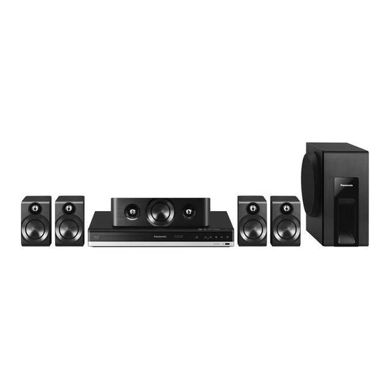
SB-HFS4010
Notes: Please refer to the original service manual for:
• Speaker system SB-HFS4010/HC4010/HW4010, Order No:AD1403015CE
This service information is designed for experienced repair technicians only and is not designed for use by the general
public. It does not contain warnings or cautions to advise non-technical individuals of potential dangers in attempting
to service a product. Products powered by electricity should be serviced or repaired only by experienced professional
technicians. Any attempt to service or repair the product or products dealt with in this service information by anyone else
could result in serious injury or death.
Blu-ray Disc
Remote
SB-HC4010
Control
SB-HW4010
SA-BTT405
WARNING
TM
Home Theater Sound System
SA-BTT405P
Model No.
SA-BTT405PH
SC-BTT405P
SC-BTT405PH
Colour:(K)...........Black Type
© Panasonic Corporation 2014
Unauthorized copying and distribution is a violation of law.
ORDER
NO.AD1404013CE
Advertisement
Table of Contents

Related Manuals for Panasonic SA-BTT405P


Summary of Contents for Panasonic SA-BTT405P
- Page 1 Any attempt to service or repair the product or products dealt with in this service information by anyone else could result in serious injury or death. © Panasonic Corporation 2014 Unauthorized copying and distribution is a violation of law.
-
Page 2: Table Of Contents
TABLE OF CONTENTS PAGE 1 Safety Precautions ----------------------------------------------- 3 1.1. General Guidelines ---------------------------------------- 3 1.2. Leakage Current Cold Check ---------------------------- 3 1.3. Leakage Current Hot Check (See Figure 1.) ------- 3 1.4. Protection Circuitry------------------------------------------ 3 2 Warning -------------------------------------------------------------- 4 2.1. Prevention of Electrostatic Discharge (ESD) to Electrostatically Sensitive (ES) Devices ---------- 4 2.2. -
Page 3: Safety Precautions
1 Safety Precautions 1.1. General Guidelines 1. IMPORTANT SAFETY NOTICE There are special components used in this equipment which are important for safety. These parts are marked by in the Schematic Diagrams, Circuit Board Layout, Exploded Views and Replacement Parts List. It is essential that these critical parts should be replaced with manufacturer’s specified parts to prevent X-RADIATION, shock, fire, or other hazards. -
Page 4: Warning
2 Warning 2.1. Prevention of Electrostatic Discharge (ESD) to Electrostatically Sensitive (ES) Devices Some semiconductor (solid state) devices can be damaged easily by static electricity. Such components commonly are called Electrostatically Sensitive (ES) Devices. Examples of typical ES devices are IC(integrated circuits)and some field-effect transistors and semiconductor “chip”... -
Page 5: Precaution Of Laser Diode
2014 er No N0.50 e 24 200 . INVISIBLE LASER RADIATION WHEN OPEN CAUTION DO NOT STARE INTO BEAM. SA-BTT405P Back of product INVISIBLE LASER RADIATION WHEN OPEN DANGER AVOID DIRECT EXPOSURE TO THE BEAM. SA-BTT405PH Back of product CAUTION ! THIS PRODUCT UTILIZES A LASER. -
Page 6: Static Electricity Protection Measures
2.3. Static Electricity Protection Measures • The laser diode in the traverse unit (optical pick-up) may break down due to potential difference caused by static electricity of clothes or human body. So, be careful of electrostatic breakdown during repair of the traverse unit (optical pick-up). 2.4. -
Page 7: Service Navigation
2. When the home screen is display,Select [Setup] → [Settings] → [System] → [System Information] → [Firmware Version Information]. 3. Firmware Version Information screen is displayed. Occasionally, Panasonic may release updated firmware for this unit that may add or improve the way a feature operates. These updates are available free of charge. - Page 8 3.2.2.2. Updating firmware using the USB device When using the USB device to update the firmware. (When using CD-R instead of USB device, perform same the procedures) 1.Download the latest firmware file of the unit. The latest firmware required for version-up can be downloaded from “Support Information from NWBG/VDBG PAVC”web- sitein “TSN system”.
- Page 9 5.If the TV show the firmware update is complete ( is displayed at LED display). Remove the USB device (or the CD-R) and press the POWER button to turn the unit off. 6.Turn the unit on and the home screen appears the firmware update is completed.
-
Page 10: Specifications
Specifications Power consumption [BTT465] [BTT105] GENERAL Reference Front Surround SPEAKER SECTION Approx. 89 W Power supply AC 220 V to 240 V, 50 Hz Approx. 46 W [BTT465] Super Woofer Full range [BTT405] Centre Subwoofer Front tweeter Dimensions (WkHkD) Power consumption in 430 mm k 55 mm k 322 mm Approx. -
Page 11: Others (Licences)
Settings menu. Standard and VC-1 Standard (“AVC/VC-1 Video”) and/or (ii) At least three (3) years from delivery of this product, Panasonic will decode AVC/VC-1 Video that was encoded by a consumer give to any third party who contacts us at the contact information... -
Page 12: Location Of Controls And Components
5 Location of Controls and Components Control reference guide Turn the unit on and off Select title numbers, etc./Enter numbers Cancel Select Bluetooth /Enable pairing ( ® Select an audio or video source Basic playback control buttons ( Select preset radio stations ( Show the status messages ( Show Pop-up Menu/Top Menu ( 10 [ ,... - Page 13 Main unit (Front) 5 6 7 Disc tray Stop Display Start play Unit’s display list USB port Remote control signal sensor Standby/on switch ( /I) Distance: Within approx. 7 m (23 feet). Press to switch the unit from on to standby Angle: Approx.
-
Page 14: Installation Instructions
6 Installation Instructions Turn off all equipment before connection and read the appropriate operating instructions. Do not connect the AC power supply cord until all other connections are completed. 6.1. Speaker Connection Connect the speaker cables to the terminals of the same color. 6.2. -
Page 15: Operating Instruction
7 Operating Instruction 7.1. Take out the Disc from Drive Unit when the Disc cannot be ejected by the OPEN/CLOSE button 7.1.1. Forcible Disc Eject. 7.1.2. When the Disc Eject can not be done. 1. Turn off the power and pull out AC cord. 2. -
Page 16: Multiple Pressing Function
8 Multiple Pressing Function 8 Multiple Pressing Function 8.1. About the Multiple Pressing of the Unit’s Remote Control The remote control which included this unit is possible pressing multiple buttons simultaneously (Multiple Pressing function), 8.1. About the Multiple Pressing of the Unit’s Remote Control andcan operate for the customer’s initial settings and the Service Mode, etc. - Page 17 8.2.1. Open Mode (Remote Cont. Buttons: [OK] [Yellow] [Blue]). 8.2.1. Open Mode (Remote Cont. Buttons: [OK] [Yellow] [Blue])
- Page 18 8.2.2. Privately Mode 1 (Remote Cont. Buttons: [6] [7] [Yellow]). 8.2.2. Privately Mode 1 (Remote Cont. Buttons: [6] [7] [Yellow]) 8.2.2. Privately Mode 1 (Remote Cont. Buttons: [6] [7] [Yellow]) 8.2.3. Privately Mode 2 (Remote Cont. Buttons: [5] [9] [Red]) 8.2.3.
-
Page 19: Service Mode
9 Service Mode 9.1. About the Service Mode Informations necessary for service can be displayed. 9.1.1. How to enter the Service Mode. 9.1.2. How to exit the Service Mode. Press and hold the [Power] button (remote control or unit). •The Service Mode is terminated and automatically turns the unit off. -
Page 20: Service Mode List
9.2. Service Mode List The display of information to each command is as follows. Note: Do not use it excluding the designated command. -
Page 21: Self-Diagnostics Functions
9.3. Self-Diagnostics Functions 9.3.1. Self-Diagnostics Functions. Self-Diagnosis Function provides information for errors to service personnel by Self-Diagnosis Display when any error has occurred. U** , H** and F** are stored in memory and held. You can check last error code by transmitting [0] [1] of Remote Control in Service Mode. Automatic Display on FL will be cancelled when the power is turned off or AC input is turned off during self-diagnosis display is... -
Page 22: Troubleshooting Guide
10 Troubleshooting Guide 10.1. About Operation of Set The page number in this chapter does not show the page number of this service manual. -
Page 23: After Servicing
If your wireless network is encrypted; Firmware updates Enter your encryption key (password). ≥ You can switch between capital and lower case Occasionally, Panasonic may release updated ≥ Refer to the owner’s manuals of the hub or router. 10.2. After Servicing letters by pressing the “Shift”... - Page 24 Symptom -1 Symptom -2 Symptom -1 VOLTAGE DATA(measurement value) Disc Tray Can not OPEN or CLOSE No power REF.NO. PIN NO. XP10 Check AC inlet unit. Exchange the Check the (cutting or damage…etc.) AC inlet unit OPEN/CLOSE SW. Exchange the (Break or click feeling ...etc.) Front P.C.B.
- Page 25 Symptom -2 Disc Tray Can not OPEN or CLOSE Exchange the Check the tc.) AC inlet unt OPEN/CLOSE SW. Exchange the (Break or click feeling ...etc.) Front P.C.B. Exchange the tc.) AC cord Check the Front Panel Exchange Front Panel (Broken ...etc.) .
- Page 26 VOLTAGE DATA (measurement value) Symptom -3 Symptom -4 Symptom -3 REF.NO. PIN NO. Remote Control does not work No LED Display/Keys does not work 3.3V 3.3V 1.7V PIO9 Check the battery of Exchange the Check the Digital P.C.B. PIO11 Exchange the the Remote Control battery connector XP9 voltage.*2...
- Page 27 VOLTAGE DATA (measurement value) Symptom -4 REF.NO. PIN NO. Remote Control does not work 3.3V 3.3V 1.7V PIO9 Check the battery of Exchange the PIO11 ange the the Remote Control battery l P.C.B. PIO13 3.3V 3.3V Check the Digital P.C.B. Exchange the connector XP9 voltage.*2 Digital P.C.B.
- Page 28 Symptom -5 Symptom -6 No Picture No Sound Check the Input Source Check the Input Source Choose Correct Source Choose Correct Source Check the Connection Check the Connection reconnect correctly reconnect correctly Exchange the Speaker Box Check the Speaker Box Check the Setup Setup Deepclolor and of HOME menu...
- Page 29 Symptom -7 Symptom -8 NFC Error Bluetooth Error Reset Bluetooth Reset Bluetooth Setup Correct Setup Correct Check the NFC P.C.B Check the NFC P.C.B from Setup Menu from Setup Menu Exchange the Exchange the Front PCB Connetor *4 Front PCB Connetor *4 NFC P.C.B.
- Page 30 Symptom -9 Can not play disc Change to other Change to other discs and try discs and try Disc error Disc error playback again playback again Check the the Exchange the Mechanism unit Mechanism unit Exchange the Digital P.C.B. Symptom -10 Fan does not work Set the VOL to 100 Set the VOL to 100...
-
Page 31: Wiring Connection And Voltage Data
11 Wiring Connection and Voltage Data ARC IN OPTICAL IN HDMI OUT PVDD(25.5V) PVDD(25.5V) PVDD(25.5V) Source Switch1 Power Stage Power Stage Power Stage Crystal 74LVC1G3157 TI5342A TI5342A TI5342A PCON Audio Processor TAS5538DGG USB_VCCF TPIC_COMMON USBP1 TPIC_U USBM1 MPEG DECODER MPEG DECODER TPIC_V MT8561 MOTOR... - Page 32 VOLTAGE DATA (measurement value) PIN NO. VALUE PIN NO. VALUE PIN NO. VALUE (See Fig. 2) 3.3V 3.3V 1.7V 25.6V 25.6V 25.6V 3.4V PIN NO. VALUE 3.4V 5.1V PIN NO. VALUE 5.3V 3.3V 3.5V 3.4V PIN NO. VALUE 3.4V (See Fig. 1) (See Fig.
-
Page 33: Disassembly And Assembly Instructions
12 Disassembly and Assembly Instructions 12.1. Disassembly Flow Chart The following chart is the procedure of disassembling the casing and inside parts for internal inspection when carrying out the servicing. To assemble the unit, reverse the steps shown in the chart below. 12.2. -
Page 34: Disassembly Procedure
12.3. Disassembly Procedure 12.3.2.2. Front Panel Unit 12.3. Disassembly Procedure 12.3.2.2. Front Panel Unit 12.3. Disassembly Procedure 1. Detach the lead wires fixed at hooking part of the Body 12.3.2.2. Front Panel Unit 12.3.1. Top Panel Chassis. 1. Detach the lead wires fixed at hooking part of the Body 1.Disconnect the connector (A) and FFC cable. - Page 35 12.3.4. Body Chassis 4. Pull out the NFC P.C.B. Unit. 12.3.4. Body Chassis 4. Pull out the NFC P.C.B. Unit.. 1. Detach the lead wires fixed at hooking part of the Body 1.Detach the lead wires fixed at hooking part of the Body Chassis.
- Page 36 12.3.6. Fan Motor Unit 12.3.7. Digital P.C.B. Unit 1. Remove the 2 screws (A). 12.3.6. Fan Motor Unit 12.3.7. Digital P.C.B. Unit 12.3.6. Fan Motor Unit 12.3.7. Digital P.C.B.Unit 2. Remove the 2 screws (A), then remove the Fan Motor 1.
- Page 37 12.3.7. Digital P.C.B. Unit 12.3.8. Mechanism Unit 12.3.9. AC Inlet Unit 1.Press tab (A) on the AC cord connector simultaneously Motor in the direction of arrows to pull the AC cord out from the Back Panel. AC Inlet Unit 1. Remove the 4 screws (A) and screw (B). 2.
-
Page 38: Measurements And Adjustments
Measurements and Adjustments 13.1. When Replacing the Mechanism Unit and/or Digital P.C.B. Unit When replacing the mechanism unit, Digital P.C.B. Unit or both, the drive adjustment is required. The adjustment is performs reading QR coded adjustment value by web camera and writing the value to Digital P.C.B. Unit. There are 2 method for adjustment value writing: (1) Using PC: "Using PC Method"... - Page 39 13.1.2. Using PC method 4. Click file name (Rpower_2.9.71(KEM480)_for Pana) and Execute Adjustment Software (FERpower.exe) on PC. 1. Set the serial card (RFKZ0139) switch to “OFF” position, then connect to PC’s serial port. 5. Set ComPort matching to the available PC Port No.. 2.
- Page 40 8. Click “QR Reader” button. 10. Turn on the Main Unit. 11. Select QR code and copy by using “CTRL” + “C” and then paste to “Bar Code” field by using “CTRL” + “V”. Then click “Write (F2)” button. 9. Read QR code on the Mechanism Unit bottom side. 12.
- Page 41 13.1.3. Using Remote control Method 13. NG example (NG is lit red) • ComPort setting is wrong. • Perform the Step 6 to Step 10 of “13.1.2. Using PC Method” (ComPort No. selection is wrong and/or Baud Rate to read QR code of Mechanism Unit. Or read QR code using selection is wrong.) smartphone’s QR code reader.
- Page 42 5. Press cursor key to select “Enter 1D barcode by remotecon...”, then press “OK” key. 6. “Input 1D barcode data” screen is displayed. Pressing cursor key to select character, then pressing “OK” key to decide and enter selected character. If entering 64 character of barcode finished, press “RETURN”...
-
Page 43: When Replacing The Front P.c.b.unit And/Or Nfc P.c.b. Unit
13.2. When replacing the Front P.C.B. Unit and/or NFC P.C.B. Unit When replacing the Front P.C.B. Unit, NFC P.C.B. Unit or both, the MAC address of bluetooth module on Front P.C.B. Unit 13.2. When Replacing the Front P.C.B. Unit and/or NFC P.C.B. Unit registration to NFC tag on NFC P.C.B. - Page 44 4. Tap the “TCL BT TAG writer V1.4.apk” your Android device 6. When the installation is finished,below icon will appear on has received. the Android device. 4. Tap APK file of NFC tag writing software which received 6. Open the [Settings] screen of Android device again, then to install.
- Page 45 (This operation required only once after the “TCL BT TAG 2. Confirm the Module type in the label on the Bluetooth can delete it and input “Panasonic BTT”. (Once you do it enter it to the second half of [MAC ADDRESS] field.
-
Page 46: Caution For Replacing Parts
13.3. Caution for Replacing Parts 13.3.1. Standard Inspect Specifications after Repairs After repairing Digital P.C.B. Unit and Mechanism Unit, it is recommended to perform the following inspection to ensure normaloperation of main unit. Procedures Item to Check Turn on the power, and confirm items pointed out. Items pointed out should reappear. -
Page 47: Exploded View And Replacement Parts List
14 Exploded View and Replacement Parts List 14.1. Replacement Parts List Notes: *Important safety notice: mark have special characteristics important for safety. Components identified by When replacing any of components, be sure to use only manufacture’s specified parts shown in the parts list. *Parts marked with [PJM] in the remarks column are supplied by PAVCJM,others are supplied by PHK. -
Page 48: Casing Parts & Mechanism Section
14.2. Casing Parts & Mechanism Section... -
Page 49: Packing & Accessories Section
14.3. Packing & Accessories Section ACCESSORIES BAG OI BOOK QSG OI PREPARATIOPN VER.) FM INDOOR ANTENNA PLUG ADAPTOR (FOR PH ONLY) SC-BTT405 BATTERIES (NOT SUPPLIED) A7 SPEAKER STICKERS A1 Remote Control A4 AC CORD P4 Mirror Bag (FOR P ONLY) A4 AC CORD (FOR PH ONLY) Speaker Connection...