Canon 1000 Service Manual
Color laser copier
Hide thumbs
Also See for 1000:
- User manual (278 pages) ,
- Specifications (4 pages) ,
- Parts list (89 pages)

Related Manuals for Canon 1000


Summary of Contents for Canon 1000
- Page 1 COLOR LASER COPIER 1000/1000S/3100 REVSION 2 FY8-13E3-020 MAY 2001 COPYRIGHT © 2001 CANON INC. CANON CLC1000/1000S/3100 REV.2 MAY 2001 PRINTED IN JAPAN (IMPRIME AU JAPON)
- Page 2 IMPORTANT THE INFORMATION CONTAINED HEREIN IS PUBLISHED BY CANON, INC., JAPAN, AND IS FOR REFERENCE USE ONLY. SPECIFICATIONS AND OTHER INFORMATION CONTAINED HEREIN MAY VARY SLIGHTLY FROM ACTUAL MACHINE VALUES OR THOSE FOUND IN ADVERTISING AND OTHER PRINTED MATTER. ANY QUESTIONS REGARDING INFORMATION CONTAINED HEREIN SHOULD BE DIRECTED TO THE COPIER SERVICE DEPARTMENT OF THE SALES COMPANY.
- Page 3 INTRODUCTION This Service Manual provides basic facts and figures needed to service the plain-paper Color Laser Copier 1000/1000S/3100 in the field. The Color Laser Copier 1000/1000S/3100 may be configured with the following system devices: Preview Monitor/Preview Monitor Board RDF-E1 Editor F1...
- Page 4 All service persons are expected to be thoroughly familiar with the contents of this Service Manual, the Service Handbook, and Service Information bulletins and be ready to respond to the needs of the user promptly. COPYRIGHT © 2001 CANON INC. CANON CLC1000/1000S/3100 REV.2 MAY 2001 PRINTED IN JAPAN (IMPRIME AU JAPON)
- Page 5 All service persons are expected to have a good understanding of the contents of this Service Manual and all relevant Service Information bulletins and be able to identify and isolate faults in the machine. COPYRIGHT © 2001 CANON INC. CLC1000/1000S/3100 REV.2 MAY 2001 PRINTED IN JAPAN (IMPRIME AU JAPON)
-
Page 6: System Configuration
[10] PS-IPU III [11] IPU II [12] Film Scanner III [13] Copy Data Controller A1 (not available in some areas) [14] ED Board A1 COPYRIGHT © 2001 CANON INC. CANON CLC1000/1000S/3100 REV.2 MAY 2001 PRINTED IN JAPAN (IMPRIME AU JAPON) -
Page 7: Table Of Contents
G. Image Position Correction ....3-74 Scanning Lamp ....... 3-34 IMAGE FORMATION SYSTEM ..... 3-84 III. IMAGE PROCESSING SYSTEM ..3-36 A. Outline ..........3-84 COPYRIGHT © 2001 CANON INC. CANON CLC1000/1000S/3100 REV.2 MAY 2001 PRINTED IN JAPAN (IMPRIME AU JAPON) - Page 8 C. Fixing Lower Cleaning Assembly .. 4-103 C. Replacing the Separation Paper Fixing Oil Application Unit ..... 4-105 Guide Static Eliminating Wire ..4-55 ELECTRICAL SYSTEM ....... 4-107 COPYRIGHT © 2001 CANON INC. CANON CLC1000/1000S/3100 REV.2 MAY 2001 PRINTED IN JAPAN (IMPRIME AU JAPON)
- Page 9 Electrical ADJUSTMENT ....7-42 E. Fans ..........7-164 III. TROUBLESHOOTING IMAGE Motors ........... 7-166 PROBLEMS ........... 7-52 G. PCBs ..........7-168 A. Initial Checks ........7-52 COPYRIGHT © 2001 CANON INC. CANON CLC1000/1000S/3100 REV.2 MAY 2001 PRINTED IN JAPAN (IMPRIME AU JAPON)
- Page 10 GENERAL CIRCUIT DIAGRAM ... A-11 HVT CIRCUIT DIAGRAM ..... A-70 DC CONTROLLER CIRCUIT SPECIAL TOOLS ........A-82 DIAGRAM ..........A-15 SOLVENTS AND OILS ......A-84 viii COPYRIGHT © 2001 CANON INC. CANON CLC1000/1000S/3100 REV.2 MAY 2001 PRINTED IN JAPAN (IMPRIME AU JAPON)
- Page 11 D. Others ..........1-5 B. Cross Section ........1-13 III. LASER AND SAFETY MEASURES ..1-9 C. Control Panel ........1-15 A. DHHS ..........1-9 COPYRIGHT © 2001 CANON INC. CANON CLC1000/1000S/3100 REV.2 MAY 2001 PRINTED IN JAPAN (IMPRIME AU JAPON)
-
Page 13: Chapter 1 General Description
Board A1 provides such complex creative functions as framing, gradation, and freehand. Full line-up of options. A large number of options are designed for the CLC1000, including the Preview Monitor, RDF, and IPU-II. COPYRIGHT © 2001 CANON INC. CANON CLC1000/1000S/3100 REV.2 MAY 2001 PRINTED IN JAPAN (IMPRIME AU JAPON) -
Page 14: Specifications
Static retention (concurrent with Y transfer) Transfer Blade (transfer belt) Separation Static Drum Cleaning Blade Fixing Heat roller (700 W, upper; 500 W, lower) Table 1-202 COPYRIGHT © 2001 CANON INC. CANON CLC1000/1000S/3100 REV.2 MAY 2001 PRINTED IN JAPAN (IMPRIME AU JAPON) -
Page 15: Performance
Trailing edge: 2.5 mm ±1.5 mm Trailing edge: 2.5 mm ±2.0 mm Main scanning direction 400 dpi Sub scanning direction 400 lpi Table 1-203 COPYRIGHT © 2001 CANON INC. CANON CLC1000/1000S/3100 REV.2 MAY 2001 PRINTED IN JAPAN (IMPRIME AU JAPON) - Page 16 Text/photo level Adjustment of text/photo separation (7 steps) Zoom fine adjustment Provided Cleaning Provided Transparency holder memory Provided Thin paper source memory Provided Table 1-203 COPYRIGHT © 2001 CANON INC. CANON CLC1000/1000S/3100 REV.2 MAY 2001 PRINTED IN JAPAN (IMPRIME AU JAPON)
-
Page 17: Others
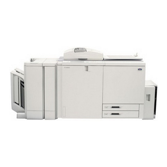
Avoid direct rays of the sun. Dimensions See Figure 1-201. Weight 486.7 kg (body only) Copyboard (3.7 kg) Editor (4.9 kg) Paper Deck (25.5 kg) Table 1-205 COPYRIGHT © 2001 CANON INC. CANON CLC1000/1000S/3100 REV.2 MAY 2001 PRINTED IN JAPAN (IMPRIME AU JAPON) - Page 18 (w/ projector) 2013mm (w/ paper deck) 2476mm (w/ sorter) Height 1000 mm (w/ copyboard cover) 1172 mm (w/ RDF-E1) 1422 mm (w/ projector) Figure 1-201 COPYRIGHT © 2001 CANON INC. CANON CLC1000/1000S/3100 REV.2 MAY 2001 PRINTED IN JAPAN (IMPRIME AU JAPON)
- Page 19 B4 → B5R B5R → B4 B4 → A4R A5 → A3 0.815 2.000 A3 → B4 0.865 — 4.000 A4R → B5R Table 1-206 COPYRIGHT © 2001 CANON INC. CANON CLC1000/1000S/3100 REV.2 MAY 2001 PRINTED IN JAPAN (IMPRIME AU JAPON)
- Page 20 A higher fixing speed decreases the shine, producing a matte effect. On the other hand, a lower fixing speed increases the shine, producing a glossy effect. COPYRIGHT © 2001 CANON INC. CANON CLC1000/1000S/3100 REV.2 MAY 2001 PRINTED IN JAPAN (IMPRIME AU JAPON)
-
Page 21: Laser And Safety Measures
LASER KLASSE 1 PRODUCTO LASER DE CLASE 1 APPARECCHIO LASER DI CLASSE 1 IN ACCORDO CON LA NORMA CEI 76-2 Figure 1-301 COPYRIGHT © 2001 CANON INC. CANON CLC1000/1000S/3100 REV.2 MAY 2001 PRINTED IN JAPAN (IMPRIME AU JAPON) -
Page 22: Points To Note When Handling The Laser Unit
LASERSTRÅLNING NÅR DENNA DEL ÅR ÖPPNAD. BETRAKTA EJ STRÅLEN. ADVARSEL! LASER STRÅLING, NÅR DENNE ER ÅBEN. UNDGÅ BESTRÅLING. FS6-8030 ADVARSEL LASERSTRÅLING NÅR DEKSEL ÅPNES. UNNGÅ EKSPONERING FOR STRÅLEN. Figure 1-303 1-10 COPYRIGHT © 2001 CANON INC. CANON CLC1000/1000S/3100 REV.2 MAY 2001 PRINTED IN JAPAN (IMPRIME AU JAPON) -
Page 23: Names Of Parts
Hopper cover (toner supply opening) [10] Cassette 2 Multifeeder [11] Front cover (left) Paper deck (option in Japan) [12] Copy tray Figure 1-401 1-11 COPYRIGHT © 2001 CANON INC. CANON CLC1000/1000S/3100 REV.2 MAY 2001 PRINTED IN JAPAN (IMPRIME AU JAPON) - Page 24 [3] Front cover switch Fixing/delivery/reversing unit [4] Hopper assembly [10] Fixing oil bottle [5] Transfer unit [11] Document holder [6] Duplexing unit Figure 1-402 1-12 COPYRIGHT © 2001 CANON INC. CANON CLC1000/1000S/3100 REV.2 MAY 2001 PRINTED IN JAPAN (IMPRIME AU JAPON)
-
Page 25: Cross Section
[49] [51] [53] [33] [35] [37] [39] [41] [43] [45] [47] [55] [59] [56] [60] [57] [61] [58] [62] [40] [63] Figure 1-403 1-13 COPYRIGHT © 2001 CANON INC. CANON CLC1000/1000S/3100 REV.2 MAY 2001 PRINTED IN JAPAN (IMPRIME AU JAPON) - Page 26 Cassette 2 [44] Duplexing unit [45] Polishing roller [46] Oil removing roller [47] Cassette 1 [48] Pick-up roller [49] Feeding roller [50] Separation roller 1-14 COPYRIGHT © 2001 CANON INC. CANON CLC1000/1000S/3100 REV.2 MAY 2001 PRINTED IN JAPAN (IMPRIME AU JAPON)
-
Page 27: Control Panel
[10] Call key Press it to recall up to three previous copying modes. [11] Pilot lamp Glows green when power is turned on. Table 1-401 1-15 COPYRIGHT © 2001 CANON INC. CANON CLC1000/1000S/3100 REV.2 MAY 2001 PRINTED IN JAPAN (IMPRIME AU JAPON) - Page 28 [1]. • If horizontal, orient it so that the white triangle at the corner is front right [2]. Figure 1-405 1-16 COPYRIGHT © 2001 CANON INC. CANON CLC1000/1000S/3100 REV.2 MAY 2001 PRINTED IN JAPAN (IMPRIME AU JAPON)
-
Page 29: I. Fixing (Step 7)
G. Retention/Transfer (step 5) ....2-6 III. LIMITATIONS ......... 2-12 H. Separation (step 6) ......2-7 A. Outline ..........2-12 Fixing (step 7) ........2-7 B. Characteristics ......... 2-12 COPYRIGHT © 2001 CANON INC. CANON CLC1000/1000S/3100 REV.2 MAY 2001 PRINTED IN JAPAN (IMPRIME AU JAPON) -
Page 31: Chapter 2 Copying Process
Pre-exposure assembly lamp Pre-primary charging Surface assembly potential sensor Developing assembly Photosensitive Photosensitive drum drum cleaner SALT sensor Transfer blade Transfer belt Figure 2-101 COPYRIGHT © 2001 CANON INC. CANON CLC1000/1000S/3100 REV.2 MAY 2001 PRINTED IN JAPAN (IMPRIME AU JAPON) - Page 32 4. Development Delivery Manual feeding 7. Fixing 6. Separation 5. Transfer Registration 5. Retention/transfer Paper deck Duplexing tray Cassette 1 Cassette 2 Figure 2-102 COPYRIGHT © 2001 CANON INC. CANON CLC1000/1000S/3100 REV.2 MAY 2001 PRINTED IN JAPAN (IMPRIME AU JAPON)
-
Page 33: Static Latent Image Formation Block
-500 density. Dark area (white on original) -1000 Pre-exposure Primary charging Image exposure (step 1) (step 2) (step 3) Figure 2-103 COPYRIGHT © 2001 CANON INC. CANON CLC1000/1000S/3100 REV.2 MAY 2001 PRINTED IN JAPAN (IMPRIME AU JAPON) -
Page 34: Primary Charging (Step 2)
4 (development). specific drum surface potential. COPYRIGHT © 2001 CANON INC. CANON CLC1000/1000S/3100 REV.2 MAY 2001 PRINTED IN JAPAN (IMPRIME AU JAPON) -
Page 35: Development (Step 4)
COPYRIGHT © 2001 CANON INC. CANON CLC1000/1000S/3100 REV.2 MAY 2001 PRINTED IN JAPAN (IMPRIME AU JAPON) -
Page 36: Retention/Transfer (Step 5)
(Y), transfer occurs at the same time as when the paper is drawn to the transfer belt by the work of transfer charges. COPYRIGHT © 2001 CANON INC. CANON CLC1000/1000S/3100 REV.2 MAY 2001 PRINTED IN JAPAN (IMPRIME AU JAPON) -
Page 37: Separation (Step 6)
The upper fixing roller is cleaned by a cleaning web, and the lower fixing roller is cleaned by a cleaning web and a cleaning blade. COPYRIGHT © 2001 CANON INC. CANON CLC1000/1000S/3100 REV.2 MAY 2001 PRINTED IN JAPAN (IMPRIME AU JAPON) -
Page 38: Photosensitive Drum Cleaning
The collected toner is moved by the waste toner feeding screw to the rear of the copier and is collected in the waste toner case. COPYRIGHT © 2001 CANON INC. CANON CLC1000/1000S/3100 REV.2 MAY 2001 PRINTED IN JAPAN (IMPRIME AU JAPON) -
Page 39: Auxiliary Process
COPYRIGHT © 2001 CANON INC. CANON CLC1000/1000S/3100 REV.2 MAY 2001 PRINTED IN JAPAN (IMPRIME AU JAPON) -
Page 40: Grounding Roller
*Actually, by applying negative charges. 2-10 COPYRIGHT © 2001 CANON INC. CANON CLC1000/1000S/3100 REV.2 MAY 2001 PRINTED IN JAPAN (IMPRIME AU JAPON) -
Page 41: Transfer Belt Cleaning
Roughens the surface of the transfer belt to prevent adhesion of oil from the transfer belt to the photosensitive drum. And removes paper lint on the transfer belt. 2-11 COPYRIGHT © 2001 CANON INC. CANON CLC1000/1000S/3100 REV.2 MAY 2001 PRINTED IN JAPAN (IMPRIME AU JAPON) -
Page 42: Limitations
These limitations, however, have been solved to a point where they will not present appreciable problems by controlling the image processing by the scanner unit. 2-12 COPYRIGHT © 2001 CANON INC. CANON CLC1000/1000S/3100 REV.2 MAY 2001 PRINTED IN JAPAN (IMPRIME AU JAPON) - Page 43 G. Image Position Correction ....3-74 B. Protection Mechanisms for the IMAGE FORMATION SYSTEM ..... 3-84 Power Supply Circuits ....3-201 A. Outline ..........3-84 COPYRIGHT © 2001 CANON INC. CANON CLC1000/1000S/3100 REV.2 MAY 2001 PRINTED IN JAPAN (IMPRIME AU JAPON)
-
Page 45: Basic Mechanisms
Manual Pre-fixing feeding Pick-up feeding control Holding tray Pre-holding tray feeding Fixing Upper cassette Paper deck Copy tray Lower cassette Pick-up/feeding block Figure 3-101 COPYRIGHT © 2001 CANON INC. CANON CLC1000/1000S/3100 REV.2 MAY 2001 PRINTED IN JAPAN (IMPRIME AU JAPON) -
Page 46: Outline Of Electrical Circuitry
Charging assembly Developing bias Pick-up motor Laser scanner motor, Laser scanner motor driver PCB Paper deck Pre-exposure lamp Motor, Fan, Clutch, Solenoid Figure 3-102 COPYRIGHT © 2001 CANON INC. CANON CLC1000/1000S/3100 REV.2 MAY 2001 PRINTED IN JAPAN (IMPRIME AU JAPON) -
Page 47: Inputs To And Outputs From Major Pcbs
Laser driver M PCB J 1301BK J 1301M Laser M Laser K J 2103 J 2105 BD-K PCB BD-M PCB J 3251M J 3251BK Figure 3-103 COPYRIGHT © 2001 CANON INC. CANON CLC1000/1000S/3100 REV.2 MAY 2001 PRINTED IN JAPAN (IMPRIME AU JAPON) - Page 48 4 FM13D* FM13 turns ON. Lamp regulator (CVR) J 6230 Scanning lamp See Chapter 3. (original exposure system) J 1305A Figure 3-104 COPYRIGHT © 2001 CANON INC. CANON CLC1000/1000S/3100 REV.2 MAY 2001 PRINTED IN JAPAN (IMPRIME AU JAPON)
- Page 49 See the Service Manual To projector for the projector. J 1305A See the Service Manual To RF-E1 for the RF-E1. J 1306B Figure 3-105 COPYRIGHT © 2001 CANON INC. CANON CLC1000/1000S/3100 REV.2 MAY 2001 PRINTED IN JAPAN (IMPRIME AU JAPON)
- Page 50 J 2214B - 6 When paper is at PS9, '1'. Holding tray front feeding (when light-blocking plate is at PS9) PS9DT sensor 2 PS 9 Figure 3-106 COPYRIGHT © 2001 CANON INC. CANON CLC1000/1000S/3100 REV.2 MAY 2001 PRINTED IN JAPAN (IMPRIME AU JAPON)
- Page 51 J 6111 - 1 Transfer belt edge When edge detection lever (rear) of PS20DT sensor 4 (rear) transfer belt is at PS20, '1'. PS 20 Figure 3-107 COPYRIGHT © 2001 CANON INC. CANON CLC1000/1000S/3100 REV.2 MAY 2001 PRINTED IN JAPAN (IMPRIME AU JAPON)
- Page 52 J2224A - 4 Holding tray When paper is at PS30, '1'. PS 30DT paper sensor 1 (when light-blocking plate is at PS30) PS 30 Figure 3-108 COPYRIGHT © 2001 CANON INC. CANON CLC1000/1000S/3100 REV.2 MAY 2001 PRINTED IN JAPAN (IMPRIME AU JAPON)
- Page 53 PS101 Cassette 1 Detects paper length based on C1SZ0 SEU 1 paper length sensor unit combination of various input signals. C1SZ0 PS102 Figure 3-109 COPYRIGHT © 2001 CANON INC. CANON CLC1000/1000S/3100 REV.2 MAY 2001 PRINTED IN JAPAN (IMPRIME AU JAPON)
- Page 54 C toner level J3401B- 5 CTEPL* sensor TS 7 (lower) J 6337- 3 Bk toner level KTEPL* Hopper relay sensor TS 8 (lower) Figure 3-110 3-10 COPYRIGHT © 2001 CANON INC. CANON CLC1000/1000S/3100 REV.2 MAY 2001 PRINTED IN JAPAN (IMPRIME AU JAPON)
- Page 55 Check in the field not possible. EPC-M CT M Potential sensor (M) J 6224M- 1 J 6219M J 4604L 150V 150V - 15V -15V HVT2-1 Figure 3-111 3-11 COPYRIGHT © 2001 CANON INC. CANON CLC1000/1000S/3100 REV.2 MAY 2001 PRINTED IN JAPAN (IMPRIME AU JAPON)
- Page 56 J 6063 J 2955B-6 J 2207B-10 EVRMT Check in the field not possible. EVHUM Environment sensor J 6224Y- 6 EVTEMP J 6099Y Figure 3-112 3-12 COPYRIGHT © 2001 CANON INC. CANON CLC1000/1000S/3100 REV.2 MAY 2001 PRINTED IN JAPAN (IMPRIME AU JAPON)
- Page 57 J 2853F See Chapter 3. correction PCB (laser exposure) (rear) J 2951R LED rear PCB for pattern reading J 2204 J 2854R Figure 3-113 3-13 COPYRIGHT © 2001 CANON INC. CANON CLC1000/1000S/3100 REV.2 MAY 2001 PRINTED IN JAPAN (IMPRIME AU JAPON)
- Page 58 When '0', upper fixing heater turns ON. LHON When '0', lower fixing heater turns ON. AC input Fixing Lower for web web drive motor motor Figure 3-114 3-14 COPYRIGHT © 2001 CANON INC. CANON CLC1000/1000S/3100 REV.2 MAY 2001 PRINTED IN JAPAN (IMPRIME AU JAPON)
- Page 59 J 6104 -1 Bk transfer blade with transfer belt) solenoid SL 7Bk SL7KDR* When '0', SL7BDR turns ON. (transfer blade leaves transfer belt) Figure 3-115 3-15 COPYRIGHT © 2001 CANON INC. CANON CLC1000/1000S/3100 REV.2 MAY 2001 PRINTED IN JAPAN (IMPRIME AU JAPON)
- Page 60 When '0', SL13 turns ON. J 6053 J 2951 J 2207A-5 SL 16 Registration releasing solenoid SL16D* When '0', SL13 turns ON. Multifeeder relay PCB Figure 3-116 3-16 COPYRIGHT © 2001 CANON INC. CANON CLC1000/1000S/3100 REV.2 MAY 2001 PRINTED IN JAPAN (IMPRIME AU JAPON)
- Page 61 When '0', CL4 turns ON. (upper) J 6011- 1 Bk toner supply clutch CL 5 (lower) CL5D* When '0', CL5 turns ON. Figure 3-117 3-17 COPYRIGHT © 2001 CANON INC. CANON CLC1000/1000S/3100 REV.2 MAY 2001 PRINTED IN JAPAN (IMPRIME AU JAPON)
- Page 62 CL16D* When '0', CL16 turns ON. J 3701 - 2 J 2226A - 4 Transfer belt lifter clutch CL 17 CL17D* When '0', CL17 turns ON. Figure 3-118 3-18 COPYRIGHT © 2001 CANON INC. CANON CLC1000/1000S/3100 REV.2 MAY 2001 PRINTED IN JAPAN (IMPRIME AU JAPON)
- Page 63 J 6373 - 2 J 2225B - 11 FM 20 Delivery lower cooling fan 2 FM20D* When '0', FM20 turns ON. Figure 3-119 3-19 COPYRIGHT © 2001 CANON INC. CANON CLC1000/1000S/3100 REV.2 MAY 2001 PRINTED IN JAPAN (IMPRIME AU JAPON)
- Page 64 M8-A* Alternates between '1' and '0' correction motor for Bk - 10 M8-B while M8 is rotating. - 12 M8-B* Figure 3-120 3-20 COPYRIGHT © 2001 CANON INC. CANON CLC1000/1000S/3100 REV.2 MAY 2001 PRINTED IN JAPAN (IMPRIME AU JAPON)
- Page 65 J 6100 - 5 J 5329 - 4 DCP1U J2218A-11 M15ON Polishing/oil removing motor M 15 M15PLL See Chapter 3. M15DIR (pick-up/feeding system) Figure 3-121 3-21 COPYRIGHT © 2001 CANON INC. CANON CLC1000/1000S/3100 REV.2 MAY 2001 PRINTED IN JAPAN (IMPRIME AU JAPON)
- Page 66 J2224B- 3 M23-A While M23 is rotating, Duplexing stacking M23-A* M 23 alternates between '1' and '0'. guide motor M23-B M23-B* Figure 3-122 3-22 COPYRIGHT © 2001 CANON INC. CANON CLC1000/1000S/3100 REV.2 MAY 2001 PRINTED IN JAPAN (IMPRIME AU JAPON)
- Page 67 T 4104 HVTR-K HVEL When '1', internal static eliminating Internal static eliminating roller high voltage is generated. T 4105 HVT1 PCB Figure 3-123 3-23 COPYRIGHT © 2001 CANON INC. CANON CLC1000/1000S/3100 REV.2 MAY 2001 PRINTED IN JAPAN (IMPRIME AU JAPON)
- Page 68 J 4703R HVDCEN-M HVDC-M Developing cylinder (Y) HVAC-M When '1', respective J 4703R HVDCEN-Y high voltage is generated. HVDC-Y HVAC-Y HVT3A-R PCB Figure 3-124 3-24 COPYRIGHT © 2001 CANON INC. CANON CLC1000/1000S/3100 REV.2 MAY 2001 PRINTED IN JAPAN (IMPRIME AU JAPON)
- Page 69 When '0', CNT4 turns ON. Counter 5 CNT 5 CNT5D* When '0', CNT5 turns ON. Counter 6 CNT 6 CNT6D* When '0', CNT6 turns ON. Figure 3-125 3-25 COPYRIGHT © 2001 CANON INC. CANON CLC1000/1000S/3100 REV.2 MAY 2001 PRINTED IN JAPAN (IMPRIME AU JAPON)
-
Page 70: Sequence Of Basic Operations
• The fixing temperature means the surface temperature of the fixing roller (reading of the thermistor indicated under ‘ANALOG’ of ‘DISPLAY’ in service mode). 3-26 COPYRIGHT © 2001 CANON INC. CANON CLC1000/1000S/3100 REV.2 MAY 2001 PRINTED IN JAPAN (IMPRIME AU JAPON) - Page 71 From the end of INTR (e.g., Start key) is until the Start key is pressed. pressed or the power switch is turned OFF. Table 3-101 3-27 COPYRIGHT © 2001 CANON INC. CANON CLC1000/1000S/3100 REV.2 MAY 2001 PRINTED IN JAPAN (IMPRIME AU JAPON)
- Page 72 (Image formation starts in relation to a registration signal.) Control in relation to signals other than the registration signal is discussed using separate timing charts. 3-28 COPYRIGHT © 2001 CANON INC. CANON CLC1000/1000S/3100 REV.2 MAY 2001 PRINTED IN JAPAN (IMPRIME AU JAPON)
-
Page 73: Original Exposure System
Figure 3-201 Scanner motor (M29) No. 2 mirror mount Forward No. 1 mirror mount Signal plate Original scanner home position sensor (PS37) Figure 3-202 3-29 COPYRIGHT © 2001 CANON INC. CANON CLC1000/1000S/3100 REV.2 MAY 2001 PRINTED IN JAPAN (IMPRIME AU JAPON) -
Page 74: Sequence Of Basic Operations (Original Exposure System)
High-speed rotation. Standard CW rotation. Shading correction. Original position detection, black original detection, AE measurement. [C] Original scanning. [D] Marking area scanning. Figure 3-203 3-30 COPYRIGHT © 2001 CANON INC. CANON CLC1000/1000S/3100 REV.2 MAY 2001 PRINTED IN JAPAN (IMPRIME AU JAPON) - Page 75 • During CCD adjustment (service mode). PS37 Original leading edge Start position Original HP search at power Shading correction Original detection Original scan Figure 3-204 3-31 COPYRIGHT © 2001 CANON INC. CANON CLC1000/1000S/3100 REV.2 MAY 2001 PRINTED IN JAPAN (IMPRIME AU JAPON)
-
Page 76: Scanner Motor
The circuit cuts the current to the motor by the HOLD-OFF signal while the motor remains at rest during standby to prevent heating of the motor. 3-32 COPYRIGHT © 2001 CANON INC. CANON CLC1000/1000S/3100 REV.2 MAY 2001 PRINTED IN JAPAN (IMPRIME AU JAPON) -
Page 77: Changing The Reproduction Ratio
No. 1 mirror mount Signal plate Scanner home position detection signal (SCHP) Scanner home position sensor (PS37) Scanner motor driver PCB Reader controller PCB Figure 3-206 3-33 COPYRIGHT © 2001 CANON INC. CANON CLC1000/1000S/3100 REV.2 MAY 2001 PRINTED IN JAPAN (IMPRIME AU JAPON) -
Page 78: Controlling The Intensity Of The Scanning Lamp
(LA5) to turn OFF. When LAON=1, the lamp regulator drive circuit turns ON to activate the intensity control circuit, thereby turning ON the scanning lamp (LA5). 3-34 COPYRIGHT © 2001 CANON INC. CANON CLC1000/1000S/3100 REV.2 MAY 2001 PRINTED IN JAPAN (IMPRIME AU JAPON) -
Page 79: Controlling The Intensity Of The
Be sure to execute ‘AUTO-ADJ’ under ‘CCD’ of ‘FUNC’ in service mode whenever you have replaced the scanning lamp or the image processor PCB. 3-35 COPYRIGHT © 2001 CANON INC. CANON CLC1000/1000S/3100 REV.2 MAY 2001 PRINTED IN JAPAN (IMPRIME AU JAPON) -
Page 80: Image Processing System
Preview Monitor Board IP memory PCB Laser exposure system Image processor PCB ED board A1 Y,M,C,Bk To video controller PCB Digital video signal Figure 3-301 3-36 COPYRIGHT © 2001 CANON INC. CANON CLC1000/1000S/3100 REV.2 MAY 2001 PRINTED IN JAPAN (IMPRIME AU JAPON) -
Page 81: Ccd/Ccd Driver
Clock pulses (odd) Transfer block (odd) Output block (odd) CCD shift pulses Light-receiving block Transfer block (even) Output block (even) Clock pulses (even) Figure 3-303 3-37 COPYRIGHT © 2001 CANON INC. CANON CLC1000/1000S/3100 REV.2 MAY 2001 PRINTED IN JAPAN (IMPRIME AU JAPON) -
Page 82: Analog Image Processing
8-bit digital signals (A/D conversion) according to the voltage level and sent to the image processor PCB. 3-38 COPYRIGHT © 2001 CANON INC. CANON CLC1000/1000S/3100 REV.2 MAY 2001 PRINTED IN JAPAN (IMPRIME AU JAPON) -
Page 83: Digital Image Processing
Corrects differences in color space between CLC1000 and IPU or other external device. h. Preview Monitor Board (option) Converts video signals (YMCBk) after image processing into RGB signals for display on a CRT. 3-39 COPYRIGHT © 2001 CANON INC. CANON CLC1000/1000S/3100 REV.2 MAY 2001 PRINTED IN JAPAN (IMPRIME AU JAPON) - Page 84 Y,M,C,Bk Interface Board B1/B2 Y, M, C text Y,M,C,Bk Y,M,C,Bk R,G,B IP memory PCB Preview Monitor Board ED board A1 R,G,B Figure 3-305 3-40 COPYRIGHT © 2001 CANON INC. CANON CLC1000/1000S/3100 REV.2 MAY 2001 PRINTED IN JAPAN (IMPRIME AU JAPON)
- Page 85 Note: The interface mother PCB and the image processor mother PCB are omitted from the block diagram to prevent confusion; blocks with the ∗ mark are explained on pages that follow. Figure 3-306 3-41 COPYRIGHT © 2001 CANON INC. CANON CLC1000/1000S/3100 REV.2 MAY 2001 PRINTED IN JAPAN (IMPRIME AU JAPON)
- Page 87 Measurements are taken each time the Start key is pressed. Original density White Standard white plate Figure 3-309 3-43 COPYRIGHT © 2001 CANON INC. CANON CLC1000/1000S/3100 REV.2 MAY 2001 PRINTED IN JAPAN (IMPRIME AU JAPON)
- Page 88 = 0.8 × (51st line image data) + 0.2 × (52nd line pixel data) 51.2nd line pixel data 3-44 COPYRIGHT © 2001 CANON INC. CANON CLC1000/1000S/3100 REV.2 MAY 2001 PRINTED IN JAPAN (IMPRIME AU JAPON)
- Page 89 If an original is placed at an angle as in the case of Figure 3-313, the rectangle whose diagonal line runs between P and P will be identified as an original. 3-45 COPYRIGHT © 2001 CANON INC. CANON CLC1000/1000S/3100 REV.2 MAY 2001 PRINTED IN JAPAN (IMPRIME AU JAPON)
- Page 90 (RGB), it would be ideal if each filter let through light of a specific range of wavelengths and blocked out light of other wavelengths. Wavelength (nm) Figure 3-318 3-46 COPYRIGHT © 2001 CANON INC. CANON CLC1000/1000S/3100 REV.2 MAY 2001 PRINTED IN JAPAN (IMPRIME AU JAPON)
- Page 91 B. Reproduction ratio/reduction processing Image integration ED board R,G,B Image memory IP memory PCB Images A + B Image processor PCB Figure 3-321 3-47 COPYRIGHT © 2001 CANON INC. CANON CLC1000/1000S/3100 REV.2 MAY 2001 PRINTED IN JAPAN (IMPRIME AU JAPON)
- Page 92 In this block, the hue of a specific pixel is identified. The result of identification may be black, or other color. The Bk signal (explained later) is generated based on the above characteristics. 3-48 COPYRIGHT © 2001 CANON INC. CANON CLC1000/1000S/3100 REV.2 MAY 2001 PRINTED IN JAPAN (IMPRIME AU JAPON)
- Page 93 Ideal value Output value Color reproduction range of printer Color space (hue, vividness, brightness) of original Color reproduction range in photo original Figure 3-323 3-49 COPYRIGHT © 2001 CANON INC. CANON CLC1000/1000S/3100 REV.2 MAY 2001 PRINTED IN JAPAN (IMPRIME AU JAPON)
- Page 94 This way, the image on the back of the copy is removed if the copy is transparent enough to let the back image show through. 3-50 COPYRIGHT © 2001 CANON INC. CANON CLC1000/1000S/3100 REV.2 MAY 2001 PRINTED IN JAPAN (IMPRIME AU JAPON)
- Page 95 Y, M, and C (toner). Reflected Absorbed Reflected Reflected Reflected Absorbed Table 3-301 Transmission through filter Reflection by toner Wavelength (nm) Wavelength (nm) Figure 3-327 Figure 3-328 3-51 COPYRIGHT © 2001 CANON INC. CANON CLC1000/1000S/3100 REV.2 MAY 2001 PRINTED IN JAPAN (IMPRIME AU JAPON)
- Page 96 “text/ printed photo” or “printed photo.” (line/mm) Figure 3-330 3-52 COPYRIGHT © 2001 CANON INC. CANON CLC1000/1000S/3100 REV.2 MAY 2001 PRINTED IN JAPAN (IMPRIME AU JAPON)
- Page 97 Image density Image density Image density 1 pixel 1 pixel 1 pixel a. Original b. Enlargement at 300% c. After correction Figure 3-331 3-53 COPYRIGHT © 2001 CANON INC. CANON CLC1000/1000S/3100 REV.2 MAY 2001 PRINTED IN JAPAN (IMPRIME AU JAPON)
- Page 98 IP memory PCB Image compression Non-compression image memory Image memory (option) Image extension Text signal Y,M,C UCR processing Y,M,C,Bk Y,M,C,Bk Image processor PCB Figure 3-332 3-54 COPYRIGHT © 2001 CANON INC. CANON CLC1000/1000S/3100 REV.2 MAY 2001 PRINTED IN JAPAN (IMPRIME AU JAPON)
-
Page 99: Characteristics
UCR amount to less than 100%. This processing is executed for each pixel. Figure 3-335 3-55 COPYRIGHT © 2001 CANON INC. CANON CLC1000/1000S/3100 REV.2 MAY 2001 PRINTED IN JAPAN (IMPRIME AU JAPON) - Page 100 Y component of M toner. Real red could be reproduced by removing the Y component from M toner (masking) in advance. This block makes such correction by masking the excess component in each toner. 3-56 COPYRIGHT © 2001 CANON INC. CANON CLC1000/1000S/3100 REV.2 MAY 2001 PRINTED IN JAPAN (IMPRIME AU JAPON)
- Page 101 Main scanning direction White 0 White 0 After output After output Figure 3-338 Sharpness Mode Set to Weak Figure 3-339 Sharpness Mode Set to Strong 3-57 COPYRIGHT © 2001 CANON INC. CANON CLC1000/1000S/3100 REV.2 MAY 2001 PRINTED IN JAPAN (IMPRIME AU JAPON)
- Page 102 R,G,B Color data (registered color, selected from the color palette) To image processor PCB in the bit map memory is sent. Figure 3-340 3-58 COPYRIGHT © 2001 CANON INC. CANON CLC1000/1000S/3100 REV.2 MAY 2001 PRINTED IN JAPAN (IMPRIME AU JAPON)
- Page 103 Color conversion Bit map data generation Text data Converted into binary data to generate text data Bit map memory Color editing Figure 3-342 3-59 COPYRIGHT © 2001 CANON INC. CANON CLC1000/1000S/3100 REV.2 MAY 2001 PRINTED IN JAPAN (IMPRIME AU JAPON)
- Page 104 If text mode is selected for item e., a curve that enables reproduction of dark text without risking fogging will be selected (Figure 3-344). Copy density Copy density Dark Text mode Light Original density Original density Figure 3-343 Figure 3-344 3-60 COPYRIGHT © 2001 CANON INC. CANON CLC1000/1000S/3100 REV.2 MAY 2001 PRINTED IN JAPAN (IMPRIME AU JAPON)
- Page 105 The area image generation block generates image data for such items as an area frame to be displayed on the CRT; the initial data and the post-edit data are integrated and displayed on the CRT. 3-61 COPYRIGHT © 2001 CANON INC. CANON CLC1000/1000S/3100 REV.2 MAY 2001 PRINTED IN JAPAN (IMPRIME AU JAPON)
-
Page 106: Outline
The laser beam hits and scans the negatively charged photosensitive drum (Figure 3-401) to form a static latent image on the photosensitive drum. 3-62 COPYRIGHT © 2001 CANON INC. CANON CLC1000/1000S/3100 REV.2 MAY 2001 PRINTED IN JAPAN (IMPRIME AU JAPON) - Page 107 C/Bk, the laser beam scans the photosensitive drums in the opposite directions as shown in Figure 3-403. Rear Bk drum C drum M drum Front Y drum Figure 3-403 3-63 COPYRIGHT © 2001 CANON INC. CANON CLC1000/1000S/3100 REV.2 MAY 2001 PRINTED IN JAPAN (IMPRIME AU JAPON)
-
Page 108: Sequence Of Operations (Laser Exposure System)
1 scan BD signal PWM activation Bk laser 00 activation Full activation Full activation 00 activation (*1) if only executed SALT control Figure 3-404 3-64 COPYRIGHT © 2001 CANON INC. CANON CLC1000/1000S/3100 REV.2 MAY 2001 PRINTED IN JAPAN (IMPRIME AU JAPON) -
Page 109: Laser Scanner Motor
‘E110’ on the control panel. Laser scanner motor driver SMRDY* Speed control circuit SMON* Laser scanner motor DC power supply PCB Figure 3-405 3-65 COPYRIGHT © 2001 CANON INC. CANON CLC1000/1000S/3100 REV.2 MAY 2001 PRINTED IN JAPAN (IMPRIME AU JAPON) -
Page 110: Generating The Bd Signal
Video controller PCB BD signal BD detection Y,M,C,K Video signal Main scanning synchronization Video signal Y,M,C,Bk Video signal Main scanning synchronization Figure 3-407 3-66 COPYRIGHT © 2001 CANON INC. CANON CLC1000/1000S/3100 REV.2 MAY 2001 PRINTED IN JAPAN (IMPRIME AU JAPON) -
Page 111: Outline
Video signal Test pattern Main scanning Sub scanning generation synchronization Read signal sync control Y,M,C,Bk Video signal Y,M,C,Bk Video data counter Figure 3-408 3-67 COPYRIGHT © 2001 CANON INC. CANON CLC1000/1000S/3100 REV.2 MAY 2001 PRINTED IN JAPAN (IMPRIME AU JAPON) - Page 112 Y video signal (YVD) Y BD signal (YBD) Y main scanning sync signal (YSYNC*) Y read enable signal (YRE*) Y video signal (YVD) Figure 3-410 3-68 COPYRIGHT © 2001 CANON INC. CANON CLC1000/1000S/3100 REV.2 MAY 2001 PRINTED IN JAPAN (IMPRIME AU JAPON)
- Page 113 M read enable signal (MMRE) Paper length (feeding direction) M print enable signal (MPE) Image area M print area signal (MFRM) Figure 3-412 3-69 COPYRIGHT © 2001 CANON INC. CANON CLC1000/1000S/3100 REV.2 MAY 2001 PRINTED IN JAPAN (IMPRIME AU JAPON)
-
Page 114: Density Correction
Density correction Y,M,C,Bk Figure 3-415 The video data (YMCBk) is corrected against the correction curve for correction and sent to the laser driver. 3-70 COPYRIGHT © 2001 CANON INC. CANON CLC1000/1000S/3100 REV.2 MAY 2001 PRINTED IN JAPAN (IMPRIME AU JAPON) - Page 115 RAM for gamma correction. The selected video data is read from the RAM and sent to the laser driver. For how to use the test patterns which are generated and sample images, see chapter 7, Troubleshooting image problems. 3-71 COPYRIGHT © 2001 CANON INC. CANON CLC1000/1000S/3100 REV.2 MAY 2001 PRINTED IN JAPAN (IMPRIME AU JAPON)
-
Page 116: Laser Driver
Signal generation for 200 lines/ 266 lines Mode signal Laser power adjustment PCB Error signal Intensity monitor Activation current generation Laser power setting Figure 3-417 3-72 COPYRIGHT © 2001 CANON INC. CANON CLC1000/1000S/3100 REV.2 MAY 2001 PRINTED IN JAPAN (IMPRIME AU JAPON) - Page 117 (E100-xx02). Point of activation Current Activation current ON current Intensity Lower limit Point of activation Current Activation current current Figure 3-419 3-73 COPYRIGHT © 2001 CANON INC. CANON CLC1000/1000S/3100 REV.2 MAY 2001 PRINTED IN JAPAN (IMPRIME AU JAPON)
-
Page 118: Image Position Correction
Feeding direction Discrepancy in main Discrepancy in sub scanning direction scanning direction Feeding direction Feeding direction Angle Discrepancy in reproduction ratio Figure 3-420 3-74 COPYRIGHT © 2001 CANON INC. CANON CLC1000/1000S/3100 REV.2 MAY 2001 PRINTED IN JAPAN (IMPRIME AU JAPON) - Page 119 Center coordinates for CCD computation Correction data generation Video controller Laser unit Slant correction motor M3/M6/M8 Reproduction ratio correction motor M2/M5/M7 Figure 3-421 3-75 COPYRIGHT © 2001 CANON INC. CANON CLC1000/1000S/3100 REV.2 MAY 2001 PRINTED IN JAPAN (IMPRIME AU JAPON)
- Page 120 The Y, M, C, and Bk patterns are as shown in Reading (CCD) Figure 3-423. 256th pixels Feeding direction 1st pixel Figure 3-423 3-76 COPYRIGHT © 2001 CANON INC. CANON CLC1000/1000S/3100 REV.2 MAY 2001 PRINTED IN JAPAN (IMPRIME AU JAPON)
- Page 121 130th line. CCD array 256th pixel 128th pixel Feeding direction 0th pixel Accumulated value 0line 256th line 130th line Figure 3-425 3-77 COPYRIGHT © 2001 CANON INC. CANON CLC1000/1000S/3100 REV.2 MAY 2001 PRINTED IN JAPAN (IMPRIME AU JAPON)
- Page 122 C image print enable signal (CPE) Drum-to-drum distance + 21mm Bk image print enable signal (BkPE) Pattern read signal (CCDRD) Figure 3-426 Figure 3-427 3-78 COPYRIGHT © 2001 CANON INC. CANON CLC1000/1000S/3100 REV.2 MAY 2001 PRINTED IN JAPAN (IMPRIME AU JAPON)
- Page 123 ‘E194-0001’ will be indicated on the control panel. If the shutter close sensor does not detect the light-blocking plate when the shutter must close, ‘E194-0002’ will be indicated on the control panel. 3-79 COPYRIGHT © 2001 CANON INC. CANON CLC1000/1000S/3100 REV.2 MAY 2001 PRINTED IN JAPAN (IMPRIME AU JAPON)
- Page 124 In the case of Figure 3-430, the image position correction mirror is rotated in the direction shown in Figure 3-431 so that the scanning angle will be horizontal. Figure 3-431 3-80 COPYRIGHT © 2001 CANON INC. CANON CLC1000/1000S/3100 REV.2 MAY 2001 PRINTED IN JAPAN (IMPRIME AU JAPON)
- Page 125 In the case of Figure 3-432, the length of the optical path is increased, thereby increasing the width of scanning. Y drum Image position correction mirror Polygon mirror Figure 3-433 3-81 COPYRIGHT © 2001 CANON INC. CANON CLC1000/1000S/3100 REV.2 MAY 2001 PRINTED IN JAPAN (IMPRIME AU JAPON)
- Page 126 Video signal Memory for main scanning sync (FIFO) The read timing is varied at points indicated by broad arrows. Figure 3-436 3-82 COPYRIGHT © 2001 CANON INC. CANON CLC1000/1000S/3100 REV.2 MAY 2001 PRINTED IN JAPAN (IMPRIME AU JAPON)
- Page 127 Y read enable signal (YMRE) Paper length (feeding direction) Y print enable signal (YPE) Image area Y print area signal (YFRM) Figure 3-438 3-83 COPYRIGHT © 2001 CANON INC. CANON CLC1000/1000S/3100 REV.2 MAY 2001 PRINTED IN JAPAN (IMPRIME AU JAPON)
-
Page 128: Image Formation System
DC controller PCB Environment sensor HVT2 HVT3 Potential sensor Toner supply clutch Laser output Photosensitive drum PASCAL SALT sensor Color toner density sensor Figure 3-501 3-84 COPYRIGHT © 2001 CANON INC. CANON CLC1000/1000S/3100 REV.2 MAY 2001 PRINTED IN JAPAN (IMPRIME AU JAPON) - Page 129 Separation charging assembly HVT1 Transfer blade Pre-fixing charging Internal static eliminating roller assembly DC bias Transfer belt External static eliminating roller Figure 3-502 3-85 COPYRIGHT © 2001 CANON INC. CANON CLC1000/1000S/3100 REV.2 MAY 2001 PRINTED IN JAPAN (IMPRIME AU JAPON)
-
Page 130: Basic Sequence Of Operations (Image Formation System)
Transfer current (M) Transfer current (C) Transfer current (Bk) Internal static eliminating current Separation charging bias Pre-fixing charging bias For developing bias, DC+AC Figure 3-503 3-86 COPYRIGHT © 2001 CANON INC. CANON CLC1000/1000S/3100 REV.2 MAY 2001 PRINTED IN JAPAN (IMPRIME AU JAPON) -
Page 131: Stabilizing Images
Environment sensor Environment sensor Potential sensor PASCAL PASCAL Developing cylinder Photosensitive drum Determines grid bias (Vg) and developing bias (Vdc) SALT sensor Figure 3-505 3-87 COPYRIGHT © 2001 CANON INC. CANON CLC1000/1000S/3100 REV.2 MAY 2001 PRINTED IN JAPAN (IMPRIME AU JAPON) - Page 132 • If the temperature of the fixing roller is 110°C or less when the power switch is turned ON. Potential Correction • Each time the Start key is pressed. 3-88 COPYRIGHT © 2001 CANON INC. CANON CLC1000/1000S/3100 REV.2 MAY 2001 PRINTED IN JAPAN (IMPRIME AU JAPON)
- Page 133 Potential measurement FF activation 00 activation FF activation 00 activation Lasers for Y,M,C,Bk -300V -700V Grid bias -200V -500V Developing bias Figure 3-509 3-89 COPYRIGHT © 2001 CANON INC. CANON CLC1000/1000S/3100 REV.2 MAY 2001 PRINTED IN JAPAN (IMPRIME AU JAPON)
- Page 134 480 to 620 VFF-300V Surface potential at full activation 35 to 145 VFF-700V Surface activation at full activation 40 to 190 Table 3-501 3-90 COPYRIGHT © 2001 CANON INC. CANON CLC1000/1000S/3100 REV.2 MAY 2001 PRINTED IN JAPAN (IMPRIME AU JAPON)
- Page 135 The detail codes of E061 are explained below according to procedure for drum surface potential control and procedure for computation: a.Procedure for Drum Surface Potential Control at Power-On b Procedure for Computation and Associated Detail Codes 3-91 COPYRIGHT © 2001 CANON INC. CANON CLC1000/1000S/3100 REV.2 MAY 2001 PRINTED IN JAPAN (IMPRIME AU JAPON)
- Page 136 VL1 is 200 V or more and VL2 is xx17 Laser power adjustment (faulty) 400 V or more Intensity at VFF (too high) Table 3-503 3-92 COPYRIGHT © 2001 CANON INC. CANON CLC1000/1000S/3100 REV.2 MAY 2001 PRINTED IN JAPAN (IMPRIME AU JAPON)
- Page 137 Laser shutter (faulty operation) Laser power adjustment (faulty) Laser unit (faulty) xx53 V00 is lower limit (325 V) or less Video controller PCB (faulty) Table 3-504 3-93 COPYRIGHT © 2001 CANON INC. CANON CLC1000/1000S/3100 REV.2 MAY 2001 PRINTED IN JAPAN (IMPRIME AU JAPON)
- Page 138 Fulcrum Photo diode for reflected light intensity/measurement Photo diode for direct light Shutter solenoid intensity measurement (SL17Y, M, C, Bk) Shutter Figure 3-515 3-94 COPYRIGHT © 2001 CANON INC. CANON CLC1000/1000S/3100 REV.2 MAY 2001 PRINTED IN JAPAN (IMPRIME AU JAPON)
- Page 139 Start key Start key COPY LSTR STBY COPY LSTR STBY Toner density measurement for SALT Figure 3-516A 3-95 COPYRIGHT © 2001 CANON INC. CANON CLC1000/1000S/3100 REV.2 MAY 2001 PRINTED IN JAPAN (IMPRIME AU JAPON)
- Page 140 Halftone output by YMCK K solid Y solid C solid M solid Figure 3-518 (Test Print 1) Figure 3-519 (Test Print 2) 3-96 COPYRIGHT © 2001 CANON INC. CANON CLC1000/1000S/3100 REV.2 MAY 2001 PRINTED IN JAPAN (IMPRIME AU JAPON)
-
Page 141: Primary Charging Assembly
DC controller. The change current for the primary corona wire is constant, and the grid bias is varied to control the drum surface potential. DC controller PCB Control signal HVT2-1 HVT2-2 Grid bias Primary charging assembly Pre-primary charging assembly Figure 3-520 3-97 COPYRIGHT © 2001 CANON INC. CANON CLC1000/1000S/3100 REV.2 MAY 2001 PRINTED IN JAPAN (IMPRIME AU JAPON) -
Page 142: Controlling The Primary Corona Current
DC controller HVT2-1 Corona current Variable width pulse Transformer oscillator circuit Current detection circuit Primary charging assembly Overcurrent detection circuit Feedback Figure 3-521 3-98 COPYRIGHT © 2001 CANON INC. CANON CLC1000/1000S/3100 REV.2 MAY 2001 PRINTED IN JAPAN (IMPRIME AU JAPON) - Page 143 DC controller PCB Environment sensor HVT2-1 Grid bias Pulse oscillator circuit Transformer Overcurrent detection circuit Current Grid control circuit Voltage detection circuit Figure 3-523 3-99 COPYRIGHT © 2001 CANON INC. CANON CLC1000/1000S/3100 REV.2 MAY 2001 PRINTED IN JAPAN (IMPRIME AU JAPON)
- Page 144 DC controller PCB sensor HVT2-1 Corona current Transformer Variable width pulse oscillator circuit Current detection circuit Overcurrent detection circuit Pre-primary charging assembly Figure 3-524 3-100 COPYRIGHT © 2001 CANON INC. CANON CLC1000/1000S/3100 REV.2 MAY 2001 PRINTED IN JAPAN (IMPRIME AU JAPON)
- Page 145 (M24) is rotated clockwise for about 13 sec; then, when M24FW=0, M24RV=1, the motor is rotated counterclockwise for about 13 sec. This sequence of operations is the same for all colors. 3-101 COPYRIGHT © 2001 CANON INC. CANON CLC1000/1000S/3100 REV.2 MAY 2001 PRINTED IN JAPAN (IMPRIME AU JAPON)
-
Page 146: Developing Assembly
Bk main hopper Developing cylinder Photosensitive drum M18Bk M18C M18M M18Y Bk developing motor C developing motor M developing motor Y developing motor Figure 3-526 3-102 COPYRIGHT © 2001 CANON INC. CANON CLC1000/1000S/3100 REV.2 MAY 2001 PRINTED IN JAPAN (IMPRIME AU JAPON) -
Page 147: Controlling The Developing Bias
Transformer for -1kV Transformer or stray toner Developing bias collecting electrode Stray toner collecting electrode Figure 3-527 AC bias Change by DC bias Figure 3-528 3-103 COPYRIGHT © 2001 CANON INC. CANON CLC1000/1000S/3100 REV.2 MAY 2001 PRINTED IN JAPAN (IMPRIME AU JAPON) - Page 148 AC bias Transformer for -1kV Timing signal generation HVT3A (front) HVT3B For Y HVT3A (rear) (same as HVT3A (front)) For M Figure 3-529 3-104 COPYRIGHT © 2001 CANON INC. CANON CLC1000/1000S/3100 REV.2 MAY 2001 PRINTED IN JAPAN (IMPRIME AU JAPON)
- Page 149 The changes in the developing DC bias according to different voltage values are as shown in Figure 3-530. -200V -750V Developing DC bias Figure 3-530 3-105 COPYRIGHT © 2001 CANON INC. CANON CLC1000/1000S/3100 REV.2 MAY 2001 PRINTED IN JAPAN (IMPRIME AU JAPON)
- Page 150 DC controller PCB HVT3 DC bias Variable width pulse Transformer oscillator circuit Current detection circuit To stray toner collection electrode Figure 3-531 3-106 COPYRIGHT © 2001 CANON INC. CANON CLC1000/1000S/3100 REV.2 MAY 2001 PRINTED IN JAPAN (IMPRIME AU JAPON)
- Page 151 Detects the density of toner on the drum (SALT sensor) Measuring the Y, M, and C Toners Measuring the Bk Toner Figure 3-533 Figure 3-534 3-107 COPYRIGHT © 2001 CANON INC. CANON CLC1000/1000S/3100 REV.2 MAY 2001 PRINTED IN JAPAN (IMPRIME AU JAPON)
- Page 152 Direct intensity signal direct light is also measured at the same time. Detection of direct light Cylinder Figure 3-536 3-108 COPYRIGHT © 2001 CANON INC. CANON CLC1000/1000S/3100 REV.2 MAY 2001 PRINTED IN JAPAN (IMPRIME AU JAPON)
- Page 153 SGNL-M Toner density signal Detection of LEDON* reflected light Toner supply signal REF-M Toner supply clutch Detection of direct light Cylinder Figure 3-538 3-109 COPYRIGHT © 2001 CANON INC. CANON CLC1000/1000S/3100 REV.2 MAY 2001 PRINTED IN JAPAN (IMPRIME AU JAPON)
- Page 154 377 to 848 REF-M Surface activation at full activation 377 to 848 REF-C Surface activation at full activation 377 to 848 Table 3-505 3-110 COPYRIGHT © 2001 CANON INC. CANON CLC1000/1000S/3100 REV.2 MAY 2001 PRINTED IN JAPAN (IMPRIME AU JAPON)
- Page 155 Error detection sensor (TS1,TS2,TS3) Error detection signal (YTEP*,MTEP*,CTEP*) Toner supply clutch (CL1,2,3) Toner supply signal (CL1D*,CL2D*,CL3D*) Pick-up motor drive signal (M10MD) Pick-up motor Figure 3-539 3-111 COPYRIGHT © 2001 CANON INC. CANON CLC1000/1000S/3100 REV.2 MAY 2001 PRINTED IN JAPAN (IMPRIME AU JAPON)
- Page 156 (TS1, 2, 3) detects the absence of toner while the toner level sensor (TS4, 5, 6) detects the presence of toner, ‘E020’ will be indicated on the control panel when copying operation ends. 3-112 COPYRIGHT © 2001 CANON INC. CANON CLC1000/1000S/3100 REV.2 MAY 2001 PRINTED IN JAPAN (IMPRIME AU JAPON)
- Page 157 Y,M,C,Bk Video data counter Cumulative count Bk toner supply Toner supply signal clutch (upper) Bk toner supply clutch (lower) DC controller Figure 3-541 3-113 COPYRIGHT © 2001 CANON INC. CANON CLC1000/1000S/3100 REV.2 MAY 2001 PRINTED IN JAPAN (IMPRIME AU JAPON)
- Page 158 Mirror a correction value when computing the density of the density pattern. Reflected intensity signal Detection of reflected light Figure 3-543 3-114 COPYRIGHT © 2001 CANON INC. CANON CLC1000/1000S/3100 REV.2 MAY 2001 PRINTED IN JAPAN (IMPRIME AU JAPON)
- Page 159 Various measurement data units may be checked The toner density is measured. in service mode. Figure 3-545 3-115 COPYRIGHT © 2001 CANON INC. CANON CLC1000/1000S/3100 REV.2 MAY 2001 PRINTED IN JAPAN (IMPRIME AU JAPON)
- Page 160 If the measurement SGNL-D-K is 60% or less of a specific value, ‘E020’ will be indicated. Dirt on sensor window Photosensitive drum Photo diode Figure 3-546 3-116 COPYRIGHT © 2001 CANON INC. CANON CLC1000/1000S/3100 REV.2 MAY 2001 PRINTED IN JAPAN (IMPRIME AU JAPON)
- Page 161 100th copy has been made. (See Figure 3-548.) 4 copies 100th 101st 199th 200th 201st 210th 210 copies Toner density measurement Figure 3-548 3-117 COPYRIGHT © 2001 CANON INC. CANON CLC1000/1000S/3100 REV.2 MAY 2001 PRINTED IN JAPAN (IMPRIME AU JAPON)
- Page 162 The toner density signal is used to determine how long toner should be supplied, i.e., how long the toner supply clutch should remain on. 3-118 COPYRIGHT © 2001 CANON INC. CANON CLC1000/1000S/3100 REV.2 MAY 2001 PRINTED IN JAPAN (IMPRIME AU JAPON)
- Page 163 1.2 sec Toner level sensor (lower; TS5) Toner present Toner absent Bk toner supply clutch (lower; CL5) Supply to developing assembly Figure 3-551 3-119 COPYRIGHT © 2001 CANON INC. CANON CLC1000/1000S/3100 REV.2 MAY 2001 PRINTED IN JAPAN (IMPRIME AU JAPON)
-
Page 164: Cleaning The Photosensitive Drum
Developing motor (Y) feeding motor motor (Bk) M18C Developing motor (M) M18Bk Developing motor (C) Waste toner bottle DC controller PCB Figure 3-552 3-120 COPYRIGHT © 2001 CANON INC. CANON CLC1000/1000S/3100 REV.2 MAY 2001 PRINTED IN JAPAN (IMPRIME AU JAPON) - Page 165 (M20) stops and ‘E013’ will be indicated on the control panel. (front of copier) Lock detection switch (MS4) Gear Waste toner feeding motor DC controller PCB Figure 3-553 3-121 COPYRIGHT © 2001 CANON INC. CANON CLC1000/1000S/3100 REV.2 MAY 2001 PRINTED IN JAPAN (IMPRIME AU JAPON)
-
Page 166: Controlling The Transfer Unit Charging Mechanism
DC controller PCB HVT4 HVT5 HVT1 Separation charging assembly Pre-fixing charging Transfer assembly blade Internal static removing roller External static removing roller Figure 3-554 3-122 COPYRIGHT © 2001 CANON INC. CANON CLC1000/1000S/3100 REV.2 MAY 2001 PRINTED IN JAPAN (IMPRIME AU JAPON) - Page 167 20 msec; the supply will return automatically thereafter. Further, with the help of the environment sensor, the current value is corrected each time the Start key is pressed. 3-123 COPYRIGHT © 2001 CANON INC. CANON CLC1000/1000S/3100 REV.2 MAY 2001 PRINTED IN JAPAN (IMPRIME AU JAPON)
- Page 168 20 msec; the supply will return automatically thereafter. Further, with the help of the environmental sensor, the current value is corrected each time the Start key is pressed. 3-124 COPYRIGHT © 2001 CANON INC. CANON CLC1000/1000S/3100 REV.2 MAY 2001 PRINTED IN JAPAN (IMPRIME AU JAPON)
- Page 169 If an abnormally high voltage occurs and, as a result, an overcurrent is detected, the OC signal turns Q2 OFF to stop the supply of transformer drive voltage for 20 msec; the supply will return automatically thereafter. 3-125 COPYRIGHT © 2001 CANON INC. CANON CLC1000/1000S/3100 REV.2 MAY 2001 PRINTED IN JAPAN (IMPRIME AU JAPON)
- Page 170 Transformer for DC Pulse oscillator circuit Current detection circuit Feedback Transformer for AC Pulse oscillator circuit Voltage detection circuit Separation charging assembly Figure 3-557 3-126 COPYRIGHT © 2001 CANON INC. CANON CLC1000/1000S/3100 REV.2 MAY 2001 PRINTED IN JAPAN (IMPRIME AU JAPON)
-
Page 171: Pick-Up/Feeding Assembly
The microprocessor on the DC controller PCB generates the image leading edge signal (ITOP) as soon as the registration roller turns on, and the signal is used for reading image data from the memory PCB. 3-127 COPYRIGHT © 2001 CANON INC. CANON CLC1000/1000S/3100 REV.2 MAY 2001 PRINTED IN JAPAN (IMPRIME AU JAPON) - Page 172 Pick-up vertical path roller 3 PS26 Cassette 2 pick-up roller Cassette 2 feeding roller PS27 PS28 Cassette 2 Cassette 2 separation roller Figure 3-601 3-128 COPYRIGHT © 2001 CANON INC. CANON CLC1000/1000S/3100 REV.2 MAY 2001 PRINTED IN JAPAN (IMPRIME AU JAPON)
- Page 173 Cassette 1 paper sensor PS38 Delivery vertical path sensor 1 PS24 Cassette 1 lifter sensor PS25 Pick-up vertical path 2 sensor Table 3-601 3-129 COPYRIGHT © 2001 CANON INC. CANON CLC1000/1000S/3100 REV.2 MAY 2001 PRINTED IN JAPAN (IMPRIME AU JAPON)
-
Page 174: Pick-Up Assembly
RAM on the DC controller. (See chapter 7. II. Paper width Standards and Adjustments G. 1. Registering the Cassette/Multifeeder Paper Width Basic Setting.) Figure 3-602 3-130 COPYRIGHT © 2001 CANON INC. CANON CLC1000/1000S/3100 REV.2 MAY 2001 PRINTED IN JAPAN (IMPRIME AU JAPON) - Page 175 (This A4-R information is not made open to the user.) LGL/LTR-R FLSC B4/B5 G-LTR 279 mm×432 mm (11”×17”)/LTR A3/A4 Table 3-602 3-131 COPYRIGHT © 2001 CANON INC. CANON CLC1000/1000S/3100 REV.2 MAY 2001 PRINTED IN JAPAN (IMPRIME AU JAPON)
- Page 176 Table 3-604 Registering the Paper Width Basic Settings See chapter 7. II. Standards and Adjustments G. 1. Registering the Casstte/Multifeeder Paper Width Basic Setting. 3-132 COPYRIGHT © 2001 CANON INC. CANON CLC1000/1000S/3100 REV.2 MAY 2001 PRINTED IN JAPAN (IMPRIME AU JAPON)
- Page 177 Table 3-605. Cassette Cassette 2 Duplexing unit Multifeeder Cassette 1 Name Pick-up roller CL14 CL10 CL12 clutch Pick-up roller SL10 releasing solenoid Table 3-605 3-133 COPYRIGHT © 2001 CANON INC. CANON CLC1000/1000S/3100 REV.2 MAY 2001 PRINTED IN JAPAN (IMPRIME AU JAPON)
- Page 178 Cassette 1 lifter motor Cassette 1 SL10 Cassette 2 lifter motor Cassette 2 Pick-up motor controller PCB CL14 CL15 Pick-up motor Figure 3-604 3-134 COPYRIGHT © 2001 CANON INC. CANON CLC1000/1000S/3100 REV.2 MAY 2001 PRINTED IN JAPAN (IMPRIME AU JAPON)
- Page 179 Lifter detecting lever Pick-up roller Feeding roller Paper detecting lever Cassette paper sensor Separation roller Cassette Lifter Lifter push-up plate Cassette lifter motor Figure 3-605 3-135 COPYRIGHT © 2001 CANON INC. CANON CLC1000/1000S/3100 REV.2 MAY 2001 PRINTED IN JAPAN (IMPRIME AU JAPON)
- Page 180 Separation roller Lifter sensor Pick-up roller Lifter detecting lever Paper detecting lever Pick-up roller Cassette paper sensor Paper Lifter Cassette lifter motor Figure 3-606 3-136 COPYRIGHT © 2001 CANON INC. CANON CLC1000/1000S/3100 REV.2 MAY 2001 PRINTED IN JAPAN (IMPRIME AU JAPON)
- Page 181 Pick-up vertical path roller 1 clutch (CL11) Registrant paper sensor (PS1) Transparency sensor (OHPS) Registration roller clutch (CL8) Post-registration sensor (PS14) Figure 3-607B (cassette 2) 3-137 COPYRIGHT © 2001 CANON INC. CANON CLC1000/1000S/3100 REV.2 MAY 2001 PRINTED IN JAPAN (IMPRIME AU JAPON)
- Page 182 Transparency sensor SL16 (OHPS) Multifeeder Sensor separation roller lever Registration Registration roller paper sensor (PS1) Multifeeder lifter motor Figure 3-608 3-138 COPYRIGHT © 2001 CANON INC. CANON CLC1000/1000S/3100 REV.2 MAY 2001 PRINTED IN JAPAN (IMPRIME AU JAPON)
- Page 183 (rear: PS5) Slide guide (front) Variable resistor Multifeeder paper sensor (front: PS4) Multifeeder relay PCB J2207B J2207B J2207B DC controller PCB Figure 3-609 3-139 COPYRIGHT © 2001 CANON INC. CANON CLC1000/1000S/3100 REV.2 MAY 2001 PRINTED IN JAPAN (IMPRIME AU JAPON)
- Page 184 (upper: PS2) Multifeeder pick-up rollers Slide guide Multifeeder lifter motor Multifeeder lifter sensor (lower: PS3) Sensor lever Lifter Front Multifeeder lifter Figure 3-610 3-140 COPYRIGHT © 2001 CANON INC. CANON CLC1000/1000S/3100 REV.2 MAY 2001 PRINTED IN JAPAN (IMPRIME AU JAPON)
- Page 185 Paper thickness detecting roller (upper) LED detecting roller Pressure spring clutch (front) Pick-up motor controller PCB Paper thickness detecting roller (lower) Figure 3-611 3-141 COPYRIGHT © 2001 CANON INC. CANON CLC1000/1000S/3100 REV.2 MAY 2001 PRINTED IN JAPAN (IMPRIME AU JAPON)
- Page 186 Paper thickness detecting roller clutch (CL7) Registration paper sensor (PS1) Registration roller clutch (CL8) Transparency sensor (OHPS) Registration releasing solenoid (SL16) Figure 3-612 3-142 COPYRIGHT © 2001 CANON INC. CANON CLC1000/1000S/3100 REV.2 MAY 2001 PRINTED IN JAPAN (IMPRIME AU JAPON)
- Page 187 Paper thickness detecting roller Transparencies Transparency sensor (OHPS) Registration roller Multifeeder separation roller Registration paper Sensor sensor (PS1) lever Transparency from cassette Figure 3-613 3-143 COPYRIGHT © 2001 CANON INC. CANON CLC1000/1000S/3100 REV.2 MAY 2001 PRINTED IN JAPAN (IMPRIME AU JAPON)
- Page 188 Registration roller (upper) releasing arm roller clutch Fulcrum Registration roller releasing solenoid Registration roller (lower) SL16 Spring clutch Registration roller releasing cam Figure 3-614 3-144 COPYRIGHT © 2001 CANON INC. CANON CLC1000/1000S/3100 REV.2 MAY 2001 PRINTED IN JAPAN (IMPRIME AU JAPON)
-
Page 189: Paper Deck
(M10). Registration roller Photosensitive drum (M) Photosensitive drum (Y) Transfer belt Holding tray Paper deck Cassette 1 Cassette 2 Figure 3-615 3-145 COPYRIGHT © 2001 CANON INC. CANON CLC1000/1000S/3100 REV.2 MAY 2001 PRINTED IN JAPAN (IMPRIME AU JAPON) - Page 190 Registration roller Paper deck pick-up roller Sensor lever Registration paper sensor (PS1) Paper deck feeding roller Paper deck Paper deck separation roller Figure 3-616 3-146 COPYRIGHT © 2001 CANON INC. CANON CLC1000/1000S/3100 REV.2 MAY 2001 PRINTED IN JAPAN (IMPRIME AU JAPON)
- Page 191 Paper deck pick-up roller releasing solenoid (SL8001) Paper deck feeding roller clutch (CL8001) Registration paper sensor (PS1) Registration roller clutch (CL8) Figure 3-617 3-147 COPYRIGHT © 2001 CANON INC. CANON CLC1000/1000S/3100 REV.2 MAY 2001 PRINTED IN JAPAN (IMPRIME AU JAPON)
- Page 192 (SW8002) switch (SW8003) cover Lifter lower limit signal (LFLM) Paper deck motor drive signal M8001 Paper deck motor -4,-5 Paper deck Figure 3-618 3-148 COPYRIGHT © 2001 CANON INC. CANON CLC1000/1000S/3100 REV.2 MAY 2001 PRINTED IN JAPAN (IMPRIME AU JAPON)
- Page 193 • The lifter up signal (STMUP) will be ‘1’. • The lifter down signal (STMDN) will be ‘0’. whereupon the lifter starts to move up. 3-149 COPYRIGHT © 2001 CANON INC. CANON CLC1000/1000S/3100 REV.2 MAY 2001 PRINTED IN JAPAN (IMPRIME AU JAPON)
- Page 194 Lifter up/down SW8002 lower limit switch control signal Cover open signal (STDO) Paper deck cover SW8003 open/closed detection switch DC controller PCB Figure 3-619 3-150 COPYRIGHT © 2001 CANON INC. CANON CLC1000/1000S/3100 REV.2 MAY 2001 PRINTED IN JAPAN (IMPRIME AU JAPON)
-
Page 195: Duplexing Unit
PS30 PS21 Deflecting sheet PS29 PS31 SL12 Duplexing reversing motor SL11L SL11R SL11S Stopper plate solenoid Duplexing paper deflecting plate solenoids Figure 3-621 3-151 COPYRIGHT © 2001 CANON INC. CANON CLC1000/1000S/3100 REV.2 MAY 2001 PRINTED IN JAPAN (IMPRIME AU JAPON) - Page 196 Feeding roller SL13 solenoid PS32 PS33 PS30 PS21 Deflecting sheet PS29 PS31 SL12 Duplexing reversing motor Stopper plate solenoid Figure 3-622 3-152 COPYRIGHT © 2001 CANON INC. CANON CLC1000/1000S/3100 REV.2 MAY 2001 PRINTED IN JAPAN (IMPRIME AU JAPON)
- Page 197 PS30 PS21 Deflecting sheet PS29 PS31 SL12 Duplexing reversing motor SL11S SL11L SL11R Stopper plate solenoid Duplexing paper deflecting plate solenoids Figure 3-623 3-153 COPYRIGHT © 2001 CANON INC. CANON CLC1000/1000S/3100 REV.2 MAY 2001 PRINTED IN JAPAN (IMPRIME AU JAPON)
- Page 198 Paper deflecting plate solenoid Ref. Paper size SL11L SL11L SL11L 279 mm x 432 mm (11''17'') LTR-R B5R/B5 Table 3-607 SL11L SL11R SL11S Figure 3-624 3-154 COPYRIGHT © 2001 CANON INC. CANON CLC1000/1000S/3100 REV.2 MAY 2001 PRINTED IN JAPAN (IMPRIME AU JAPON)
- Page 199 Paper guide plates Light-blocking plate PS29 Duplexing stacking Duplexing stacking guide home position sensor guide motor DC controller PCB Figure 3-625 Tray (top view) 3-155 COPYRIGHT © 2001 CANON INC. CANON CLC1000/1000S/3100 REV.2 MAY 2001 PRINTED IN JAPAN (IMPRIME AU JAPON)
- Page 200 Paper guide plate (rear) Paper Paper guide plate (rear) CW rotation CCW rotation Last copy? CW rotation Figure 3-626 Putting Paper in Place 3-156 COPYRIGHT © 2001 CANON INC. CANON CLC1000/1000S/3100 REV.2 MAY 2001 PRINTED IN JAPAN (IMPRIME AU JAPON)
- Page 201 (SL8) Duplexing paper deflecting plate solenoid (SL11; see Note) Down Stopper plate solenoid (SL12) Holding tray paper sensor 1 (PS30) Figure 3-627 3-157 COPYRIGHT © 2001 CANON INC. CANON CLC1000/1000S/3100 REV.2 MAY 2001 PRINTED IN JAPAN (IMPRIME AU JAPON)
- Page 202 Pick-up vertical path roller 1 clutch Pick-up CL11 motor Duplexing pick-up roller clutch CL10 Duplexing pick-up roller releasing solenoid Stopper plate solenoid SL12 Figure 3-628 3-158 COPYRIGHT © 2001 CANON INC. CANON CLC1000/1000S/3100 REV.2 MAY 2001 PRINTED IN JAPAN (IMPRIME AU JAPON)
- Page 203 Pick-up vertical path roller 1 clutch (CL11) Registration paper sensor (PS1) Transparency sensor (OHPS) Registration roller clutch (CL8) Registration releasing solenoid (SL16) Figure 3-629 3-159 COPYRIGHT © 2001 CANON INC. CANON CLC1000/1000S/3100 REV.2 MAY 2001 PRINTED IN JAPAN (IMPRIME AU JAPON)
-
Page 204: Transfer Unit
SL18 Transfer belt cleaning Polishing/oil Polishing roller web motor removing motor solenoid Pick-Up motor CL17 Transfer belt lifter clutch Figure 3-630 3-160 COPYRIGHT © 2001 CANON INC. CANON CLC1000/1000S/3100 REV.2 MAY 2001 PRINTED IN JAPAN (IMPRIME AU JAPON) - Page 205 Transfer belt motor M14D* Motor Motor drive drive pulse circuit J2219B generator circuit M14PLS DC controller PCB Transfer belt motor driver PCB Figure 3-631 3-161 COPYRIGHT © 2001 CANON INC. CANON CLC1000/1000S/3100 REV.2 MAY 2001 PRINTED IN JAPAN (IMPRIME AU JAPON)
- Page 206 Transfer blade Transfer belt Transfer belt feeding direction Transfer blade solenoid (SL7) (front of copier) J2220 DC controller PCB Figure 3-632 3-162 COPYRIGHT © 2001 CANON INC. CANON CLC1000/1000S/3100 REV.2 MAY 2001 PRINTED IN JAPAN (IMPRIME AU JAPON)
- Page 207 The seam detection sticker on the transfer belt is put on the back of the transfer belt (at the rear). Transfer belt motor Transfer belt Seal detection sticker PS16 Transfer belt home position sensor Drive roller Figure 3-633 3-163 COPYRIGHT © 2001 CANON INC. CANON CLC1000/1000S/3100 REV.2 MAY 2001 PRINTED IN JAPAN (IMPRIME AU JAPON)
- Page 208 A higher fixing speed decreases the shine, producing a matte effect. A lower fixing speed, on the other hand, increases the shine, producing a glossy effect. 3-164 COPYRIGHT © 2001 CANON INC. CANON CLC1000/1000S/3100 REV.2 MAY 2001 PRINTED IN JAPAN (IMPRIME AU JAPON)
- Page 209 (18 cpm) Mode D (15 cpm) 1320 1320 Mode E (6 cpm) Mode F (9 cpm) 1320 Mode G (4 cpm) Figure 3-634A 3-165 COPYRIGHT © 2001 CANON INC. CANON CLC1000/1000S/3100 REV.2 MAY 2001 PRINTED IN JAPAN (IMPRIME AU JAPON)
- Page 210 2nd rotation Belt 3rd rotation speed 1320 Mode H (9 cpm) Mode I (21 cpm) Mode J (24 cpm) unit: mm Figure 3-634B 3-166 COPYRIGHT © 2001 CANON INC. CANON CLC1000/1000S/3100 REV.2 MAY 2001 PRINTED IN JAPAN (IMPRIME AU JAPON)
- Page 211 Transfer belt motor Sensor lever PS18 PS17 Swing roller PS20 Transfer belt rotation PS19 direction Front of copier Drive roller Sensor lever Figure 3-635 3-167 COPYRIGHT © 2001 CANON INC. CANON CLC1000/1000S/3100 REV.2 MAY 2001 PRINTED IN JAPAN (IMPRIME AU JAPON)
- Page 212 Transfer belt swing motor (M13) Fulcrum Drive arm Swing roller Transfer belt Front of copier Figure 3-637 3-168 COPYRIGHT © 2001 CANON INC. CANON CLC1000/1000S/3100 REV.2 MAY 2001 PRINTED IN JAPAN (IMPRIME AU JAPON)
- Page 213 Transfer belt Transfer belt lifter clutch lifter sensor 1 (PS12) Light-blocking plate Transfer belt lifter sensor 2 (PS13) Pick-up motor Cam shaft Figure 3-638 3-169 COPYRIGHT © 2001 CANON INC. CANON CLC1000/1000S/3100 REV.2 MAY 2001 PRINTED IN JAPAN (IMPRIME AU JAPON)
- Page 214 Upper (normal) position Transfer belt lifter sensor 1 (PS12) Transfer belt lifter sensor 2 (PS13) H: Light-blocking plate over the sensor. Table 3-610 3-170 COPYRIGHT © 2001 CANON INC. CANON CLC1000/1000S/3100 REV.2 MAY 2001 PRINTED IN JAPAN (IMPRIME AU JAPON)
- Page 215 Transfer belt cleaning web Transfer belt cleaning blade solenoid Oil removing roller SL18 Transfer belt cleaning web motor Polishing roller solenoid Polishing/oil removing motor Figure 3-639 3-171 COPYRIGHT © 2001 CANON INC. CANON CLC1000/1000S/3100 REV.2 MAY 2001 PRINTED IN JAPAN (IMPRIME AU JAPON)
- Page 216 Transfer belt Transfer cleaning blade solenoid (SL6) Transfer belt cleaning blade J2220 DC controller PCB Figure 3-640 3-172 COPYRIGHT © 2001 CANON INC. CANON CLC1000/1000S/3100 REV.2 MAY 2001 PRINTED IN JAPAN (IMPRIME AU JAPON)
- Page 217 (PS11) Transfer belt cleaning web Transfer belt cleaning web rotation sensor (PS10) Transfer belt cleaning web motor J2218A DC controller PCB Figure 3-641 3-173 COPYRIGHT © 2001 CANON INC. CANON CLC1000/1000S/3100 REV.2 MAY 2001 PRINTED IN JAPAN (IMPRIME AU JAPON)
- Page 218 Transfer belt feeding direction Control ring Push-on spring One-way clutch lever Polishing/oil removing motor (M15) (front of copier) J2218A-9 J2218B-7 DC controller PCB Figure 3-642 3-174 COPYRIGHT © 2001 CANON INC. CANON CLC1000/1000S/3100 REV.2 MAY 2001 PRINTED IN JAPAN (IMPRIME AU JAPON)
- Page 219 DC controller PCB Oil removing roller J2218A-9 Transfer belt feeding direction Transfer belt Polishing/oil removing motor (M15) (front of copier) Figure 3-643 3-175 COPYRIGHT © 2001 CANON INC. CANON CLC1000/1000S/3100 REV.2 MAY 2001 PRINTED IN JAPAN (IMPRIME AU JAPON)
- Page 220 Note2 : Turns in forward direction at the first time the power switch is turned ON after every 5000 sheets of copying. Note3 : Comes OFF each time the seam of the transfer belt passes through the grinding motor. Figure 3-644B 3-176 COPYRIGHT © 2001 CANON INC. CANON CLC1000/1000S/3100 REV.2 MAY 2001 PRINTED IN JAPAN (IMPRIME AU JAPON)
-
Page 221: Pre-Fixing Feeding
Fixing/Delivery Assembly, 7-a. “Controlling the Feeding Speed.”) Pre-fixing feeding motor Feeding belt Linked roller Drive roller Pre-fixing feeding fan (FM7) Draw Figure 3-645 3-177 COPYRIGHT © 2001 CANON INC. CANON CLC1000/1000S/3100 REV.2 MAY 2001 PRINTED IN JAPAN (IMPRIME AU JAPON) -
Page 222: Fixing/Delivery Assembly
Upper oil pan Upper fixing roller Lower fixing roller Oil removing blade Lower fixing web Lower fixing web motor Lower oil pan Figure 3-646 3-178 COPYRIGHT © 2001 CANON INC. CANON CLC1000/1000S/3100 REV.2 MAY 2001 PRINTED IN JAPAN (IMPRIME AU JAPON) - Page 223 Lower fixing roller surface temperature detection signal (THM2) J2209A-10 Lower fixing web Power to DC controller PCB Power-off signal (PWOFF*) J2209B-12 Figure 3-647 3-179 COPYRIGHT © 2001 CANON INC. CANON CLC1000/1000S/3100 REV.2 MAY 2001 PRINTED IN JAPAN (IMPRIME AU JAPON)
-
Page 224: Protection Mechanisms
3) Press ‘E000-RLS’. (The notation <P> will change from ‘ERROR’ to ‘BUSY’ and to ‘ERROR’.) 4) Turn off and then on the power switch. 3-180 COPYRIGHT © 2001 CANON INC. CANON CLC1000/1000S/3100 REV.2 MAY 2001 PRINTED IN JAPAN (IMPRIME AU JAPON) - Page 225 ‘E005-RLS’ under ‘FUSER’ of ‘FUNC’ in service mode, and turn off and then on the power switch. Web length sensor (PS36) Sensor arm Figure 3-648 3-181 COPYRIGHT © 2001 CANON INC. CANON CLC1000/1000S/3100 REV.2 MAY 2001 PRINTED IN JAPAN (IMPRIME AU JAPON)
- Page 226 Such impurities as paper lint in the oil circulating in the fixing assembly is remove by the felt of the oil applying roller and the filter inside the oil pump solenoid. 3-182 COPYRIGHT © 2001 CANON INC. CANON CLC1000/1000S/3100 REV.2 MAY 2001 PRINTED IN JAPAN (IMPRIME AU JAPON)
- Page 227 Upper oil pan (inside) Oil pump solenoid (SL2) < > Oil Absent Lower oil pan Lower fixing roller Oil tank (front of copier) Figure 3-649 3-183 COPYRIGHT © 2001 CANON INC. CANON CLC1000/1000S/3100 REV.2 MAY 2001 PRINTED IN JAPAN (IMPRIME AU JAPON)
- Page 228 (SL3) through a one-way arm to the reciprocating cam. Upper fixing take-up solenoid One-way arm Thermistor Reciprocating cam Upper fixing roller 12mm Thermistor (THM1) Figure 3-650 3-184 COPYRIGHT © 2001 CANON INC. CANON CLC1000/1000S/3100 REV.2 MAY 2001 PRINTED IN JAPAN (IMPRIME AU JAPON)
- Page 229 Glossy (2nd side) Thick paper Continuous/ Standard (158 to 209 g) single copying Glossy Continuous/ Transparency Standard single copying Table 3-611 3-185 COPYRIGHT © 2001 CANON INC. CANON CLC1000/1000S/3100 REV.2 MAY 2001 PRINTED IN JAPAN (IMPRIME AU JAPON)
- Page 230 M9D* M9PLS Motor rotation Motor drive circuit speed control circuit M9PLL* Clock generator DC controller PCB Fixing motor controller PCB M9CLK Figure 3-651 3-186 COPYRIGHT © 2001 CANON INC. CANON CLC1000/1000S/3100 REV.2 MAY 2001 PRINTED IN JAPAN (IMPRIME AU JAPON)
- Page 231 (SL15) during initial rotation and last rotation to limit damage to the lower fixing roller. Upper fixing roller Separation claw Lower fixing roller Separation claw solenoid (SL15) Figure 3-653 3-187 COPYRIGHT © 2001 CANON INC. CANON CLC1000/1000S/3100 REV.2 MAY 2001 PRINTED IN JAPAN (IMPRIME AU JAPON)
- Page 232 (PS15); it returns to its initial speed as soon as the paper has left the internal delivery sensor (PS35). 3-188 COPYRIGHT © 2001 CANON INC. CANON CLC1000/1000S/3100 REV.2 MAY 2001 PRINTED IN JAPAN (IMPRIME AU JAPON)
-
Page 233: Detecting Jams
PS14 PS38 PS32 PS33 PS30 PS21 Pre-holding tray Holding tray (duplexing unit) feeding assembly PS31 PS25 Cassette 1 PS26 Cassette 2 Figure 3-656 3-189 COPYRIGHT © 2001 CANON INC. CANON CLC1000/1000S/3100 REV.2 MAY 2001 PRINTED IN JAPAN (IMPRIME AU JAPON) - Page 234 If a jam occurs during continuous copying, copies on the delivery side with reference to the jam will be processed normally provided that the feeding system for such copies is independent of the feeding system used by the jammed paper. 3-190 COPYRIGHT © 2001 CANON INC. CANON CLC1000/1000S/3100 REV.2 MAY 2001 PRINTED IN JAPAN (IMPRIME AU JAPON)
- Page 235 Note: The message 'JAM' appears on the control panel if the holding tray paper sensor 2 (PS31) detects paper at such times as not programmed. • A4/LTR, 2 Copies, 4-Color, Direct, Cassette Figure 3-657 3-191 COPYRIGHT © 2001 CANON INC. CANON CLC1000/1000S/3100 REV.2 MAY 2001 PRINTED IN JAPAN (IMPRIME AU JAPON)
-
Page 236: Vii. Control Panel
Data communications are controlled by the CPU on the reader controller PCB. Pilot lamp LCD panel Sub key PCB Tenkey PCB Control panel relay PCB Reader controller PCB Figure 3-701 3-192 COPYRIGHT © 2001 CANON INC. CANON CLC1000/1000S/3100 REV.2 MAY 2001 PRINTED IN JAPAN (IMPRIME AU JAPON) -
Page 237: Control Panel
Control panel Tenkey/subkey PCB LCD panel (200x640) Pilot lamp PCB Control panel relay PCB VR5301 LCD controller Display memory Reader controller PCB Figure 3-702 3-193 COPYRIGHT © 2001 CANON INC. CANON CLC1000/1000S/3100 REV.2 MAY 2001 PRINTED IN JAPAN (IMPRIME AU JAPON) - Page 238 PCB allows the control panel controller PCB to recognize which key has been pressed. Electrode Spacer Glass plate Electrode Glass plate Figure 3-703 3-194 COPYRIGHT © 2001 CANON INC. CANON CLC1000/1000S/3100 REV.2 MAY 2001 PRINTED IN JAPAN (IMPRIME AU JAPON)
-
Page 239: Viii. Editor
REF. On the other hand, it cannot accommodate originals made of conducting material, pressure sensitive material, or carbon-backed paper. 3-195 COPYRIGHT © 2001 CANON INC. CANON CLC1000/1000S/3100 REV.2 MAY 2001 PRINTED IN JAPAN (IMPRIME AU JAPON) - Page 240 Vn + 1 L ± x mm is obtained. Figure 3-802 When . . . n, n+1, When . . . n, n-1, 3-196 COPYRIGHT © 2001 CANON INC. CANON CLC1000/1000S/3100 REV.2 MAY 2001 PRINTED IN JAPAN (IMPRIME AU JAPON)
-
Page 241: Zero-Level Adjustment For Input Coordinates
Figure 3-803 2 3 4 5 6 7 8 9 10 Correction value (SW) ON Example : setting value) Figure 3-804 Display Sample 3-197 COPYRIGHT © 2001 CANON INC. CANON CLC1000/1000S/3100 REV.2 MAY 2001 PRINTED IN JAPAN (IMPRIME AU JAPON) -
Page 242: Fans
Figures 3-901 through -904 show when each of these fans is tuned FM15 FM16 FM14 FM13 FM12 FM10 FM11 FM20 PUFM2 FM19 PUFM1 FM17 FM18 Figure 3-901 3-198 COPYRIGHT © 2001 CANON INC. CANON CLC1000/1000S/3100 REV.2 MAY 2001 PRINTED IN JAPAN (IMPRIME AU JAPON) - Page 243 Power supply cooling fan 3 Dust-proofing filter Cools the power supply unit. PUFM 2 Power supply cooling fan 4 Ozone filter Table 3-901 3-199 COPYRIGHT © 2001 CANON INC. CANON CLC1000/1000S/3100 REV.2 MAY 2001 PRINTED IN JAPAN (IMPRIME AU JAPON)
- Page 244 Primary suction fan 4 min (FM8/9) Delivery assembly cooling fan 4 min (FM1/2/3) Pre-fixing feeding fan Full speed 4 min 1/2 speed (FM7) Figure 3-903 3-200 COPYRIGHT © 2001 CANON INC. CANON CLC1000/1000S/3100 REV.2 MAY 2001 PRINTED IN JAPAN (IMPRIME AU JAPON)
-
Page 245: Power Supply
The protection circuit may be reset by keeping the AC power of DCP1 off for about 30 sec and then turning it on once again. 3-201 COPYRIGHT © 2001 CANON INC. CANON CLC1000/1000S/3100 REV.2 MAY 2001 PRINTED IN JAPAN (IMPRIME AU JAPON) - Page 246 Cassette 1 C drum heater heater Cassette 2 Bk drum heater heater Fixing web AC25V Paper deck drive motor heater (M30) Figure 3-1001 3-202 COPYRIGHT © 2001 CANON INC. CANON CLC1000/1000S/3100 REV.2 MAY 2001 PRINTED IN JAPAN (IMPRIME AU JAPON)
- Page 247 Image position (FM14 to 17) correction +12V PCB (rear) +24VR Motor +24V (M15) Analog CCD driver processor +24V +12V To RF +15V Figure 3-1002 3-203 COPYRIGHT © 2001 CANON INC. CANON CLC1000/1000S/3100 REV.2 MAY 2001 PRINTED IN JAPAN (IMPRIME AU JAPON)
- Page 248 C, Y, K) (M2, 3, 5 to +24V Sensor +9VR 8; 11 to 13, (ATR; 23, 28) -9VR M, C, Y, K) Figure 3-1003 3-204 COPYRIGHT © 2001 CANON INC. CANON CLC1000/1000S/3100 REV.2 MAY 2001 PRINTED IN JAPAN (IMPRIME AU JAPON)
- Page 249 IX. PROCESS UNIT SYSTEM ....4-80 TRANSFER UNIT ........4-42 FIXING SYSTEM ........4-94 EXPOSURE SYSTEM ......4-56 XI. ELECTRICAL SYSTEM ....... 4-107 VI. LASER SYSTEM ........4-60 COPYRIGHT © 2001 CANON INC. CANON CLC1000/1000S/3100 REV.2 MAY 2001 PRINTED IN JAPAN (IMPRIME AU JAPON)
- Page 250 E. Fixing Drive Assembly ..... 4-18 6. Releasing the Lifter ....4-37 COPYRIGHT © 2001 CANON INC. COPYRIGHT © 2001 CANON INC. CANON CLC1000/1000S/3100 REV.2 MAY 2001 PRINTED IN JAPAN (IMPRIME AU JAPON) CANON CLC1000/1000S/3100 REV.2 MAY 2001 PRINTED IN JAPAN (IMPRIME AU JAPON)
- Page 251 2. Removing the Primary Guides Static Eliminating Wire ..4-55 Charging Assembly ....4-78 EXPOSURE SYSTEM ......4-56 3. Removing the Grid Plate ... 4-78 COPYRIGHT © 2001 CANON INC. CANON CLC1000/1000S/3100 REV.2 MAY 2001 PRINTED IN JAPAN (IMPRIME AU JAPON)
- Page 252 6. Removing the Primary Heater ........4-96 High-Voltage Transformer ..4-109 COPYRIGHT © 2001 CANON INC. COPYRIGHT © 2001 CANON INC. CANON CLC1000/1000S/3100 REV.2 MAY 2001 PRINTED IN JAPAN (IMPRIME AU JAPON) CANON CLC1000/1000S/3100 REV.2 MAY 2001 PRINTED IN JAPAN (IMPRIME AU JAPON)
- Page 253 Correction Pattern CCD Unit .. 4-115 17. Cleaning the Shutter ....4-116 18. Cleaning the LED ....4-116 19. Removing the Transfer High-Voltage Transformer ..4-117 COPYRIGHT © 2001 CANON INC. CANON CLC1000/1000S/3100 REV.2 MAY 2001 PRINTED IN JAPAN (IMPRIME AU JAPON)
-
Page 255: I. Externals And Controls
[10] [11] [29] [14] [19] [30] [28] [21] [20] [24] [27] [23] [13] [25] Figure 4-101A [12] [31] [26] [16] [15] [17] [22] Figure 4-102A COPYRIGHT © 2001 CANON INC. CLC1000/1000S/3100 REV.2 MAY 2001 PRINTED IN JAPAN (IMPRIME AU JAPON) - Page 256 The number in parentheses indi- cates the number of mounting The number in parentheses indi- screws used. cates the number of mounting screws used. COPYRIGHT © 2001 CANON INC. CANON CLC1000/1000S/3100 REV.2 MAY 2001 PRINTED IN JAPAN (IMPRIME AU JAPON)
-
Page 257: Control Panel
Remove the hopper left and right covers [2]. Figure 4-104B Lift the control panel, and disconnect the connector; then, remove the control panel. Figure 4-102B COPYRIGHT © 2001 CANON INC. CLC1000/1000S/3100 REV.2 MAY 2001 PRINTED IN JAPAN (IMPRIME AU JAPON) -
Page 258: Fans
Remove the three screws [1] each, and remove the fans [2]. Figure 4-101C Remove the four screws each, and remove the fans from the fan unit. Figure 4-103C COPYRIGHT © 2001 CANON INC. CANON CLC1000/1000S/3100 REV.2 MAY 2001 PRINTED IN JAPAN (IMPRIME AU JAPON) -
Page 259: Removing The Power Supply Cooling Fan (Fm17/18)
Remove the the two screws [3], and remove Remove the four screws [4], and remove the the filter cover [4]. power supply cooling fan [5]. Figure 4-105C Figure 4-107C COPYRIGHT © 2001 CANON INC. CLC1000/1000S/3100 REV.2 MAY 2001 PRINTED IN JAPAN (IMPRIME AU JAPON) -
Page 260: Removing The Primary Exhaust Fan (Fm6)
[4]. Figure 4-108C Figure 4-110C Remove the ozone filter [3]. Remove the three screws [5], and remove the fan [6]. Figure 4-109C Figure 4-111C COPYRIGHT © 2001 CANON INC. CANON CLC1000/1000S/3100 REV.2 MAY 2001 PRINTED IN JAPAN (IMPRIME AU JAPON) -
Page 261: Primary Suction Fan (Fm8/9)
[5]; then, remove the four screws [2] each; then, remove the fan guard plate [3]. remove the fan [3]. Figure 4-115C Figure 4-113C COPYRIGHT © 2001 CANON INC. CLC1000/1000S/3100 REV.2 MAY 2001 PRINTED IN JAPAN (IMPRIME AU JAPON) -
Page 262: Removing The Scanner Cooling Fan (Fm10/11)
Remove the two screws, and remove the Remove the seven screws [1], and remove multifeeder cover 1. the left stay [2]. Remove the filters [1]. Figure 4-119C Figure 4-117C COPYRIGHT © 2001 CANON INC. CANON CLC1000/1000S/3100 REV.2 MAY 2001 PRINTED IN JAPAN (IMPRIME AU JAPON) -
Page 263: Removing The Pre-Fixing Feeding Fan (Fm7)
[3]; then, remove the fan stay [1]. Figure 4-121C Figure 4-123C Disconnect the connector (one each), and remove the four screws each; then, remove the fan. COPYRIGHT © 2001 CANON INC. CLC1000/1000S/3100 REV.2 MAY 2001 PRINTED IN JAPAN (IMPRIME AU JAPON) -
Page 264: Drive System
Slide out the process unit. Remove the two screws [3] each, and remove the drum heater terminal cover [4]. Figure 4-204A Figure 4-202A 4-10 COPYRIGHT © 2001 CANON INC. CANON CLC1000/1000S/3100 REV.2 MAY 2001 PRINTED IN JAPAN (IMPRIME AU JAPON) -
Page 265: Developing Motor Assembly
[1] on the drum drive pulleys are all in the same direction. Figure 4-201B (Y, M developing motor assemblies) Figure 4-206A Figure 4-202B (C, Bk developing motor assemblies) 4-11 COPYRIGHT © 2001 CANON INC. CLC1000/1000S/3100 REV.2 MAY 2001 PRINTED IN JAPAN (IMPRIME AU JAPON) -
Page 266: Pick-Up Drive Assembly
Remove the four screws each [1], and disconnect the two connectors each [2]; then, remove the developing motor [3]. Figure 4-203B Figure 4-201C 4-12 COPYRIGHT © 2001 CANON INC. CANON CLC1000/1000S/3100 REV.2 MAY 2001 PRINTED IN JAPAN (IMPRIME AU JAPON) -
Page 267: Removing The Pick-Up Drive Assembly
Remove the screw [7] from the pick-up relay PCB, and remove the two screws [8] from the pick-up drive assembly. Figure 4-202C Figure 4-204C 4-13 COPYRIGHT © 2001 CANON INC. CLC1000/1000S/3100 REV.2 MAY 2001 PRINTED IN JAPAN (IMPRIME AU JAPON) -
Page 268: Removing The Pick-Up Motor
[3] from the pulley [4]. Remove the four screws [6], grip ring [5], and pulley [4]; then, remove the pick-up motor. [10] Figure 4-205C Figure 4-206C 4-14 COPYRIGHT © 2001 CANON INC. CANON CLC1000/1000S/3100 REV.2 MAY 2001 PRINTED IN JAPAN (IMPRIME AU JAPON) -
Page 269: Scanner Drive Assembly
Remove the left cover and the hopper left cover. Remove the control panel. Remove the vertical size plate and the glass retainer right; then, remove the copyboard glass. Figure 4-202D 4-15 COPYRIGHT © 2001 CANON INC. CLC1000/1000S/3100 REV.2 MAY 2001 PRINTED IN JAPAN (IMPRIME AU JAPON) - Page 270 Route the scanner cable on the pulleys and hooks as indicated in Figure 4-207D. Put the steel ball into the hole. Wind 8 times. Fix in place temporarily. Figure 4-207D 4-16 COPYRIGHT © 2001 CANON INC. CANON CLC1000/1000S/3100 REV.2 MAY 2001 PRINTED IN JAPAN (IMPRIME AU JAPON)
- Page 271 No. 1 mirror mount and the No. 2 mirror mount; and insert the pin [8] that comes with the mirror positioning tool. [10] Figure 4-211D Figure 4-209D [10] Figure 4-212D 4-17 COPYRIGHT © 2001 CANON INC. CLC1000/1000S/3100 REV.2 MAY 2001 PRINTED IN JAPAN (IMPRIME AU JAPON)
-
Page 272: Fixing Drive Assembly
[2]; then, remove the fixing motor driver [3]. Figure 4-201E Remove the five screws [4], and remove the fixing drive assembly [5]. Figure 4-202E 4-18 COPYRIGHT © 2001 CANON INC. CANON CLC1000/1000S/3100 REV.2 MAY 2001 PRINTED IN JAPAN (IMPRIME AU JAPON) -
Page 273: Waste Toner Feeding Drive Assembly
Disconnect the connector [4], and remove the four screws [5]; then, slide out the waste toner feeding assembly [6] to the front while shifting it to the right. Figure 4-202F 4-19 COPYRIGHT © 2001 CANON INC. CLC1000/1000S/3100 REV.2 MAY 2001 PRINTED IN JAPAN (IMPRIME AU JAPON) -
Page 274: Removing The Waste Toner Feeding Pipe/Screw
Figure 4-206F Work with care so as not to spill the waste toner from the waste toner Figure 4-204F pipe. 4-20 COPYRIGHT © 2001 CANON INC. CANON CLC1000/1000S/3100 REV.2 MAY 2001 PRINTED IN JAPAN (IMPRIME AU JAPON) -
Page 275: Pick-Up/Feeding System
Remove the four mounting screws [3] each, and remove the paper deck front cover [1] and the paper deck rear cover [2]. Figure 4-304A Figure 4-302A 4-21 COPYRIGHT © 2001 CANON INC. CLC1000/1000S/3100 REV.2 MAY 2001 PRINTED IN JAPAN (IMPRIME AU JAPON) -
Page 276: Removing The Pick-Up Roller
[1], and remove the roller stopper plate [2]. Figure 4-306A Take care not to drop the parallel pin from the pick-up roller shaft. Figure 4-308A 4-22 COPYRIGHT © 2001 CANON INC. CANON CLC1000/1000S/3100 REV.2 MAY 2001 PRINTED IN JAPAN (IMPRIME AU JAPON) - Page 277 Bearing (one-way) Figure 4-310A Remove the mounting screw [7], and remove Rear of the separation roller assembly cover [8]. machine Figure 4-313A Figure 4-311A 4-23 COPYRIGHT © 2001 CANON INC. CLC1000/1000S/3100 REV.2 MAY 2001 PRINTED IN JAPAN (IMPRIME AU JAPON)
-
Page 278: Removing The Separation Roller
Roller collar shaft [8] from the separation roller assembly to remove the separation roller [9]. Figure 4-318A 4-24 COPYRIGHT © 2001 CANON INC. CANON CLC1000/1000S/3100 REV.2 MAY 2001 PRINTED IN JAPAN (IMPRIME AU JAPON) - Page 279 Standard (A move to the next hole results in a pressure change of about 50 g). Spring Increase the pressure. Retard stay Figure 4-319A 4-25 COPYRIGHT © 2001 CANON INC. CLC1000/1000S/3100 REV.2 MAY 2001 PRINTED IN JAPAN (IMPRIME AU JAPON)
-
Page 280: Positioning The Pick-Up Roller Releasing Solenoid
• If the paper surface is low, move up the paper sensor support plate. • If the paper surface is high, move down the paper sensor support plate. Screw Figure 4-322A 4-26 COPYRIGHT © 2001 CANON INC. CANON CLC1000/1000S/3100 REV.2 MAY 2001 PRINTED IN JAPAN (IMPRIME AU JAPON) -
Page 281: Pick-Up Assembly
Repeat the operation two more times. 10) Press ‘D-SEND-L’. (The measurement data will be written into the DC controller.) 11) Record the value of ‘PUDT-U/L’ on the service label. 4-27 COPYRIGHT © 2001 CANON INC. CLC1000/1000S/3100 REV.2 MAY 2001 PRINTED IN JAPAN (IMPRIME AU JAPON) -
Page 282: Removing The Feeding Roller
Do not remove the rubber por tion of the pick-up roller from the collar. Figure 4-305B 4-28 COPYRIGHT © 2001 CANON INC. CANON CLC1000/1000S/3100 REV.2 MAY 2001 PRINTED IN JAPAN (IMPRIME AU JAPON) -
Page 283: Removing The Pick-Up Assembly Separation Roller
4. Removing the Pick-Up Assembly Separation Roller Remove the pick-up assembly. Remove the screw [2], and remove the lower guide [1]. Figure 4-307B Figure 4-309B 4-29 COPYRIGHT © 2001 CANON INC. CLC1000/1000S/3100 REV.2 MAY 2001 PRINTED IN JAPAN (IMPRIME AU JAPON) -
Page 284: Adjusting The Separation Roller Pressure
[4] of the separation roller [3]. • If double-feeding occurs, hook the spring on • If pick-up faults occur, hook the spring on B. Figure 4-311B Figure 4-313B 4-30 COPYRIGHT © 2001 CANON INC. CANON CLC1000/1000S/3100 REV.2 MAY 2001 PRINTED IN JAPAN (IMPRIME AU JAPON) -
Page 285: Positioning The Pick-Up Rollerreleasing Solenoid (Sl9, Sl10)
7. Releasing the Lifter If the lifter [1] is up, push down the lifter releasing arm [2] to lower it. Figure 4-316B Figure 4-315B 4-31 COPYRIGHT © 2001 CANON INC. CLC1000/1000S/3100 REV.2 MAY 2001 PRINTED IN JAPAN (IMPRIME AU JAPON) -
Page 286: Removing The Duplexing Pick-Up Roller
Do not remove the rubber por tion of the pick-up roller from the collar. Figure 4-318B 4-32 COPYRIGHT © 2001 CANON INC. CANON CLC1000/1000S/3100 REV.2 MAY 2001 PRINTED IN JAPAN (IMPRIME AU JAPON) -
Page 287: Removing The Duplexing Feeding Roller 1
Remove the screw [1], and remove rhe positioning pin [2] Remove the registration roller [2] inlet guide [3]. Figure 4-321B Figure 4-323B 4-33 COPYRIGHT © 2001 CANON INC. CLC1000/1000S/3100 REV.2 MAY 2001 PRINTED IN JAPAN (IMPRIME AU JAPON) - Page 288 Remove the two E-rings [7]. Shift the two feeding roller 2 bushings [8] toward the inside, and remove them together with the shaft [9]. Figure 4-325B 4-34 COPYRIGHT © 2001 CANON INC. CANON CLC1000/1000S/3100 REV.2 MAY 2001 PRINTED IN JAPAN (IMPRIME AU JAPON)
-
Page 289: Multifeeder Assembly
[4]; then, remove the Remove the two E-rings [3] (resin), and multifeeder tray assembly [5]. remove the two pick-up rollers [4]. Figure 4-302C Figure 4-304C 4-35 COPYRIGHT © 2001 CANON INC. CLC1000/1000S/3100 REV.2 MAY 2001 PRINTED IN JAPAN (IMPRIME AU JAPON) -
Page 290: Removing The Multifeeder Assembly Feeding Roller/Separation Roller
[6]. Remove the E-ring [7] (resin), and remove the feeding roller [8] and the separation roller [9] in sequence. Figure 4-306C 4-36 COPYRIGHT © 2001 CANON INC. CANON CLC1000/1000S/3100 REV.2 MAY 2001 PRINTED IN JAPAN (IMPRIME AU JAPON) -
Page 291: Duplexing Unit
Remove the duplexing unit. Remove the two grip rings [1], and remove the two paper feeding rollers [3] from the paper feeding roller shaft [2]. Figure 4-302D 4-37 COPYRIGHT © 2001 CANON INC. CLC1000/1000S/3100 REV.2 MAY 2001 PRINTED IN JAPAN (IMPRIME AU JAPON) -
Page 292: Pre-Fixing Feeding Assembly
Lower the duplexing feeding assembly lifter plate [4], and hook it on the cut-off [5]. Figure 4-302E Figure 4-302F 4-38 COPYRIGHT © 2001 CANON INC. CANON CLC1000/1000S/3100 REV.2 MAY 2001 PRINTED IN JAPAN (IMPRIME AU JAPON) - Page 293 Slide out the transfer belt unit, and remove the Figure 4-305F screw [7]. Move the pre-fixing feeding assembly to the front; then, slide it to the delivery side to remove. Figure 4-304F 4-39 COPYRIGHT © 2001 CANON INC. CLC1000/1000S/3100 REV.2 MAY 2001 PRINTED IN JAPAN (IMPRIME AU JAPON)
-
Page 294: Delivery/Reversing Assembly
[5]. disconnect the two connectors [3], and pull out the delivery/reversing assembly [4] to the left side. Figure 4-304G Figure 4-302G 4-40 COPYRIGHT © 2001 CANON INC. CANON CLC1000/1000S/3100 REV.2 MAY 2001 PRINTED IN JAPAN (IMPRIME AU JAPON) - Page 295 4. MECHANICAL SYSTEM Remove the spring [5], and remove the separation claw [6]. Figure 4-305G 4-41 COPYRIGHT © 2001 CANON INC. CLC1000/1000S/3100 REV.2 MAY 2001 PRINTED IN JAPAN (IMPRIME AU JAPON)
-
Page 296: Transfer Unit
Turn the knob [7] counterclockwise halfway to unlock, and remove the two screws [9], and remove the transfer blade [10]. Figure 4-402A [10] Figure 4-405Aa 4-42 COPYRIGHT © 2001 CANON INC. CANON CLC1000/1000S/3100 REV.2 MAY 2001 PRINTED IN JAPAN (IMPRIME AU JAPON) -
Page 297: 1B. Cleaning The Transfer Blade
[1] to the front side plate. Figure 4-408A Figure 4-406A Remove the two screws, and remove the pre- transfer cover. 4-43 COPYRIGHT © 2001 CANON INC. CLC1000/1000S/3100 REV.2 MAY 2001 PRINTED IN JAPAN (IMPRIME AU JAPON) - Page 298 [15] [12] [13] Figure 4-412A Figure 4-410A Hold as shown in Figure 4-411A, and open the transfer belt assembly [13]. [13] Figure 4-411A 4-44 COPYRIGHT © 2001 CANON INC. CANON CLC1000/1000S/3100 REV.2 MAY 2001 PRINTED IN JAPAN (IMPRIME AU JAPON)
-
Page 299: Removing The Transfer Belt
[6] and the sensor unit fixing Remove the three screws [2], and remove the plate [4] in place. grounding roller unit [3]. Figure 4-414Ac Figure 4-414Aa 4-45 COPYRIGHT © 2001 CANON INC. CLC1000/1000S/3100 REV.2 MAY 2001 PRINTED IN JAPAN (IMPRIME AU JAPON) - Page 300 [10]. Figure 4-417A 10) To protect the transfer belt [12], place A3 paper [13] as shown. [12] [10] Figure 4-416A [13] Figure 4-418A 4-46 COPYRIGHT © 2001 CANON INC. CANON CLC1000/1000S/3100 REV.2 MAY 2001 PRINTED IN JAPAN (IMPRIME AU JAPON)
- Page 301 12) Loosen the screw [16], and while pulling the rear releasing lever [17] in the direction of the arrow, bend the link roller assembly [18]. [18] [17] [16] Figure 4-420A (rear) 4-47 COPYRIGHT © 2001 CANON INC. CLC1000/1000S/3100 REV.2 MAY 2001 PRINTED IN JAPAN (IMPRIME AU JAPON)
- Page 302 Figure 4-425A plate [2]. Bend the link roller assembly [7] in the direction indicated, and detach the belt [8]. Figure 4-423A Figure 4-426A 4-48 COPYRIGHT © 2001 CANON INC. CANON CLC1000/1000S/3100 REV.2 MAY 2001 PRINTED IN JAPAN (IMPRIME AU JAPON)
-
Page 303: Installing The Transfer Belt
4. If you have removed or replaced the transfer belt, execute ‘FUNC > F-MISCp > E075-RLS’ in ser vice mode to initialize the trans fer belt swing data. 4-49 COPYRIGHT © 2001 CANON INC. CLC1000/1000S/3100 REV.2 MAY 2001 PRINTED IN JAPAN (IMPRIME AU JAPON) -
Page 304: Removing The Transfer Belt Swing Motor (M13)
‘FUNC > F-MISCp > E075-RLS’. (See chapter 7. Initializing the Trans- fer Belt Swing Control Data.) Figure 4-431A 4-50 COPYRIGHT © 2001 CANON INC. CANON CLC1000/1000S/3100 REV.2 MAY 2001 PRINTED IN JAPAN (IMPRIME AU JAPON) -
Page 305: Removing The Transfer Belt Motor (M14)
3.5 ± 0.3mm Figure 4-435A When installing the internal static eliminating roller, check to make sure that the connector [3] is se- Figure 4-433A curely connected. 4-51 COPYRIGHT © 2001 CANON INC. CLC1000/1000S/3100 REV.2 MAY 2001 PRINTED IN JAPAN (IMPRIME AU JAPON) -
Page 306: Removing The Grounding Roller
Figure 4-439A Figure 4-437A Remove the mounting screw [4], and remove the roller fixing plate [3]; then, remove the grounding roller [5]. Figure 4-438A 4-52 COPYRIGHT © 2001 CANON INC. CANON CLC1000/1000S/3100 REV.2 MAY 2001 PRINTED IN JAPAN (IMPRIME AU JAPON) -
Page 307: Transfer Belt Mount
Figure 4-441A Figure 4-402B After installing the belt, execute ‘FUNC > F- MISCp > E075-RLS’ in service mode to initialize the transfer belt swing data. 4-53 COPYRIGHT © 2001 CANON INC. CLC1000/1000S/3100 REV.2 MAY 2001 PRINTED IN JAPAN (IMPRIME AU JAPON) -
Page 308: Removing The Transfer Cleaning Web
[3]. cleaning blade support shaft [5]. Remove the web fixing bushing [6], and remove the transfer cleaning web. Figure 4-406B Figure 4-404B 4-54 COPYRIGHT © 2001 CANON INC. CANON CLC1000/1000S/3100 REV.2 MAY 2001 PRINTED IN JAPAN (IMPRIME AU JAPON) -
Page 309: Replacing The Separation Paper Guide Static Eliminating Wire
Shift up the separation paper guide [1], and move it to the rear to remove. Figure 4-403C Figure 4-401C Remove the screw [2], and remove the guide plate [3]. Figure 4-402C 4-55 COPYRIGHT © 2001 CANON INC. CLC1000/1000S/3100 REV.2 MAY 2001 PRINTED IN JAPAN (IMPRIME AU JAPON) -
Page 310: Exposure System
2. Do not leave fingerprints on the scanning lamp. 3. If the surface of the scanning lamp is soiled, dry-wipe it. 4-56 COPYRIGHT © 2001 CANON INC. CANON CLC1000/1000S/3100 REV.2 MAY 2001 PRINTED IN JAPAN (IMPRIME AU JAPON) -
Page 311: Removing The Standard White Plate
Figure 4-504A Remove the two screws [3], and remove the Figure 4-506A standard white plate [4]. Remove the CCD cover [2]. Figure 4-507A Figure 4-505A 4-57 COPYRIGHT © 2001 CANON INC. CLC1000/1000S/3100 REV.2 MAY 2001 PRINTED IN JAPAN (IMPRIME AU JAPON) -
Page 312: Removing The Scanner Cover
2. Take care not to damage the power wire [3] of the scanning lamp. Figure 4-511A 3. Pay attention to the bend at the front. Figure 4-509A Figure 4-512A 4-58 COPYRIGHT © 2001 CANON INC. CANON CLC1000/1000S/3100 REV.2 MAY 2001 PRINTED IN JAPAN (IMPRIME AU JAPON) -
Page 313: Pre-Exposure System
At this time, take care not to drop the primary charging assembly rail. Figure 4-501B Remove the screw, and slide out the pre- exposure lamp PCB. 4-59 COPYRIGHT © 2001 CANON INC. CLC1000/1000S/3100 REV.2 MAY 2001 PRINTED IN JAPAN (IMPRIME AU JAPON) -
Page 314: Laser System
Figure 4- 601A. Figure 4-603A Figure 4-601A (fixing screw) Figure 4-604A Figure 4-602A (fixing position) 4-60 COPYRIGHT © 2001 CANON INC. CANON CLC1000/1000S/3100 REV.2 MAY 2001 PRINTED IN JAPAN (IMPRIME AU JAPON) -
Page 315: Removing The Laser Unit
Performing Focus Adjustment Using two screws [2] (w/hex hole), install the laser unit to the laser mount. [10] Figure 4-606A 4-61 COPYRIGHT © 2001 CANON INC. CLC1000/1000S/3100 REV.2 MAY 2001 PRINTED IN JAPAN (IMPRIME AU JAPON) - Page 316 27.3 ±0.2 mm, i.e., where the markings match. Figure 4-610A Positive direction Figure 4-609A Figure 4-611A Tighten the locking nut [3], and fix the position of the lens in place. 4-62 COPYRIGHT © 2001 CANON INC. CANON CLC1000/1000S/3100 REV.2 MAY 2001 PRINTED IN JAPAN (IMPRIME AU JAPON)
-
Page 317: Removing The Lens Scanner Motor (M4)
Do not remove the M3 screw used to keep the cover in place. Figure 4-613A Figure 4-612A Figure 4-614A 4-63 COPYRIGHT © 2001 CANON INC. CLC1000/1000S/3100 REV.2 MAY 2001 PRINTED IN JAPAN (IMPRIME AU JAPON) -
Page 318: Image Position Correcting Mirror Unit
Otherwise, the position of the mirror unit will be lost. 4-64 COPYRIGHT © 2001 CANON INC. CANON CLC1000/1000S/3100 REV.2 MAY 2001 PRINTED IN JAPAN (IMPRIME AU JAPON) -
Page 319: Points To Note When Installing The Y Image Correcting Mirror Unit
Disconnect the connector [1], and remove the spring [2]. Remove the two screws [3], and remove the motor [4]. Figure 4-605B (front) Figure 4-607B 4-65 COPYRIGHT © 2001 CANON INC. CLC1000/1000S/3100 REV.2 MAY 2001 PRINTED IN JAPAN (IMPRIME AU JAPON) -
Page 320: Shifting The Scanner Unit
Disconnect the two connectors [1] on the analog processor PCB, and remove the two screws [2]; then, remove the analog processor PCB [3]. Figure 4-611B Figure 4-609B 4-66 COPYRIGHT © 2001 CANON INC. CANON CLC1000/1000S/3100 REV.2 MAY 2001 PRINTED IN JAPAN (IMPRIME AU JAPON) - Page 321 [11] Figure 4-612B [10] Remove the two stepped screws [9]. Figure 4-614B 10) Remove the five screws [12]. [12] [12] Figure 4-613B Figure 4-615B 4-67 COPYRIGHT © 2001 CANON INC. CLC1000/1000S/3100 REV.2 MAY 2001 PRINTED IN JAPAN (IMPRIME AU JAPON)
-
Page 322: Removing The M Image Position Correcting Mirror Unit
As in the case of the Y image position correcting mirror unit, remove the three screws to remove the M image position correcting mirror unit. 4-68 COPYRIGHT © 2001 CANON INC. CANON CLC1000/1000S/3100 REV.2 MAY 2001 PRINTED IN JAPAN (IMPRIME AU JAPON) -
Page 323: Removing The Dust-Proofing Glass
[1], insert it by forcing it in the direction of arrow A; then, push it down in the direction of arrow B to set. Figure 4-622B Figure 4-620B 4-69 COPYRIGHT © 2001 CANON INC. CLC1000/1000S/3100 REV.2 MAY 2001 PRINTED IN JAPAN (IMPRIME AU JAPON) -
Page 324: Hopper System
[8]; then, remove the BD unit [9]. Figure 4-625B Mark the position of the unit support plate [3]. Figure 4-624B Figure 4-626B 4-70 COPYRIGHT © 2001 CANON INC. CANON CLC1000/1000S/3100 REV.2 MAY 2001 PRINTED IN JAPAN (IMPRIME AU JAPON) - Page 325 [5]; then, remove the BD unit [6]. Figure 4-627B You must execute ‘FUNC > INSTALL > REG-APER’ in service mode whenever you have installed the BD unit. 4-71 COPYRIGHT © 2001 CANON INC. CLC1000/1000S/3100 REV.2 MAY 2001 PRINTED IN JAPAN (IMPRIME AU JAPON)
-
Page 326: Hopper Assembly
Figure 4-703A Install the hopper middle position metal fixing [6] (left, right). Figure 4-702A Figure 4-704A 4-72 COPYRIGHT © 2001 CANON INC. CANON CLC1000/1000S/3100 REV.2 MAY 2001 PRINTED IN JAPAN (IMPRIME AU JAPON) - Page 327 Remove the screw [9] from the left grip assembly. Figure 4-709A 10) Lift the hopper assembly by holding it on its top left and right to remove. Figure 4-707A 4-73 COPYRIGHT © 2001 CANON INC. CLC1000/1000S/3100 REV.2 MAY 2001 PRINTED IN JAPAN (IMPRIME AU JAPON)
-
Page 328: Keeping The Hopper Assembly From Tumbling Down
[3] and E-ring [4], and disconnect the Figure 4-710A two connectors [5] for each color; then, remove two screws [6] at the back. Figure 4-712A 4-74 COPYRIGHT © 2001 CANON INC. CANON CLC1000/1000S/3100 REV.2 MAY 2001 PRINTED IN JAPAN (IMPRIME AU JAPON) - Page 329 [1] will not interfere with the gear of the drive unit; otherwise, toner may spill. Figure 4-714A Figure 4-716A 4-75 COPYRIGHT © 2001 CANON INC. CLC1000/1000S/3100 REV.2 MAY 2001 PRINTED IN JAPAN (IMPRIME AU JAPON)
-
Page 330: Removing The Toner Level Sensor
In the case of the main toner level sensor [7], remove the hopper; then, disconnect the connector, and remove the two screws [8]. Figure 4-718A Figure 4-720A 4-76 COPYRIGHT © 2001 CANON INC. CANON CLC1000/1000S/3100 REV.2 MAY 2001 PRINTED IN JAPAN (IMPRIME AU JAPON) - Page 331 [12] each. [13] [14] [14] Pay attention to the E-ring, C-ring, and internal parallel pin. [10] Figure 4-723A Figure 4-721A [11] [12] Figure 4-722A 4-77 COPYRIGHT © 2001 CANON INC. CLC1000/1000S/3100 REV.2 MAY 2001 PRINTED IN JAPAN (IMPRIME AU JAPON)
-
Page 332: Charging System
Do not clean the grid plate or the primary charging wire. If images are not even in density or faulty, replace them. Figure 4-803A 4-78 COPYRIGHT © 2001 CANON INC. CANON CLC1000/1000S/3100 REV.2 MAY 2001 PRINTED IN JAPAN (IMPRIME AU JAPON) -
Page 333: Separation/Pre-Fixing Assembly
Figure 4-801B 2. Routing the Gut Wire Route the gut wire as shown in Figure 4-802B. Screw w/washer Gut wire Screw w/washer Figure 4-802B 4-79 COPYRIGHT © 2001 CANON INC. CLC1000/1000S/3100 REV.2 MAY 2001 PRINTED IN JAPAN (IMPRIME AU JAPON) -
Page 334: Process Unit System
Remove the four primary charging assemblies [2]. Figure 4-903A Remove the two screws [5] of the process unit [4]. Figure 4-904A Figure 4-902A 4-80 COPYRIGHT © 2001 CANON INC. CANON CLC1000/1000S/3100 REV.2 MAY 2001 PRINTED IN JAPAN (IMPRIME AU JAPON) -
Page 335: Removing The Developing Assembly/Cleaning Unit
Figure 4-905A Figure 4-907A Slide out the process unit [4] fully to the front. Pull out the positioning pin [2]. Figure 4-906A Figure 4-908A 4-81 COPYRIGHT © 2001 CANON INC. CLC1000/1000S/3100 REV.2 MAY 2001 PRINTED IN JAPAN (IMPRIME AU JAPON) - Page 336 • Be sure to spread paper under it to prevent soiling with toner. • Do not move a unit over units of different colors. 4-82 COPYRIGHT © 2001 CANON INC. CANON CLC1000/1000S/3100 REV.2 MAY 2001 PRINTED IN JAPAN (IMPRIME AU JAPON)
-
Page 337: Installing The Process Unit
Check to see that the edge of white paper is bent down. Figure 4-910A Set the developing assembly [2] in the process unit. Figure 4-911A 4-83 COPYRIGHT © 2001 CANON INC. CLC1000/1000S/3100 REV.2 MAY 2001 PRINTED IN JAPAN (IMPRIME AU JAPON) - Page 338 • Be sure to dry-wipe the drum contact face with lint-free paper before using it again. 4-84 COPYRIGHT © 2001 CANON INC. CANON CLC1000/1000S/3100 REV.2 MAY 2001 PRINTED IN JAPAN (IMPRIME AU JAPON)
-
Page 339: Cleaning Assembly
Be sure not to force the paper to avoid damaging the edge. Figure 4-904B Figure 4-902B 4-85 COPYRIGHT © 2001 CANON INC. CLC1000/1000S/3100 REV.2 MAY 2001 PRINTED IN JAPAN (IMPRIME AU JAPON) -
Page 340: Removing The Cleaner Side Seal
Figure 4-905B Try pressing on the cleaner side seal to make sure that it will not get caught on the blade. Figure 4-907B 4-86 COPYRIGHT © 2001 CANON INC. CANON CLC1000/1000S/3100 REV.2 MAY 2001 PRINTED IN JAPAN (IMPRIME AU JAPON) -
Page 341: Developing Assembly
Figure 4-901C cleaning unit. Remove the three screws [1], and remove the cleaning assembly scoop-up sheet [2] together with its support plate. Figure 4-909B 4-87 COPYRIGHT © 2001 CANON INC. CLC1000/1000S/3100 REV.2 MAY 2001 PRINTED IN JAPAN (IMPRIME AU JAPON) -
Page 342: Replacing The Color Toner Density
Be sure not to touch the surface of the cover after cleaning. Holding the developing assembly upper cover on its edges, install the developing assembly. 4-88 COPYRIGHT © 2001 CANON INC. CANON CLC1000/1000S/3100 REV.2 MAY 2001 PRINTED IN JAPAN (IMPRIME AU JAPON) - Page 343 3024), fix the blade metal plate [4] in place Connect the connector, and install the with four screws [5]. developing assembly upper cover. Developing sleeve Figure 4-907C Figure 4-908C 4-89 COPYRIGHT © 2001 CANON INC. CLC1000/1000S/3100 REV.2 MAY 2001 PRINTED IN JAPAN (IMPRIME AU JAPON)
-
Page 344: Photosensitive Drum
(Do Figure 4-903D not use paper, lint-free or otherwise.) Do not dry-wipe or use solvent. Do not use drum cleaning powder. 4-90 COPYRIGHT © 2001 CANON INC. CANON CLC1000/1000S/3100 REV.2 MAY 2001 PRINTED IN JAPAN (IMPRIME AU JAPON) -
Page 345: Salt Sensor
If you have replaced the SALT sensor, be sure to replace the developing agent of the corre sponding color. (See the instruc- tions on how to replace.) 4-91 COPYRIGHT © 2001 CANON INC. CLC1000/1000S/3100 REV.2 MAY 2001 PRINTED IN JAPAN (IMPRIME AU JAPON) -
Page 346: Disassembling And Cleaning The Inside Of The Salt Sensor Unit
[6] with a blower brush. Figure 4-906E Do not apply excessive force when cleaning the sensor face. Use light tapping motions. Figure 4-905E 4-92 COPYRIGHT © 2001 CANON INC. CANON CLC1000/1000S/3100 REV.2 MAY 2001 PRINTED IN JAPAN (IMPRIME AU JAPON) -
Page 347: No. 2 Scoop-Up Sheet
1. Removing the No. 2 Scoop-Up Sheet Remove the SALT sensor unit. Remove the two screws [1], and remove the No. 2 scoop-up sheet [2]. Figure 4-908E Figure 4-901F 4-93 COPYRIGHT © 2001 CANON INC. CLC1000/1000S/3100 REV.2 MAY 2001 PRINTED IN JAPAN (IMPRIME AU JAPON) -
Page 348: Fixing System
Remove the two screws [5], and remove the fixing assembly front cover [6]. Open the external delivery unit and the internal delivery unit. Figure 4-1002A 4-94 COPYRIGHT © 2001 CANON INC. CANON CLC1000/1000S/3100 REV.2 MAY 2001 PRINTED IN JAPAN (IMPRIME AU JAPON) -
Page 349: Opening The Upper Fixing Roller Unit
Figure 4-1005A [12] [12] Figure 4-1004A Take care. The oil filter may stick to the bottom of the fixing assembly when the assembly is lifted. 4-95 COPYRIGHT © 2001 CANON INC. CLC1000/1000S/3100 REV.2 MAY 2001 PRINTED IN JAPAN (IMPRIME AU JAPON) -
Page 350: Removing The Upper Fixing Heater
Pull out the faston (rear) [1] of the upper fixing heater. Figure 4-1007A Pull out the upper fixing heater to the front. Figure 4-1006A 4-96 COPYRIGHT © 2001 CANON INC. CANON CLC1000/1000S/3100 REV.2 MAY 2001 PRINTED IN JAPAN (IMPRIME AU JAPON) -
Page 351: Removing The Lower Fixing Heater
4. X. FIXING SYSTEM, A-3. Removing the Upper Fixing Heater). Remove the upper fixing roller metal fixing [1] (one each from front and rear). Figure 4-1010A 4-97 COPYRIGHT © 2001 CANON INC. CLC1000/1000S/3100 REV.2 MAY 2001 PRINTED IN JAPAN (IMPRIME AU JAPON) -
Page 352: Removing The Lower Fixing Roller
Figure 4-1012A Free the cord of the thermistor from the cord clamp [2]. Disconnect the connector, and remove the fixing thermistor (upper). Figure 4-1011A 4-98 COPYRIGHT © 2001 CANON INC. CANON CLC1000/1000S/3100 REV.2 MAY 2001 PRINTED IN JAPAN (IMPRIME AU JAPON) -
Page 353: Removing The Fixing Thermistor
Remove the two screws [1], and remove the that the thermistor is all the way to the front. fixing inlet guide mount [2]. Figure 4-1014A Figure 4-1016A 4-99 COPYRIGHT © 2001 CANON INC. CLC1000/1000S/3100 REV.2 MAY 2001 PRINTED IN JAPAN (IMPRIME AU JAPON) -
Page 354: Removing The Fixing Thermal Switch (Upper)
Remove the two screws [1], and remove the fixing thermal switch [2] (upper). Figure 4-1017A Remove the screw [5], and remove the fixing thermistor (lower) [6]. Figure 4-1019A Figure 4-1018A 4-100 COPYRIGHT © 2001 CANON INC. CANON CLC1000/1000S/3100 REV.2 MAY 2001 PRINTED IN JAPAN (IMPRIME AU JAPON) -
Page 355: Removing The Fixing Thermal Switch (Lower)
Remove the fixing assembly (See chapter 4. oil bottle. X. FIXING SYSTEM, A-1. Removing the Fixing Assembly). Remove the oil filter [1]. Figure 4-1021A 4-101 COPYRIGHT © 2001 CANON INC. CLC1000/1000S/3100 REV.2 MAY 2001 PRINTED IN JAPAN (IMPRIME AU JAPON) -
Page 356: Upper Fixing Cleaner Assembly
Insert the process unit tool [5] into the return- stop plate [6] as shown in Figure 4-1003B, and release the web [7]. Figure 4-1001B Figure 4-1003B 4-102 COPYRIGHT © 2001 CANON INC. CANON CLC1000/1000S/3100 REV.2 MAY 2001 PRINTED IN JAPAN (IMPRIME AU JAPON) -
Page 357: Fixing Lower Cleaning Assembly
2. Installing the Upper Fixing Web When installing the web [1], install the length detecting lever [2] as shown in Figure 4-1005B. Figure 4-1001C Figure 4-1005B 4-103 COPYRIGHT © 2001 CANON INC. CLC1000/1000S/3100 REV.2 MAY 2001 PRINTED IN JAPAN (IMPRIME AU JAPON) -
Page 358: Removing The Lower Fixing Blade
[3] to the mount with screws [2], tighten the screws starting with the one on either end and then in sequence. Figure 4-1003C 4-104 COPYRIGHT © 2001 CANON INC. CANON CLC1000/1000S/3100 REV.2 MAY 2001 PRINTED IN JAPAN (IMPRIME AU JAPON) -
Page 359: Fixing Oil Application Unit
When installing the blade to the unit, be sure to return the blade unit as shown in the figure to prevent dam- age to the fixing roller. 4-105 COPYRIGHT © 2001 CANON INC. CLC1000/1000S/3100 REV.2 MAY 2001 PRINTED IN JAPAN (IMPRIME AU JAPON) -
Page 360: Removing The Oil Applying Roller Blade
Open the oil applying roller assembly [4] in the direction of the arrow, and tighten the screw [2] to fix in position. Figure 4-1003D Figure 4-1005D 4-106 COPYRIGHT © 2001 CANON INC. CANON CLC1000/1000S/3100 REV.2 MAY 2001 PRINTED IN JAPAN (IMPRIME AU JAPON) -
Page 361: Electrical System
2. Removing the AC Driver Remove the rear cover. Remove the screw [1], and remove the DC controller assembly [2]. Figure 4-1101-3 Figure 4-1101-2 4-107 COPYRIGHT © 2001 CANON INC. CLC1000/1000S/3100 REV.2 MAY 2001 PRINTED IN JAPAN (IMPRIME AU JAPON) -
Page 362: Highvoltage Transformer
Remove the rear cover 1/2/3. Disconnect the four connectors [1], and remove the four screws [2]; then, remove the power supply cooling fan unit [3]. Figure 4-1101-5 4-108 COPYRIGHT © 2001 CANON INC. CANON CLC1000/1000S/3100 REV.2 MAY 2001 PRINTED IN JAPAN (IMPRIME AU JAPON) -
Page 363: Removing The Primary High-Voltage Transformer
[2]; then, remove the cover [2]. primary high-voltage transformer [3]. Figure 4-1101-7 Disconnect the two connectors [3]. Figure 4-1101-6 Figure 4-1102-7 Figure 4-1102-6 4-109 COPYRIGHT © 2001 CANON INC. CLC1000/1000S/3100 REV.2 MAY 2001 PRINTED IN JAPAN (IMPRIME AU JAPON) -
Page 364: Removing The Environment Sensor Pcb
[5]. Disconnect the connector [1], and remove the two PCB supports [2]; then, remove the environment sensor PCB [3]. Figure 4-1101-8 Figure 4-1102-9 4-110 COPYRIGHT © 2001 CANON INC. CANON CLC1000/1000S/3100 REV.2 MAY 2001 PRINTED IN JAPAN (IMPRIME AU JAPON) -
Page 365: Removing The Eco Board
Remove the two screws [6], and remove the cable retainer [5]; then, disconnect the connector J1453 [7]. Figure 4-1101-11 (fixing screw position) Figure 4-1104-11 4-111 COPYRIGHT © 2001 CANON INC. CLC1000/1000S/3100 REV.2 MAY 2001 PRINTED IN JAPAN (IMPRIME AU JAPON) -
Page 366: Removing The Image Processor Pcb And The Memory Pcb
[6] each; then, slide out the image processor PCB [7] and the memory PCB [8]. Figure 4-1101-12 (fixing screw position) Figure 4-1104-12 4-112 COPYRIGHT © 2001 CANON INC. CANON CLC1000/1000S/3100 REV.2 MAY 2001 PRINTED IN JAPAN (IMPRIME AU JAPON) -
Page 367: Removing The Video Controller Pcb
Disconnect the four connectors [1], and remove the four screws [2]; then, remove the polygon motor driver [3]. Figure 4-1102-13 Figure 4-1101-14 4-113 COPYRIGHT © 2001 CANON INC. CLC1000/1000S/3100 REV.2 MAY 2001 PRINTED IN JAPAN (IMPRIME AU JAPON) -
Page 368: Removing The Potential Sensor Unit
When installing the potential sensor Figure 4-1102-15 unit [8], tighten the screw while butt- ing it against the front side plate [9]. Figure 4-1105-15 4-114 COPYRIGHT © 2001 CANON INC. CANON CLC1000/1000S/3100 REV.2 MAY 2001 PRINTED IN JAPAN (IMPRIME AU JAPON) -
Page 369: Removing The Image Position
> INSTALL (2nd screen) > REG- APER (auto adjustment of pattern reading position)’; then, turn off and then on the power to execute image position correction. Figure 4-1102-16 4-115 COPYRIGHT © 2001 CANON INC. CLC1000/1000S/3100 REV.2 MAY 2001 PRINTED IN JAPAN (IMPRIME AU JAPON) -
Page 370: Cleaning The Shutter
Take care not to peel the end of the plastic sheet shown in the figure. Try not to apply excessive force when dry wiping the LED. 4-116 COPYRIGHT © 2001 CANON INC. CANON CLC1000/1000S/3100 REV.2 MAY 2001 PRINTED IN JAPAN (IMPRIME AU JAPON) -
Page 371: Removing The Transfer High-Voltage Transformer
[7]; then, remove the transfer high-voltage transformer [5]. Figure 4-1101-17 Disconnect the five connectors [4] from the transfer high-voltage transformer. Figure 4-1104-17 Figure 4-1102-17 4-117 COPYRIGHT © 2001 CANON INC. CLC1000/1000S/3100 REV.2 MAY 2001 PRINTED IN JAPAN (IMPRIME AU JAPON) - Page 373 Externals .......... 5-19 INSTALLING THE ORIGINAL TRAY ..5-38 F. Mounting the Belt Retaining INSTALLING THE CONTROL Members .......... 5-20 CARD V ..........5-39 COPYRIGHT © 2001 CANON INC. CANON CLC1000/1000S/3100 REV.2 MAY 2001 PRINTED IN JAPAN (IMPRIME AU JAPON)
-
Page 375: Selecting The Site
FS6-8393 240V This machine has been modified to 240V for North America. Figure 5-1 COPYRIGHT © 2001 CANON INC. CLC1000/1000S/3100 REV.2 MAY 2001 PRINTED IN JAPAN (IMPRIME AU JAPON) - Page 376 50 cm min. Figure 5-3 Make the following spatial considerations for the machine: 1663mm (if w/ projector) 1573mm 2236mm 2633mm (if w/ sorter) Figure 5-4 COPYRIGHT © 2001 CANON INC. CANON CLC1000/1000S/3100 REV.2 MAY 2001 PRINTED IN JAPAN (IMPRIME AU JAPON)
-
Page 377: Installation
Turn the nuts, and remove the metal fixings (2 each at front and rear) used to keep the skids. Nuts (front) Metal fixings Metal fixings (rear) Nuts COPYRIGHT © 2001 CANON INC. CLC1000/1000S/3100 REV.2 MAY 2001 PRINTED IN JAPAN (IMPRIME AU JAPON) - Page 378 • Laser shutter open tool (2 pcs.) • Starter collecting container (4 pcs.) • Drum protection sheet plastic bag • Transfer unit fixing tool • Storage box COPYRIGHT © 2001 CANON INC. CANON CLC1000/1000S/3100 REV.2 MAY 2001 PRINTED IN JAPAN (IMPRIME AU JAPON)
-
Page 379: Removing The Fixings, Supplying Fixing Oil, And Changing The Voltage Rating (240V North American Model)
Thereafter, set the transfer unit in place. COPYRIGHT © 2001 CANON INC. CLC1000/1000S/3100 REV.2 MAY 2001 PRINTED IN JAPAN (IMPRIME AU JAPON) - Page 380 5. INSTALLATION Step Work Remarks Remove the cap from the fixing oil tank, and pour two bottles of fixing oil. Then, close the cap. COPYRIGHT © 2001 CANON INC. CANON CLC1000/1000S/3100 REV.2 MAY 2001 PRINTED IN JAPAN (IMPRIME AU JAPON)
-
Page 381: Supplying Toner
Check to make sure no toner remains on the mesh over the inlet to the hopper; otherwise, tap on the hopper until all toner has fallen into the hopper. COPYRIGHT © 2001 CANON INC. CLC1000/1000S/3100 REV.2 MAY 2001 PRINTED IN JAPAN (IMPRIME AU JAPON) - Page 382 (2 mounting screws). • Put the transfer unit back into its original position. (Keep the releasing lever released.) Lever Transfer unit COPYRIGHT © 2001 CANON INC. CANON CLC1000/1000S/3100 REV.2 MAY 2001 PRINTED IN JAPAN (IMPRIME AU JAPON)
- Page 383 The knobs have a two-layer construction. To remove, turn the small knob at the center counterclockwise. Remove the two screws from the Screw Process unit Screw process unit. COPYRIGHT © 2001 CANON INC. CLC1000/1000S/3100 REV.2 MAY 2001 PRINTED IN JAPAN (IMPRIME AU JAPON)
- Page 384 Store away the screw and locking rolls. Do not remove the protection sheet from the drum. 5-10 COPYRIGHT © 2001 CANON INC. CANON CLC1000/1000S/3100 REV.2 MAY 2001 PRINTED IN JAPAN (IMPRIME AU JAPON)
- Page 385 Check the power supply, and connect the power plug. Turn on the power switch, insert the control key, and turn Start service mode, and press FUNC 5-11 COPYRIGHT © 2001 CANON INC. CLC1000/1000S/3100 REV.2 MAY 2001 PRINTED IN JAPAN (IMPRIME AU JAPON)
- Page 386 (if (face sticker is on the right side). attached to the screw hole) Lift the hopper assembly as far up as it goes. 5-12 COPYRIGHT © 2001 CANON INC. CANON CLC1000/1000S/3100 REV.2 MAY 2001 PRINTED IN JAPAN (IMPRIME AU JAPON)
- Page 387 (left) Release the lock of the hopper assembly, and lower the hopper assembly as far down as the metal fixing. 5-13 COPYRIGHT © 2001 CANON INC. CLC1000/1000S/3100 REV.2 MAY 2001 PRINTED IN JAPAN (IMPRIME AU JAPON)
- Page 388 Lift the hopper assembly as far up as it moves, and manually engage the lock found in the lower left of the hopper assembly. Work as instructed under D. “Supplying Starter.” 5-14 COPYRIGHT © 2001 CANON INC. CANON CLC1000/1000S/3100 REV.2 MAY 2001 PRINTED IN JAPAN (IMPRIME AU JAPON)
-
Page 389: Supplying Starter
After supplying all developing assemblies with starters, check to make sure that 10 min or more has passed since the end of toner supply (to the hopper). 5-15 COPYRIGHT © 2001 CANON INC. CLC1000/1000S/3100 REV.2 MAY 2001 PRINTED IN JAPAN (IMPRIME AU JAPON) - Page 390 INIT-M INIT-C INIT-3 INIT-7 SINIT-Y SINIT-M SINIT-C SINIT-K SINIT-4 ADJUST FUNC STIR-Y STIR-M STIR-C STIR-K STIR-4 OPTION SPLY-Y SPLY-M SPLY-C SPLY-K SPLY-4 TEST 5-16 COPYRIGHT © 2001 CANON INC. CANON CLC1000/1000S/3100 REV.2 MAY 2001 PRINTED IN JAPAN (IMPRIME AU JAPON)
- Page 391 Press the Reset key twice to end service mode. Pull out the cover switch actuator, and close the front cover. 5-17 COPYRIGHT © 2001 CANON INC. CLC1000/1000S/3100 REV.2 MAY 2001 PRINTED IN JAPAN (IMPRIME AU JAPON)
- Page 392 Execute ‘auto gradation correction’ in user mode. (Pick-up must be from an A3 or B4 cassette; otherwise, feed A3/ B4 paper using the multifeeder.) 5-18 COPYRIGHT © 2001 CANON INC. CANON CLC1000/1000S/3100 REV.2 MAY 2001 PRINTED IN JAPAN (IMPRIME AU JAPON)
-
Page 393: Externals
Cable mount Detach the rear cover 1, 2, 3 cover. rear cover 1 rear cover 3 rear cover 2 5-19 COPYRIGHT © 2001 CANON INC. CLC1000/1000S/3100 REV.2 MAY 2001 PRINTED IN JAPAN (IMPRIME AU JAPON) -
Page 394: Mounting The Belt Retaining Members
Likewise, mount the belt retaining member to the right front, right rear, and left rear. 5-20 COPYRIGHT © 2001 CANON INC. CANON CLC1000/1000S/3100 REV.2 MAY 2001 PRINTED IN JAPAN (IMPRIME AU JAPON) -
Page 395: Mounting The Developing Bias Assembly Protection Member
5-21 COPYRIGHT © 2001 CANON INC. CLC1000/1000S/3100 REV.2 MAY 2001 PRINTED IN JAPAN (IMPRIME AU JAPON) - Page 396 At the right rear, put the belt over the developing bias assembly protection member mounted previously. At the left rear, put the belt directly on the base plate. 5-22 COPYRIGHT © 2001 CANON INC. CANON CLC1000/1000S/3100 REV.2 MAY 2001 PRINTED IN JAPAN (IMPRIME AU JAPON)
- Page 397 Suspension machine from slipping. vertical belt Secure where two belts cross Horizontal belt to prevent slippage 5-23 COPYRIGHT © 2001 CANON INC. CLC1000/1000S/3100 REV.2 MAY 2001 PRINTED IN JAPAN (IMPRIME AU JAPON)
-
Page 398: H-1.Installing The Paper Deck For Clc1000
Front right cover cover (2 mounting screws). (If the control key is inserted, remove it in advance.) Screws Screws Remove the connector cover. Connector cover 5-24 COPYRIGHT © 2001 CANON INC. CANON CLC1000/1000S/3100 REV.2 MAY 2001 PRINTED IN JAPAN (IMPRIME AU JAPON) - Page 399 Remove the rear right small cover from the rear right cover. (2 mounting screws) Rear right • For a non-200V model, skip this step. cover Rear right small Screws cover 5-25 COPYRIGHT © 2001 CANON INC. CLC1000/1000S/3100 REV.2 MAY 2001 PRINTED IN JAPAN (IMPRIME AU JAPON)
- Page 400 (1 each at front and rear) so that the distance d is about 85 mm. Remove the metal fixing. (2 mounting screws) Metal fixing Screws 5-26 COPYRIGHT © 2001 CANON INC. CANON CLC1000/1000S/3100 REV.2 MAY 2001 PRINTED IN JAPAN (IMPRIME AU JAPON)
- Page 401 (Be sure to use the screws that come with the copier.) Screw Install the metal fixing where indicated. (2 mounting screws) Metal fixing Screws 5-27 COPYRIGHT © 2001 CANON INC. CLC1000/1000S/3100 REV.2 MAY 2001 PRINTED IN JAPAN (IMPRIME AU JAPON)
- Page 402 If the gap is not as specified, adjust the adjuster. Check to make sure that connection and disconnection between the copier and the paper deck is smooth; then, connect the connectors. 5-28 COPYRIGHT © 2001 CANON INC. CANON CLC1000/1000S/3100 REV.2 MAY 2001 PRINTED IN JAPAN (IMPRIME AU JAPON)
- Page 403 If a diffferent paper size is desired, perform the following. Remove the four screws, and Connector disconnect the connector; then, remove the paper deck heater. Paper deck heater Screws 5-29 COPYRIGHT © 2001 CANON INC. CLC1000/1000S/3100 REV.2 MAY 2001 PRINTED IN JAPAN (IMPRIME AU JAPON)
- Page 404 Pull out the bush lock used to fix the side guide plate (rear/front) in place, Bush pins and move the side guide plate. Install the paper deck heater. 5-30 COPYRIGHT © 2001 CANON INC. CANON CLC1000/1000S/3100 REV.2 MAY 2001 PRINTED IN JAPAN (IMPRIME AU JAPON)
-
Page 405: H-2.Installing The Paper Deck-H1
Screws Remove the four screws used to secure Screws the side guide plates (rear, front) in place; then, shift the side guide plate. 5-31 COPYRIGHT © 2001 CANON INC. CLC1000/1000S/3100 REV.2 MAY 2001 PRINTED IN JAPAN (IMPRIME AU JAPON) - Page 406 Size guide plate (right rear) Open the paper deck cover. Attachment Remove the attachment from the front and the rear of the deck lifter assembly. 5-32 COPYRIGHT © 2001 CANON INC. CANON CLC1000/1000S/3100 REV.2 MAY 2001 PRINTED IN JAPAN (IMPRIME AU JAPON)
-
Page 407: H-3.Checking The Operation Of The Paper Deck
Remove the four screws, and Paper deck heater Connector disconnect the connector; then, detach the paper deck heater. Screws 5-33 COPYRIGHT © 2001 CANON INC. CLC1000/1000S/3100 REV.2 MAY 2001 PRINTED IN JAPAN (IMPRIME AU JAPON) - Page 408 Screws Screws After adjusting the left/right registration, mount the side guide plate and the deck heater. 5-34 COPYRIGHT © 2001 CANON INC. CANON CLC1000/1000S/3100 REV.2 MAY 2001 PRINTED IN JAPAN (IMPRIME AU JAPON)
-
Page 409: Checking Images And Operations
Execute auto gradation correction in user mode. Check the external covers for damage and deformation. Clean up the area around the machine. Fill out the service sheet. 5-35 COPYRIGHT © 2001 CANON INC. CLC1000/1000S/3100 REV.2 MAY 2001 PRINTED IN JAPAN (IMPRIME AU JAPON) -
Page 410: Relocating The Machine
Remove the screw from the rear of the upper oil pan; then, wait until all fixing oil has collected in the oil tank. 5-36 COPYRIGHT © 2001 CANON INC. CANON CLC1000/1000S/3100 REV.2 MAY 2001 PRINTED IN JAPAN (IMPRIME AU JAPON) - Page 411 (See the instructions on how to remove the hop- per assembly under VII. in Chapter 4.) 5-37 COPYRIGHT © 2001 CANON INC. CLC1000/1000S/3100 REV.2 MAY 2001 PRINTED IN JAPAN (IMPRIME AU JAPON)
-
Page 412: Installing The Original Tray
Stepped screws stepped screws. Fit the original tray over the stepped screws; then, fix the tray in position with two screws. Screws 5-38 COPYRIGHT © 2001 CANON INC. CANON CLC1000/1000S/3100 REV.2 MAY 2001 PRINTED IN JAPAN (IMPRIME AU JAPON) -
Page 413: Installing The Control Card V
Hopper assembly Grip Grip Remove the copier's left side plate, and remove the three screws used to fix the control panel in place. Screws 5-39 COPYRIGHT © 2001 CANON INC. CLC1000/1000S/3100 REV.2 MAY 2001 PRINTED IN JAPAN (IMPRIME AU JAPON) - Page 414 Install the insulating sheet over the display window for the control card on the control panel. Peel the protection sheet from the control card. 5-40 COPYRIGHT © 2001 CANON INC. CANON CLC1000/1000S/3100 REV.2 MAY 2001 PRINTED IN JAPAN (IMPRIME AU JAPON)
- Page 415 (4P) of the Short connector control card. Control panel back cover Control card connector 5-41 COPYRIGHT © 2001 CANON INC. CLC1000/1000S/3100 REV.2 MAY 2001 PRINTED IN JAPAN (IMPRIME AU JAPON)
- Page 416 Turn on the copier's power switch, and check the operation of the control card. 5-42 COPYRIGHT © 2001 CANON INC. CANON CLC1000/1000S/3100 REV.2 MAY 2001 PRINTED IN JAPAN (IMPRIME AU JAPON)
- Page 417 A. By the Copier’s Hard Counter .... 6-5 SCHEDULED MAINTENANCE CHART .. 6-9 B. By the Soft Counter in Service Mode (COUNTER) ........6-7 COPYRIGHT © 2001 CANON INC. CANON CLC1000/1000S/3100 REV.2 MAY 2001 PRINTED IN JAPAN (IMPRIME AU JAPON)
-
Page 419: Chapter 6 Maintenance And Servicing
6. MAINTENANCE AND SERVICING COPYRIGHT © 2001 CANON INC. CLC1000/1000S/3100 REV.2 MAY 2001 PRINTED IN JAPAN (IMPRIME AU JAPON) -
Page 420: Periodically Replaced Parts
The above values are estimates only and are subject to change based on future data. The parts numbers are subject to change according to engineering revisions. COPYRIGHT © 2001 CANON INC. CANON CLC1000/1000S/3100 REV.2 MAY 2001 PRINTED IN JAPAN (IMPRIME AU JAPON) - Page 421 6. MAINTENANCE AND SERVICING Dust-proofing filter Ozone filter Toner filter COPYRIGHT © 2001 CANON INC. CLC1000/1000S/3100 REV.2 MAY 2001 PRINTED IN JAPAN (IMPRIME AU JAPON)
- Page 422 The above values are estimates only and subject to change based on future data. Likewise, the parts numbers are subject to change to accommodate engineering revisions. COPYRIGHT © 2001 CANON INC. CANON CLC1000/1000S/3100 REV.2 MAY 2001 PRINTED IN JAPAN (IMPRIME AU JAPON)
-
Page 423: Consumables And Durables
The above values are estimates only and are subject to change based on future data. The parts numbers are subject to change to reflect engineering revisions. COPYRIGHT © 2001 CANON INC. CLC1000/1000S/3100 REV.2 MAY 2001 PRINTED IN JAPAN (IMPRIME AU JAPON) - Page 424 The above values are estimates only and are subject to change based on future data. The parts numbers are subject to change to reflect engineering revisions. COPYRIGHT © 2001 CANON INC. CANON CLC1000/1000S/3100 REV.2 MAY 2001 PRINTED IN JAPAN (IMPRIME AU JAPON)
-
Page 425: By The Soft Counter In Service Mode (Counter)
The above values are estimates only and are subject to change based on future data. The parts numbers are subject to change to reflect engineering revisions. COPYRIGHT © 2001 CANON INC. CLC1000/1000S/3100 REV.2 MAY 2001 PRINTED IN JAPAN (IMPRIME AU JAPON) -
Page 426: Scheduled Servicing Procedure
Record the latest counter reading. Fill out the Service Sheet, and report to the person in charge. Execute automatic gradation correction control in user mode. COPYRIGHT © 2001 CANON INC. CANON CLC1000/1000S/3100 REV.2 MAY 2001 PRINTED IN JAPAN (IMPRIME AU JAPON) -
Page 427: Scheduled Maintenance Chart
When replacing the drum. (SALT sensor) Cleaner side seal When replacing the drum. Cleaner end seal When replacing the drum. Cleaning blade When replacing the drum. COPYRIGHT © 2001 CANON INC. CLC1000/1000S/3100 REV.2 MAY 2001 PRINTED IN JAPAN (IMPRIME AU JAPON) - Page 428 Oil applying blade Oil removing blade When replacing the lower fixing roller. Upper cleaning belt spring clutch [1] Upper web spring clutch [2] Fixing assembly 6-10 COPYRIGHT © 2001 CANON INC. CANON CLC1000/1000S/3100 REV.2 MAY 2001 PRINTED IN JAPAN (IMPRIME AU JAPON)
- Page 429 Registration roller releasing Every 500,000 copies. spring clutch [1] Registration roller replacing spring clutch [2] Multifeeder assembly *For instructions on cleaning, see Chapter 4 “Mechanical System”. 6-11 COPYRIGHT © 2001 CANON INC. CLC1000/1000S/3100 REV.2 MAY 2001 PRINTED IN JAPAN (IMPRIME AU JAPON)
- Page 430 [2] SALT sensor Transfer unit cover/transfer belt plastic sheet (front) [1] Transfer belt plastic sheet *For instructions on cleaning, see Chapter 4 “Mechanical System”. 6-12 COPYRIGHT © 2001 CANON INC. CANON CLC1000/1000S/3100 REV.2 MAY 2001 PRINTED IN JAPAN (IMPRIME AU JAPON)
- Page 431 III. TROUBLESHOOTING IMAGE OF ELECTRICAL PARTS ....7-149 PROBLEMS ........... 7-52 VII. SERVICE MODE ......... 7-187 TROUBLESHOOTING ......7-88 VIII. SELF DIAGNOSIS ....... 7-296 COPYRIGHT © 2001 CANON INC. CANON CLC1000/1000S/3100 REV.2 MAY 2001 PRINTED IN JAPAN (IMPRIME AU JAPON)
- Page 432 17 Adjusting the Position of the Transfer Belt-Related Solenoid . 7-24 Duplexing Unit Paper Deflecting G. When Replacing the Pick-Up/ Plate Solenoid (SL11) ....7-32 Feeding-Related Parts ..... 7-25 COPYRIGHT © 2001 CANON INC. CANON CLC1000/1000S/3100 REV.2 MAY 2001 PRINTED IN JAPAN (IMPRIME AU JAPON)
- Page 433 (horizontal)....... 7-77 3. Checking the Copyboard Cover, 10 The copy has white spots..7-78 Copyboard Glass, and Standard White Plate ....... 7-52 COPYRIGHT © 2001 CANON INC. CANON CLC1000/1000S/3100 REV.2 MAY 2001 PRINTED IN JAPAN (IMPRIME AU JAPON)
- Page 434 Light-Emitting Diodes (LED), 37 The scanner fails to move and Check Pins by PCB ....7-170 forward/in reverse....7-126 1. DC Controller PCB ....7-170 COPYRIGHT © 2001 CANON INC. CANON CLC1000/1000S/3100 REV.2 MAY 2001 PRINTED IN JAPAN (IMPRIME AU JAPON)
- Page 435 ....... 7-228 adjustment) ......7-271 3. PROJ (projector area 13. F-MISCs (reader-related adjustment) ......7-229 operation/inspection) ....7-272 4. ED/RDF (editor/RDF 14. F-MISCp (printer-related COPYRIGHT © 2001 CANON INC. CANON CLC1000/1000S/3100 REV.2 MAY 2001 PRINTED IN JAPAN (IMPRIME AU JAPON)
- Page 436 5. DATA-CON (disconnecting the Copy Data Controller-A1) ..7-291 F. TEST PRINT (test print) ..7-292 G. COUNTER (counter) ..... 7-294 VIII. SELF DIAGNOSIS ....... 7-296 COPYRIGHT © 2001 CANON INC. CANON CLC1000/1000S/3100 REV.2 MAY 2001 PRINTED IN JAPAN (IMPRIME AU JAPON)
-
Page 437: Guide To Tables
J109-1 (+) and J109-2 (–) on the DC controller PCB” means that the positive probe of the meter should be placed on J109-1 (+) and the negative probe, on J109-2 (–). COPYRIGHT © 2001 CANON INC. CANON CLC1000/1000S/3100 REV.2 MAY 2001 PRINTED IN JAPAN (IMPRIME AU JAPON) -
Page 439: Maintenance And Servicing
If there is no problem after the above checks and cleaning, execute 'FUNC > CCD > AUTOADJ' in service mode. Check the original exposure Adjust 'COL-ADJ' in system. user mode. COPYRIGHT © 2001 CANON INC.2001200120012001CANON CLC1000/1000S/3100 REV.2 MAY 2001 PRINTED IN JAPAN (IMPRIME AU JAPON) - Page 440 Check the HVT-3B PCB. Is the fault noted for Y and M only? Check the HVT-3AR PCB. Check the HVT-3AL PCB. COPYRIGHT © 2001 CANON INC.2001200120012001CANON CLC1000/1000S/3100 REV.2 MAY 2001 PRINTED IN JAPAN (IMPRIME AU JAPON)
-
Page 441: Scheduled Servicing
Cleaning (Note 3) Blower brush Lint-free paper Cleaning (Note 3) No. 2 scoop-up sheet Blower brush Lint-free paper Dry-wiping; do not use SALT sensor/Shutter Blower brush solvent. COPYRIGHT © 2001 CANON INC.2001200120012001CANON CLC1000/1000S/3100 REV.2 MAY 2001 PRINTED IN JAPAN (IMPRIME AU JAPON) -
Page 443: Standards And Adjustments
0 2 4 6 8 10 12 14 16 18 20 Figure 7-203 Leading Edge Margin Figure 7-201 Leading Edge Non-Image Width 2.0±1.0mm 2.0±1.0mm Figure 7-204 Left/Right Image Margin Figure 7-202 Left/Right Non-Image Width COPYRIGHT © 2001 CANON INC. CANON CLC1000/1000S/3100 REV.2 MAY 2001 PRINTED IN JAPAN (IMPRIME AU JAPON) - Page 444 [2] so that the standard value is at- tained. Be sure to perform “paper width standard value registration” after this adjustment. Front side plate Figure 7-206 (top view of cassette stay) COPYRIGHT © 2001 CANON INC. CANON CLC1000/1000S/3100 REV.2 MAY 2001 PRINTED IN JAPAN (IMPRIME AU JAPON)
- Page 445 2) Pull out the push locks [4] used to fix the side guide plates (front, rear) in place, and remove the side guide plate. Figure 7-210 Figure 7-208 COPYRIGHT © 2001 CANON INC. CANON CLC1000/1000S/3100 REV.2 MAY 2001 PRINTED IN JAPAN (IMPRIME AU JAPON)
- Page 446 4) If the discrepancy is excessive, loosen the three adjusting screws [6] each, and ad- just the lower mounting plates (rear/front) on the side guide plate. Figure 7-212 7-10 COPYRIGHT © 2001 CANON INC. CANON CLC1000/1000S/3100 REV.2 MAY 2001 PRINTED IN JAPAN (IMPRIME AU JAPON)
- Page 447 ADJ’ and using ‘VSYC-ADJ’ in the sub scan- ning direction. Then, adjust the non-image width using ‘MAR- GIN-L, -R, -T, -B’. (For details, see VII. “SERVICE MODE.”) 7-11 COPYRIGHT © 2001 CANON INC. CANON CLC1000/1000S/3100 REV.2 MAY 2001 PRINTED IN JAPAN (IMPRIME AU JAPON)
- Page 448 4) Execute ‘AK-ADJ-D’ for a total of three times to output. pick up three sheets of paper. 6) Press the Reset key. 5) When pick-up has ended, press ‘D-SEND-D’. ADJ-X Figure 7-215 7-12 COPYRIGHT © 2001 CANON INC. CANON CLC1000/1000S/3100 REV.2 MAY 2001 PRINTED IN JAPAN (IMPRIME AU JAPON)
-
Page 449: Original Illuminating System
[1] of the No. 2 mirror mount is visible through the long hole [2] in the side plate. Figure 7-218 Figure 7-216 (rear) 7-13 COPYRIGHT © 2001 CANON INC. CANON CLC1000/1000S/3100 REV.2 MAY 2001 PRINTED IN JAPAN (IMPRIME AU JAPON) - Page 450 (FY9-3002-000), and extend the arm [6] fully. then, insert the pin [8] that comes with the mir- ror positioning tool. Figure 7-220 Figure 7-221 7-14 COPYRIGHT © 2001 CANON INC. CANON CLC1000/1000S/3100 REV.2 MAY 2001 PRINTED IN JAPAN (IMPRIME AU JAPON)
- Page 451 No. 2 mirror mount by hand to make sure that they move smoothly; at this time, take care not to touch the reflecting plate. [10] Figure 7-223 7-15 COPYRIGHT © 2001 CANON INC. CANON CLC1000/1000S/3100 REV.2 MAY 2001 PRINTED IN JAPAN (IMPRIME AU JAPON)
-
Page 452: Photosensitive Drum-Related Parts
Figure 7-227 Set the process unit by using the new drum protection sheet which comes with photosensitive drum when re- place the photosensitive drum. 7-16 COPYRIGHT © 2001 CANON INC. CANON CLC1000/1000S/3100 REV.2 MAY 2001 PRINTED IN JAPAN (IMPRIME AU JAPON) - Page 453 Fit the drum drive belt [2] so that all the mark- ings [1] on the drum drive pulleys face the same direction. Figure 7-228 7-17 COPYRIGHT © 2001 CANON INC. CANON CLC1000/1000S/3100 REV.2 MAY 2001 PRINTED IN JAPAN (IMPRIME AU JAPON)
-
Page 454: Charging Assembly-Related Parts
0. 7 mm. 7-18 COPYRIGHT © 2001 CANON INC. CANON CLC1000/1000S/3100 REV.2 MAY 2001 PRINTED IN JAPAN (IMPRIME AU JAPON) -
Page 455: Developing Assembly-Related Parts
(left, right). 12) Slide out the transfer assembly. 13) Place the collecting container as shown. Lock Hopper retaining fixing Figure 7-229 7-19 COPYRIGHT © 2001 CANON INC. CANON CLC1000/1000S/3100 REV.2 MAY 2001 PRINTED IN JAPAN (IMPRIME AU JAPON) - Page 456 (At this time, check to make sure that the col- lecting container opening is open.) Fixing screw Figure 7-233 Collecting container shutter Figure 7-232 7-20 COPYRIGHT © 2001 CANON INC. CANON CLC1000/1000S/3100 REV.2 MAY 2001 PRINTED IN JAPAN (IMPRIME AU JAPON)
- Page 457 32) Execute ‘STIR-Y/M/C’ as necessary. (about 1 min) 33) Execute ‘INIT-Y/M/C’ as necessary. (about 1 min) 34) Execute ‘SINIT-Y/M/C’ as necessary. (about 1 min) 7-21 COPYRIGHT © 2001 CANON INC. CANON CLC1000/1000S/3100 REV.2 MAY 2001 PRINTED IN JAPAN (IMPRIME AU JAPON)
- Page 458 5) Install the developing assembly, and install the process unit. 6) Ready the copier, and turn on the power switch. 7) Execute ‘auto gradation correction’ in user mode. 7-22 COPYRIGHT © 2001 CANON INC. CANON CLC1000/1000S/3100 REV.2 MAY 2001 PRINTED IN JAPAN (IMPRIME AU JAPON)
-
Page 459: Transfer Belt Unit
[2] is securely in then on the power switch. the transfer assembly frame rear support plate [1]. Figure 7-237 7-23 COPYRIGHT © 2001 CANON INC. CANON CLC1000/1000S/3100 REV.2 MAY 2001 PRINTED IN JAPAN (IMPRIME AU JAPON) - Page 460 A of the so- lenoid mount while the plunger of the solenoid is pulled. Figure 7-241 Figure 7-239 7-24 COPYRIGHT © 2001 CANON INC. CANON CLC1000/1000S/3100 REV.2 MAY 2001 PRINTED IN JAPAN (IMPRIME AU JAPON)
-
Page 461: When Replacing The Pick-Up/Feeding-Related Parts
9) Select the size of the cassette for which you want to register the basic setting: UP-STMTR LOW-STMTR 10) Note that basic setting 2 has been registered. 7-25 COPYRIGHT © 2001 CANON INC. CANON CLC1000/1000S/3100 REV.2 MAY 2001 PRINTED IN JAPAN (IMPRIME AU JAPON) - Page 462 A4/A3 the basic setting. MF-A4 12) Note that basic setting 3 has been registered. STMT-R STMT-R (139.7mm) (210mm) (297mm) Paper width Figure 7-243 7-26 COPYRIGHT © 2001 CANON INC. CANON CLC1000/1000S/3100 REV.2 MAY 2001 PRINTED IN JAPAN (IMPRIME AU JAPON)
-
Page 463: Orientation Of The Separation
[2] at- tached to the separation roller is to the rear. Front Cassette pick-up assembly: gray Duplexing unit pick-up assembly: green Figure 7-246 7-27 COPYRIGHT © 2001 CANON INC. CANON CLC1000/1000S/3100 REV.2 MAY 2001 PRINTED IN JAPAN (IMPRIME AU JAPON) -
Page 464: Orientation Of The Paper Deck
When installing the pick-up/feeding roller, make sure that the marking is to the rear. Front Markings Roller collar Bearing (one-way) Figure 7-250 Rear Figure 7-248 7-28 COPYRIGHT © 2001 CANON INC. CANON CLC1000/1000S/3100 REV.2 MAY 2001 PRINTED IN JAPAN (IMPRIME AU JAPON) -
Page 465: Releasing Solenoid (Sl8001)
Increase the pressure. Paper surface (keep one sheet on Pick-up roller Figure 7-252 the paper deck lifter) releasing solenoid Adjusting screw Figure 7-251 7-29 COPYRIGHT © 2001 CANON INC. CANON CLC1000/1000S/3100 REV.2 MAY 2001 PRINTED IN JAPAN (IMPRIME AU JAPON) -
Page 466: Orientation Of The Feeding Roller
If pick-up faults occur, move the position of the spring in the direction of B. (increase the pres- sure) Butted. Figure 7-255 7-30 COPYRIGHT © 2001 CANON INC. CANON CLC1000/1000S/3100 REV.2 MAY 2001 PRINTED IN JAPAN (IMPRIME AU JAPON) -
Page 467: Adjusting The Position Of The
[2] and the rear side plate [3] is 3.5 ±0.2 mm when the plunger of the solenoid [1] is pushed in. Figure 7-258 7-31 COPYRIGHT © 2001 CANON INC. CANON CLC1000/1000S/3100 REV.2 MAY 2001 PRINTED IN JAPAN (IMPRIME AU JAPON) -
Page 468: Adjusting The Position Of The Delivery Paper Deflecting Plate Solenoid (Sl14)
[3] after moving the solenoid to the delivery di- rection while the plunger [2] of the solenoid [1] is pushed in. Figure 7-261 (rear) 7-32 COPYRIGHT © 2001 CANON INC. CANON CLC1000/1000S/3100 REV.2 MAY 2001 PRINTED IN JAPAN (IMPRIME AU JAPON) -
Page 469: Duplexing Unit Stacking Assembly
5) Loosen the screw [2], and turn the adjusting screw [3]; then, adjust the position of the paper guide plate home position sensor. Figure 7-264 Figure 7-263 7-33 COPYRIGHT © 2001 CANON INC. CANON CLC1000/1000S/3100 REV.2 MAY 2001 PRINTED IN JAPAN (IMPRIME AU JAPON) -
Page 470: Attaching The Timing Belt For The Duplexing Unit Stacking Assembly Paper Guide Plate
3) If the leading edge margin is not as specified, make adjustments. (See II-A.) 4) If skew movement is noted, make adjustments as instructed in the section that follows. Figure 7-266 7-34 COPYRIGHT © 2001 CANON INC. CANON CLC1000/1000S/3100 REV.2 MAY 2001 PRINTED IN JAPAN (IMPRIME AU JAPON) -
Page 471: Registration Roller Unit
3) Adjust the screw [2] used to position the fixing plate. • The leading edge of paper will be toward the front in relation to the movement of feeding (CW). Figure 7-269 7-35 COPYRIGHT © 2001 CANON INC. CANON CLC1000/1000S/3100 REV.2 MAY 2001 PRINTED IN JAPAN (IMPRIME AU JAPON) -
Page 472: Laser Exposure System
5) Using ‘FUNC > INSTALL’ in service mode, set ‘IMG-REG’ to ‘1’. Copyboard glass Figure 7-271 2) Turn on the power switch. 7-36 COPYRIGHT © 2001 CANON INC. CANON CLC1000/1000S/3100 REV.2 MAY 2001 PRINTED IN JAPAN (IMPRIME AU JAPON) - Page 473 Light- receiving face Light- receiving face Laser power checker Light- Light- receiving Bk laser unit Y laser unit receiving face face Figure 7-273 7-37 COPYRIGHT © 2001 CANON INC. CANON CLC1000/1000S/3100 REV.2 MAY 2001 PRINTED IN JAPAN (IMPRIME AU JAPON)
- Page 474 • Turning the VR clockwise de- creases the laser output. • Do not exceed the setting recorded on the label; otherwise, the laser diode may become damaged. 7-38 COPYRIGHT © 2001 CANON INC. CANON CLC1000/1000S/3100 REV.2 MAY 2001 PRINTED IN JAPAN (IMPRIME AU JAPON)
-
Page 475: Adjusting The Laser Intensity
For Bk, adjust VR5 through VR8 using ‘200- P00’, ‘200-PFF’, ‘266-P00’, and then ‘266- PFF’. Item 400_P00 400_PFF 200_P00 200_PFF 266_P00 266_PFF Table 7-203 7-39 COPYRIGHT © 2001 CANON INC. CANON CLC1000/1000S/3100 REV.2 MAY 2001 PRINTED IN JAPAN (IMPRIME AU JAPON) -
Page 476: Laser Focus Adjustment
±0.2 mm, i.e., where the markings match. Figure 7-278 Positive direction Figure 7-277 Figure 7-279 3) Tighten the locking nut, and fix the position of the lens in place. 7-40 COPYRIGHT © 2001 CANON INC. CANON CLC1000/1000S/3100 REV.2 MAY 2001 PRINTED IN JAPAN (IMPRIME AU JAPON) -
Page 477: Fixing Assembly-Related Parts
2) Select ‘NIP-CHK’ of ‘FUSER’ under ‘FUNC’. direction Center of 3) Select ‘NIP-CHK=1’. paper 4) Press the Start key to execute. (The operation will stop automatically.) Figure 7-280 7-41 COPYRIGHT © 2001 CANON INC. CANON CLC1000/1000S/3100 REV.2 MAY 2001 PRINTED IN JAPAN (IMPRIME AU JAPON) -
Page 478: Electrical Adjustment
15) Turn off and on the power switch. 16) Execute auto gradation correction, and set ‘PASCAL’ under ‘ADJSUT’ in service mode to ‘1’. 7-42 COPYRIGHT © 2001 CANON INC. CANON CLC1000/1000S/3100 REV.2 MAY 2001 PRINTED IN JAPAN (IMPRIME AU JAPON) - Page 479 ‘P-TH-2’ are identical to the values re- corded on the service label; if different, enter the correct values using ‘FUNC-DC-CON (fifth screen)>P-TH-1/2’ in service mode. 5) End service mode. 7-43 COPYRIGHT © 2001 CANON INC. CANON CLC1000/1000S/3100 REV.2 MAY 2001 PRINTED IN JAPAN (IMPRIME AU JAPON)
-
Page 480: Checking The Environment Measurement Pcb
13) Check to make sure that the reading is as indi- cated. If the reading is not as indicated, sus- pect a fault in the DC controller. REF. 7-44 COPYRIGHT © 2001 CANON INC. CANON CLC1000/1000S/3100 REV.2 MAY 2001 PRINTED IN JAPAN (IMPRIME AU JAPON) -
Page 481: Checking The High Voltage Control System
The environment sensor calibration tool (TKN-0456) is adjusted with high precision at the factory. Keep it in a sealed case with a drying agent. 7-45 COPYRIGHT © 2001 CANON INC. CANON CLC1000/1000S/3100 REV.2 MAY 2001 PRINTED IN JAPAN (IMPRIME AU JAPON) - Page 482 If the image is better, suspect a fault in the en- vironment sensor or the environment meas- urement PCB. 5) Return the setting ‘ADJUST>ADJ-MISC>VONT’ in service mode to ‘0’. 7-46 COPYRIGHT © 2001 CANON INC. CANON CLC1000/1000S/3100 REV.2 MAY 2001 PRINTED IN JAPAN (IMPRIME AU JAPON)
-
Page 483: Checking The Photointerrupters
802003H xxxxxxxx FUNC 800004H xxxxxxxx 801004H xxxxxxxx 802004H xxxxxxxx OPTION 800005H xxxxxxxx 801005H xxxxxxxx 802005H xxxxxxxx TEST Address bit 7 bit 0 7-47 COPYRIGHT © 2001 CANON INC. CANON CLC1000/1000S/3100 REV.2 MAY 2001 PRINTED IN JAPAN (IMPRIME AU JAPON) - Page 484 • ‘1’ when the power is ON. 802002 bit 3 • ‘0’ when the light is not blocked. 7-48 COPYRIGHT © 2001 CANON INC. CANON CLC1000/1000S/3100 REV.2 MAY 2001 PRINTED IN JAPAN (IMPRIME AU JAPON)
- Page 485 801000 bit 1 Paper deck ‘1’ when the paper deck is set in the copier. J2222B-6 connection PS 22 sensor 800004 bit 0 7-49 COPYRIGHT © 2001 CANON INC. CANON CLC1000/1000S/3100 REV.2 MAY 2001 PRINTED IN JAPAN (IMPRIME AU JAPON)
- Page 486 • ‘1’ when paper is present over the delivery vertical path sensor 2. PS 32 path sensor 2 • ‘0’ when absent. 801001 bit 4 7-50 COPYRIGHT © 2001 CANON INC. CANON CLC1000/1000S/3100 REV.2 MAY 2001 PRINTED IN JAPAN (IMPRIME AU JAPON)
- Page 487 Paper deck • ‘1’ if paper is in the paper deck. J2223A-7 paper absent • ‘0’ otherwise. PS 8001 sensor 801005 bit 6 7-51 COPYRIGHT © 2001 CANON INC. CANON CLC1000/1000S/3100 REV.2 MAY 2001 PRINTED IN JAPAN (IMPRIME AU JAPON)
-
Page 488: Troubleshooting Image Problems
Check the copyboard cover,copyboard glass, and standard white plate for dirt. Clean the part if soiled, and replace the part if damage is found. 7-52 COPYRIGHT © 2001 CANON INC. CANON CLC1000/1000S/3100 REV.2 MAY 2001 PRINTED IN JAPAN (IMPRIME AU JAPON) -
Page 489: Procedure
(Test Sheet). Further, the band as a whole is not appreciably uneven*, and the color does not differ appreciably between left and right. * Moire, if found, may be ignored. 7-53 COPYRIGHT © 2001 CANON INC. CANON CLC1000/1000S/3100 REV.2 MAY 2001 PRINTED IN JAPAN (IMPRIME AU JAPON) -
Page 490: Fogging
No. 1 through No. 3: dark area No. 4 through No. 6: halftone area No. 7 through No. 9: light area Figure 7-301 7-54 COPYRIGHT © 2001 CANON INC. CANON CLC1000/1000S/3100 REV.2 MAY 2001 PRINTED IN JAPAN (IMPRIME AU JAPON) - Page 491 7. TROUBLESHOOTING IMAGE FAULTS/MALFUNCTIONS Figure 7-302 Standard Image Sample 7-55 COPYRIGHT © 2001 CANON INC. CANON CLC1000/1000S/3100 REV.2 MAY 2001 PRINTED IN JAPAN (IMPRIME AU JAPON)
-
Page 492: Test Prints
Full color in 17 gradations Not used Not used For R&D For R&D For R&D For R&D For R&D For R&D Table 7-301 7-56 COPYRIGHT © 2001 CANON INC. CANON CLC1000/1000S/3100 REV.2 MAY 2001 PRINTED IN JAPAN (IMPRIME AU JAPON) -
Page 493: Color Test Print (Pgtype=02)
256 colors; all frames that follow are repetitions of tive drum, and mixing of developers. the first set. Figure 7-303 7-57 COPYRIGHT © 2001 CANON INC. CANON CLC1000/1000S/3100 REV.2 MAY 2001 PRINTED IN JAPAN (IMPRIME AU JAPON) -
Page 494: Gradation Test Print (Pgtype=03)
To select a color, use service mode: TEST>DENS - Y/M/C/K. a. Gradation You may check the gradation of all densities from density 0 to density 255. Figure 7-304 7-58 COPYRIGHT © 2001 CANON INC. CANON CLC1000/1000S/3100 REV.2 MAY 2001 PRINTED IN JAPAN (IMPRIME AU JAPON) -
Page 495: (Pgtype=04)
Figure 7-305, suspect a fault in the developing as- check the gray balance at each density. sembly or the laser system. Figure 7-305 7-59 COPYRIGHT © 2001 CANON INC. CANON CLC1000/1000S/3100 REV.2 MAY 2001 PRINTED IN JAPAN (IMPRIME AU JAPON) -
Page 496: Halftone Test Print (Pgtype=05)
If they occur at different locations, or if they oc- cur in one color only, suspect a fault in the develop- ing assembly. Figure 7-306 7-60 COPYRIGHT © 2001 CANON INC. CANON CLC1000/1000S/3100 REV.2 MAY 2001 PRINTED IN JAPAN (IMPRIME AU JAPON) -
Page 497: Grid Test Print (Pgtype=06)
(Use this test to find out the location of displacement and the color if color displacement is noted on regular cop- ies.) Figure 7-307 7-61 COPYRIGHT © 2001 CANON INC. CANON CLC1000/1000S/3100 REV.2 MAY 2001 PRINTED IN JAPAN (IMPRIME AU JAPON) -
Page 498: Image Position Correction Pattern (Pgtype=07)
7. Image Position Correction Pattern (PGTYPE=07) Use this test print to check whether the image position correction pattern is normal or otherwise. Figure 7-308 7-62 COPYRIGHT © 2001 CANON INC. CANON CLC1000/1000S/3100 REV.2 MAY 2001 PRINTED IN JAPAN (IMPRIME AU JAPON) -
Page 499: Horizontal Stripe (Ff Activation) Test Print (Pgtype=10)
For instance, if white lines are noted in the cyan area of the copied image, suspect a fault in the de- veloping assembly for cyan. Figure 7-309 7-63 COPYRIGHT © 2001 CANON INC. CANON CLC1000/1000S/3100 REV.2 MAY 2001 PRINTED IN JAPAN (IMPRIME AU JAPON) -
Page 500: Full Color 17-Gradation (Ymcbk+Rgb+Gray) Test Print (Pgtype=14)
Check to make sure that each color is repro- duced at an even density over the gray scale. To make adjustments, use the contrast poten- tial. Figure 7-310 7-64 COPYRIGHT © 2001 CANON INC. CANON CLC1000/1000S/3100 REV.2 MAY 2001 PRINTED IN JAPAN (IMPRIME AU JAPON) -
Page 501: Troubleshooting Image Faults
Install them so that the white plate or the copyboard glass? part will be in even contact. Is the scanning lamp blackened? Replace it. Cont'd 7-65 COPYRIGHT © 2001 CANON INC. CANON CLC1000/1000S/3100 REV.2 MAY 2001 PRINTED IN JAPAN (IMPRIME AU JAPON) - Page 502 Remove the cause of the ing roller, oil hose, oil tank, fixing oil fault, and replace the part. pump drive solenoid (SL2), or oil removing blade? 7-66 COPYRIGHT © 2001 CANON INC. CANON CLC1000/1000S/3100 REV.2 MAY 2001 PRINTED IN JAPAN (IMPRIME AU JAPON)
-
Page 503: The Copy Has Uneven Density (Horizontal)
Remove the cause of the applying roller, oil hose, oil tank, oil fault, and replace the part. supply solenoid or oil removing blade? 7-67 COPYRIGHT © 2001 CANON INC. CANON CLC1000/1000S/3100 REV.2 MAY 2001 PRINTED IN JAPAN (IMPRIME AU JAPON) -
Page 504: The Copy Has Fogging
Further, keep in mind that scratches on the photo- sensitive drum can damage the cleaning blade; if such is the case, replace the cleaning blade also. 7-68 COPYRIGHT © 2001 CANON INC. CANON CLC1000/1000S/3100 REV.2 MAY 2001 PRINTED IN JAPAN (IMPRIME AU JAPON) - Page 505 Is there a fault? SALT sensor Does the SALT sensor scoop-up Replace it. scoop-up sheet sheet have deformation or a fault? 7-69 COPYRIGHT © 2001 CANON INC. CANON CLC1000/1000S/3100 REV.2 MAY 2001 PRINTED IN JAPAN (IMPRIME AU JAPON)
- Page 506 Remove the CCD cover, and clean End. the surface of the CCD with a blower brush. Is the problem corrected? Replace the CCD unit. 7-70 COPYRIGHT © 2001 CANON INC. CANON CLC1000/1000S/3100 REV.2 MAY 2001 PRINTED IN JAPAN (IMPRIME AU JAPON)
- Page 507 • For the edge, apply it in three strokes in the direction of the arrow. (same direc- tion) Figure 7-311 7-71 COPYRIGHT © 2001 CANON INC. CANON CLC1000/1000S/3100 REV.2 MAY 2001 PRINTED IN JAPAN (IMPRIME AU JAPON)
-
Page 508: The Copy Has White Streaks/ White Lines (Vertical)
Suspect uneven cleaner installation of the machine or re- lubricant. See the notes placement of the photosensitive on using the cleaner drum? lubricant. 7-72 COPYRIGHT © 2001 CANON INC. CANON CLC1000/1000S/3100 REV.2 MAY 2001 PRINTED IN JAPAN (IMPRIME AU JAPON) - Page 509 ‘ADJUST-S’ under ‘ADJUST’ in service mode to change the shading position. • Replace the standard white plate. • Replace the CCD unit. 7-73 COPYRIGHT © 2001 CANON INC. CANON CLC1000/1000S/3100 REV.2 MAY 2001 PRINTED IN JAPAN (IMPRIME AU JAPON)
- Page 510 2) Remove the photosensitive drum, and using a cloth coated with the color in question, wipe the surface of the drum; then, install the photosensitive drum. • Remove the lubricant adhering to the photosensitive drum as indicated. 7-74 COPYRIGHT © 2001 CANON INC. CANON CLC1000/1000S/3100 REV.2 MAY 2001 PRINTED IN JAPAN (IMPRIME AU JAPON)
-
Page 511: The Copy Has Horizontal Streaks/Horizontal Fogging
Original expo- Check the No. 1/No. 2 sure system, mirror mount for wobbling. Check the contact be- tween the CCD and the CCD driver. 7-75 COPYRIGHT © 2001 CANON INC. CANON CLC1000/1000S/3100 REV.2 MAY 2001 PRINTED IN JAPAN (IMPRIME AU JAPON) - Page 512 (HVT3-A/B). All colors 30 mm Dirt exists on the de- Clean the roller. (approx.) curling roller (upper). 7-76 COPYRIGHT © 2001 CANON INC. CANON CLC1000/1000S/3100 REV.2 MAY 2001 PRINTED IN JAPAN (IMPRIME AU JAPON)
-
Page 513: The Copy Has White Spots (Horizontal)
(upper, lower) for deforma- tion. Paper Is the paper moist? Try different paper; advise the user on the correct method of storing paper. 7-77 COPYRIGHT © 2001 CANON INC. CANON CLC1000/1000S/3100 REV.2 MAY 2001 PRINTED IN JAPAN (IMPRIME AU JAPON) - Page 514 Check the end of the cylinder of the developing assembly for dirt. Developer • Replace the developer. (caking) • Replace the developing assembly. 7-78 COPYRIGHT © 2001 CANON INC. CANON CLC1000/1000S/3100 REV.2 MAY 2001 PRINTED IN JAPAN (IMPRIME AU JAPON)
-
Page 515: The Copy Has White Spots
Is the cassette heater operating See “The cassette heater normally? fails to operate.” Transfer belt Check the transfer belt; replace it if dents exist in the surface. 7-79 COPYRIGHT © 2001 CANON INC. CANON CLC1000/1000S/3100 REV.2 MAY 2001 PRINTED IN JAPAN (IMPRIME AU JAPON) -
Page 516: The Copy Has White Spots
Clean it. under the scoop-up sheet? Is the scoop-up sheet of the photosensi- Replace the scoop-up tive drum cleaning blade bent or faulty? sheet. 7-80 COPYRIGHT © 2001 CANON INC. CANON CLC1000/1000S/3100 REV.2 MAY 2001 PRINTED IN JAPAN (IMPRIME AU JAPON) - Page 517 Clean the delivery roller, separation End. bly, External claw, external static eliminating/ static eliminating/ separation charging assembly. Is the separation problem corrected? charging assem- 7-81 COPYRIGHT © 2001 CANON INC. CANON CLC1000/1000S/3100 REV.2 MAY 2001 PRINTED IN JAPAN (IMPRIME AU JAPON)
-
Page 518: The Copy Has Poor Fixing
Is the nip between the upper roller Adjust the nip. and the lower roller of the fixing assembly within specification? Check the thermistor for a fault. 7-82 COPYRIGHT © 2001 CANON INC. CANON CLC1000/1000S/3100 REV.2 MAY 2001 PRINTED IN JAPAN (IMPRIME AU JAPON) -
Page 519: The Copy Has Bleeding Toner (During Fixing)
Check the latent image formation Correct it. sive) system and the developing system. Is there a fault? Lower the copy density by changing the F value. 7-83 COPYRIGHT © 2001 CANON INC. CANON CLC1000/1000S/3100 REV.2 MAY 2001 PRINTED IN JAPAN (IMPRIME AU JAPON) -
Page 520: The Copy Is Blank
HVT PCB. • Check the internal static eliminating high- voltage system. • Check the developing bias system. 7-84 COPYRIGHT © 2001 CANON INC. CANON CLC1000/1000S/3100 REV.2 MAY 2001 PRINTED IN JAPAN (IMPRIME AU JAPON) -
Page 521: The Copy Is Solid Black
Connector, Are the connectors and wiring Re-connect them. Wiring between the following PCBs normal? Image processor PCB Analog processor PCB CCD unit 7-85 COPYRIGHT © 2001 CANON INC. CANON CLC1000/1000S/3100 REV.2 MAY 2001 PRINTED IN JAPAN (IMPRIME AU JAPON) - Page 522 2) Clean the scanning lamp, reflecting plate, No. 1/2/3 mirror, standard white plate, and copyboard glass, and execute ‘AUTO-ADJ’ for ‘CCD’ under ‘FUNC’ in service mode. Is the problem corrected? 7-86 COPYRIGHT © 2001 CANON INC. CANON CLC1000/1000S/3100 REV.2 MAY 2001 PRINTED IN JAPAN (IMPRIME AU JAPON)
-
Page 523: The Copy Has Color Displacement
Clean the ends of the photosensitive End. drum and the spacer rubber. Is the problem corrected? Check the developing drive system for wobbling and other faults. 7-87 COPYRIGHT © 2001 CANON INC. CANON CLC1000/1000S/3100 REV.2 MAY 2001 PRINTED IN JAPAN (IMPRIME AU JAPON) -
Page 524: Troubleshooting
3) Check to make sure that the indication for ‘P’ at the top of the Service Mode screen changes from ‘ERROR → SERVICE → ERROR’. 4) Turn OFF and ON the power switch. 7-88 COPYRIGHT © 2001 CANON INC. CANON CLC1000/1000S/3100 REV.2 MAY 2001 PRINTED IN JAPAN (IMPRIME AU JAPON) - Page 525 Replace the DC control- ler. SSR (short Replace the SSR. Is the problem End. circuit) corrected? DC controller Replace the DC controller PCB. 7-89 COPYRIGHT © 2001 CANON INC. CANON CLC1000/1000S/3100 REV.2 MAY 2001 PRINTED IN JAPAN (IMPRIME AU JAPON)
-
Page 526: E005
Check the wiring from J2209A on the DC con- troller PCB to the fixing drawer connector J6019; if normal, replace the DC controller PCB. 7-90 COPYRIGHT © 2001 CANON INC. CANON CLC1000/1000S/3100 REV.2 MAY 2001 PRINTED IN JAPAN (IMPRIME AU JAPON) -
Page 527: E008
At this time, does the voltage between J2209A-3 and J2209A-4 on the DC controller PCB change from 24 V to 0 V? 7-91 COPYRIGHT © 2001 CANON INC. CANON CLC1000/1000S/3100 REV.2 MAY 2001 PRINTED IN JAPAN (IMPRIME AU JAPON) -
Page 528: E012
Does the voltage change the drum motor. from about 3 V to about 0 V when themain motor starts to rotate? 7-92 COPYRIGHT © 2001 CANON INC. CANON CLC1000/1000S/3100 REV.2 MAY 2001 PRINTED IN JAPAN (IMPRIME AU JAPON) -
Page 529: E013
2) Apply vibration to area A of the waste toner box [1] so that the toner moves from the rear to the front. Figure 7-401 7-93 COPYRIGHT © 2001 CANON INC. CANON CLC1000/1000S/3100 REV.2 MAY 2001 PRINTED IN JAPAN (IMPRIME AU JAPON) - Page 530 6) Execute ‘FUNC’ > ‘F-MISCp’ > ‘MTR’ in service mode to rotate the waste toner feeding motor. Check if the rotation is stable. 7) Dispose of the waste toner collecting inside the waste toner box. 7-94 COPYRIGHT © 2001 CANON INC. CANON CLC1000/1000S/3100 REV.2 MAY 2001 PRINTED IN JAPAN (IMPRIME AU JAPON)
-
Page 531: E014
INTR begins (i.e., when the tempera- the DC controller PCB; if ture of the fixing roller reaches normal, replace the DC 110°C)? controller PCB. 7-95 COPYRIGHT © 2001 CANON INC. CANON CLC1000/1000S/3100 REV.2 MAY 2001 PRINTED IN JAPAN (IMPRIME AU JAPON) -
Page 532: E015
DC controller PCB change from 5 J6071 on the pick-up V to 0 V? motor to J2213A on the DC controller; if normal, replace the DC controller PCB. 7-96 COPYRIGHT © 2001 CANON INC. CANON CLC1000/1000S/3100 REV.2 MAY 2001 PRINTED IN JAPAN (IMPRIME AU JAPON) -
Page 533: E017
J2218A-12 on the DC the polishing/oil removing controller PCB change from 7 V to 0 motor. DC controller Replace the DC controller PCB. 7-97 COPYRIGHT © 2001 CANON INC. CANON CLC1000/1000S/3100 REV.2 MAY 2001 PRINTED IN JAPAN (IMPRIME AU JAPON) -
Page 534: E020
M: J111A, J111B C: J112A, J112B Y: J113A, J113B K: J114A, J114B Developing Assemblies M: J107 C: J108 Y: J109 Drum K: J110 7-98 COPYRIGHT © 2001 CANON INC. CANON CLC1000/1000S/3100 REV.2 MAY 2001 PRINTED IN JAPAN (IMPRIME AU JAPON) - Page 535 Photosensitive Replace the photosensitive drum. Is End. drum the problem corrected? Replace the DC controller PCB. 7-99 COPYRIGHT © 2001 CANON INC. CANON CLC1000/1000S/3100 REV.2 MAY 2001 PRINTED IN JAPAN (IMPRIME AU JAPON)
- Page 536 Sensor” in Chapter 4 “Mechanical System.” Shutter Check the wiring from the open/close DC controller 2 to the solenoid solenoid; if normal, replace the solenoid. 7-100 COPYRIGHT © 2001 CANON INC. CANON CLC1000/1000S/3100 REV.2 MAY 2001 PRINTED IN JAPAN (IMPRIME AU JAPON)
- Page 537 Replace the toner level sensor. Is the End. problem corrected? (To supply toner, follow the instructions on p. 7-22.) Replace the hopper. (To supply toner, see p. 7-22.) 7-101 COPYRIGHT © 2001 CANON INC. CANON CLC1000/1000S/3100 REV.2 MAY 2001 PRINTED IN JAPAN (IMPRIME AU JAPON)
- Page 538 SALT sensor Replace the Bk toner level sensor (upper). Is the Add Toner message indicated? End. (To supply toner, see p. 7-22.) 7-102 COPYRIGHT © 2001 CANON INC. CANON CLC1000/1000S/3100 REV.2 MAY 2001 PRINTED IN JAPAN (IMPRIME AU JAPON)
-
Page 539: E023
Checks Yes/No Action Does the total copy counter operate See “The counter fails to normally? operate.” DC controller Replace the DC controller PCB. 7-103 COPYRIGHT © 2001 CANON INC. CANON CLC1000/1000S/3100 REV.2 MAY 2001 PRINTED IN JAPAN (IMPRIME AU JAPON) -
Page 540: E040
Is it DC controller Replace the DC controller about 60Ω? PCB. J2239B-5 and J2239B-6 7-104 COPYRIGHT © 2001 CANON INC. CANON CLC1000/1000S/3100 REV.2 MAY 2001 PRINTED IN JAPAN (IMPRIME AU JAPON) - Page 541 0 V to DC controller Replace the DC controller about 24 V when the cassette is slid PCB. M16: J2222A-7 M17: J2222A-11 7-105 COPYRIGHT © 2001 CANON INC. CANON CLC1000/1000S/3100 REV.2 MAY 2001 PRINTED IN JAPAN (IMPRIME AU JAPON)
-
Page 542: E041
(+) and J2223A-3 (–) on the DC motor. controller change from 0 V to 24 V when closing the cover? DC controller Replace the DC controller PCB. 7-106 COPYRIGHT © 2001 CANON INC. CANON CLC1000/1000S/3100 REV.2 MAY 2001 PRINTED IN JAPAN (IMPRIME AU JAPON) -
Page 543: E050
Duplexing unit Replace the motor. Is the problem End. stacking guide corrected? motor (M23) DC controller Replace the DC controller PCB. 7-107 COPYRIGHT © 2001 CANON INC. CANON CLC1000/1000S/3100 REV.2 MAY 2001 PRINTED IN JAPAN (IMPRIME AU JAPON) -
Page 544: E061
Further, is there a trace of leakage on the primary charging assembly or the pre-primary charging assembly? Is the grid broken, slack, or soiled? Replace the grid. 7-108 COPYRIGHT © 2001 CANON INC. CANON CLC1000/1000S/3100 REV.2 MAY 2001 PRINTED IN JAPAN (IMPRIME AU JAPON) - Page 545 DC controller PCB to the service mode. Is the environment environment sensor; if sensor normal? normal, replace the environment sensor. Replace the DC controller PCB. 7-109 COPYRIGHT © 2001 CANON INC. CANON CLC1000/1000S/3100 REV.2 MAY 2001 PRINTED IN JAPAN (IMPRIME AU JAPON)
-
Page 546: E062
DC controller Replace the DC controller for C: J2216B-4 and J2216B-5 PCB. for Bk: J2216B-9 and J2216B-10 Is the resistance 10 kΩ or more? 7-110 COPYRIGHT © 2001 CANON INC. CANON CLC1000/1000S/3100 REV.2 MAY 2001 PRINTED IN JAPAN (IMPRIME AU JAPON) -
Page 547: E070
DC controller PCB change from 5 V transfer belt motor; if to 0 V? normal, replace the transfer belt motor. DC controller Replace the DC controller PCB. 7-111 COPYRIGHT © 2001 CANON INC. CANON CLC1000/1000S/3100 REV.2 MAY 2001 PRINTED IN JAPAN (IMPRIME AU JAPON) -
Page 548: E072
DC controller PCB change from 0 V the transfer belt web to 24 V? motor. DC controller Replace the DC controller PCB. 7-112 COPYRIGHT © 2001 CANON INC. CANON CLC1000/1000S/3100 REV.2 MAY 2001 PRINTED IN JAPAN (IMPRIME AU JAPON) -
Page 549: E073
J2226A-4 on the DC controller the clutch. PCB change from 0 V to 24 V? DC controller Replace the DC controller PCB. 7-113 COPYRIGHT © 2001 CANON INC. CANON CLC1000/1000S/3100 REV.2 MAY 2001 PRINTED IN JAPAN (IMPRIME AU JAPON) -
Page 550: E075
DC controller PCB to the photointerrupters.) sensor; if normal, replace the sensor. DC controller Replace the DC controller PCB. 7-114 COPYRIGHT © 2001 CANON INC. CANON CLC1000/1000S/3100 REV.2 MAY 2001 PRINTED IN JAPAN (IMPRIME AU JAPON) -
Page 551: E100
• Video controller PCB You can find out whether the cause of ‘E100’ has been removed or not by executing ‘EPC’ under ‘FUNC’. 7-115 COPYRIGHT © 2001 CANON INC. CANON CLC1000/1000S/3100 REV.2 MAY 2001 PRINTED IN JAPAN (IMPRIME AU JAPON) -
Page 552: E110
• DC controller PCB ler PCB and J6037 on the laser • Laser scanner motor scanner motor driver PCB? unit • Laser scanner motor driver 7-116 COPYRIGHT © 2001 CANON INC. CANON CLC1000/1000S/3100 REV.2 MAY 2001 PRINTED IN JAPAN (IMPRIME AU JAPON) -
Page 553: E194
INSTALL > REG-APER’. Adjust the position using ‘FUNC > IMG-REG-V’ in service mode. Thereafter, be sure to execute ‘FUNC > INSTALL > REG-APER’. 7-117 COPYRIGHT © 2001 CANON INC. CANON CLC1000/1000S/3100 REV.2 MAY 2001 PRINTED IN JAPAN (IMPRIME AU JAPON) - Page 554 Position Correction CCD Unit” in Chapter 4.) 4) Remove the drive releasing pin [1], and dry moving the shutter [3] while holding the mobile member. Figure 7-404 7-118 COPYRIGHT © 2001 CANON INC. CANON CLC1000/1000S/3100 REV.2 MAY 2001 PRINTED IN JAPAN (IMPRIME AU JAPON)
- Page 555 8) Install the shutter with a screw. (At this time, take care not to deform the grounding plate.) 9) Install the support plate (front) with a screw. 7-119 COPYRIGHT © 2001 CANON INC. CANON CLC1000/1000S/3100 REV.2 MAY 2001 PRINTED IN JAPAN (IMPRIME AU JAPON)
-
Page 556: E208
Is the standard white plate soiled? Clean the standard white plate. If the dirt cannot be removed, replace the CCD (adjust- standard white plate, and ment) execute ‘AUTO-ADJ’. 7-120 COPYRIGHT © 2001 CANON INC. CANON CLC1000/1000S/3100 REV.2 MAY 2001 PRINTED IN JAPAN (IMPRIME AU JAPON) -
Page 557: E351
ED PCB, IP-memory PCB, or image processor PCB? Replace the following parts in the order indicated: • ED PCB • IP-memory PCB • Image processor PCB 7-121 COPYRIGHT © 2001 CANON INC. CANON CLC1000/1000S/3100 REV.2 MAY 2001 PRINTED IN JAPAN (IMPRIME AU JAPON) -
Page 558: E633
Projector control- Replace the projector controller PCB. End. ler PCB Is the problem corrected? Reader unit Replace the reader controller PCB controller PCB. 7-122 COPYRIGHT © 2001 CANON INC. CANON CLC1000/1000S/3100 REV.2 MAY 2001 PRINTED IN JAPAN (IMPRIME AU JAPON) -
Page 559: E700
400Ω? the power switch (SW1); • between J2M-1 and J2M-2 if normal, replace the DC • between J2M-3 and J2M-4 controller PCB. 7-123 COPYRIGHT © 2001 CANON INC. CANON CLC1000/1000S/3100 REV.2 MAY 2001 PRINTED IN JAPAN (IMPRIME AU JAPON) -
Page 560: Ac Power Is Absent
ON, and ∞Ω when the switch Wiring Check the wiring of the is turned OFF? AC power line and con- nector for poor contact. 7-124 COPYRIGHT © 2001 CANON INC. CANON CLC1000/1000S/3100 REV.2 MAY 2001 PRINTED IN JAPAN (IMPRIME AU JAPON) -
Page 561: Dc Power Is Absent
DC power supply normal? power supply PCB. Be careful to avoid shorting the connectors. Keep in mind that +24VU and +214VR are not gener- ated. 7-125 COPYRIGHT © 2001 CANON INC. CANON CLC1000/1000S/3100 REV.2 MAY 2001 PRINTED IN JAPAN (IMPRIME AU JAPON) -
Page 562: The Scanner Fails To Move Forward/In Reverse
J601-6 (+) and –5 (–): about 24 V Scanner motor Replace the scanner motor driver. Is End. driver the problem corrected? Scanner motor Replace the scanner (M29) motor. 7-126 COPYRIGHT © 2001 CANON INC. CANON CLC1000/1000S/3100 REV.2 MAY 2001 PRINTED IN JAPAN (IMPRIME AU JAPON) -
Page 563: The Scanning Lamp Fails To Turn On
J6230 to J1305 on the to about 0 V when the Start key is reader unit controller pressed? PCB; if normal, replace the image processor PCB. 7-127 COPYRIGHT © 2001 CANON INC. CANON CLC1000/1000S/3100 REV.2 MAY 2001 PRINTED IN JAPAN (IMPRIME AU JAPON) -
Page 564: The Lifter Fails To Move Up (Pick-Up From The Cassette)
0 V to about 24 V? M16: J2222A-7 (+), 6 DC controller Replace the DC controller M17: J2222A-11 (+), 6 PCB. 7-128 COPYRIGHT © 2001 CANON INC. CANON CLC1000/1000S/3100 REV.2 MAY 2001 PRINTED IN JAPAN (IMPRIME AU JAPON) -
Page 565: Pick-Up Fails (Cassette 1)
• Pick-Up Vertical Path Roller 1 Drive Clutch (CL11) J2222A-5 and J2222A-1 • Pick-up Vertical Path Roller 2 Drive Clutch (CL13) J2222A-10 and J2222A-1 7-129 COPYRIGHT © 2001 CANON INC. CANON CLC1000/1000S/3100 REV.2 MAY 2001 PRINTED IN JAPAN (IMPRIME AU JAPON) -
Page 566: Pick-Up Fails (Cassette 2)
• Cassette 2 Pick-Up Roller Re- leasing Solenoid (SL10) J2222A-12 and J2222A-1 • Cassette 2 Pick-Up Roller Drive Clutch (CL14) J2222B-3 and J2222A-1 7-130 COPYRIGHT © 2001 CANON INC. CANON CLC1000/1000S/3100 REV.2 MAY 2001 PRINTED IN JAPAN (IMPRIME AU JAPON) -
Page 567: The Multifeeder Fails To Pick Up Paper
DC controller PCB. Does it DC controller Replace the DC controller change from about 0 V to about 24 PCB. V after pick-up? 7-131 COPYRIGHT © 2001 CANON INC. CANON CLC1000/1000S/3100 REV.2 MAY 2001 PRINTED IN JAPAN (IMPRIME AU JAPON) -
Page 568: Retention Fails
Try Canon-recommended paper. Is Advise the user to use the problem corrected? recommended paper. Is the problem noted on paper other than plain paper? 7-132 COPYRIGHT © 2001 CANON INC. CANON CLC1000/1000S/3100 REV.2 MAY 2001 PRINTED IN JAPAN (IMPRIME AU JAPON) -
Page 569: The Pre-Exposure Lamp Fails To Turn On
0 V to about 24 V? for Y, J2239A-1 and -2 for M, J2239A-3 and -4 for C, J2239A-5 and -6 for Bk, J2239A-7 and -8 7-133 COPYRIGHT © 2001 CANON INC. CANON CLC1000/1000S/3100 REV.2 MAY 2001 PRINTED IN JAPAN (IMPRIME AU JAPON) -
Page 570: The Fixing Heater Fails To Turn On
AC harness Check the AC harness inside the fixing assem- bly. 7-134 COPYRIGHT © 2001 CANON INC. CANON CLC1000/1000S/3100 REV.2 MAY 2001 PRINTED IN JAPAN (IMPRIME AU JAPON) - Page 571 PCB. Does the index of the meter tor; if normal, replace the indicate ‘+5 V’? triac. J2213-B11 and GND J2213-B10 and GND DC controller Replace the DC controller PCB. 7-135 COPYRIGHT © 2001 CANON INC. CANON CLC1000/1000S/3100 REV.2 MAY 2001 PRINTED IN JAPAN (IMPRIME AU JAPON)
-
Page 572: The Drum Heater Fails To Rotate.7-136
J653- PCB. 5 (+; 5 V) and J653-6 (–; DHTRD*) on the DC controller PCB. Is it about 5 V? 7-136 COPYRIGHT © 2001 CANON INC. CANON CLC1000/1000S/3100 REV.2 MAY 2001 PRINTED IN JAPAN (IMPRIME AU JAPON) -
Page 573: The Counter Fails To Operate
Counter – CNT1 J2212B-8 J2212B-7 CNT2 J2212B-9 J2212B-7 CNT3 J2212B-10 J2212B-7 CNT4 J2212B-11 J2212B-7 CNT5 J2212B-12 J2212B-7 CNT6 J2212B-13 J2212B-7 7-137 COPYRIGHT © 2001 CANON INC. CANON CLC1000/1000S/3100 REV.2 MAY 2001 PRINTED IN JAPAN (IMPRIME AU JAPON) -
Page 574: The Cassette Heater Fails To Operate
J61, J62, power-saving switch, J6, relay RL1 to the power saving switch and SSR2; Set the meter to the 12VDC range. if normal, replace SSR2. 7-138 COPYRIGHT © 2001 CANON INC. CANON CLC1000/1000S/3100 REV.2 MAY 2001 PRINTED IN JAPAN (IMPRIME AU JAPON) -
Page 575: Abnormal Noise Is Heard
• If the problem is the side seal, clean the felt surface, and remove the drum cleaner. 7-139 COPYRIGHT © 2001 CANON INC. CANON CLC1000/1000S/3100 REV.2 MAY 2001 PRINTED IN JAPAN (IMPRIME AU JAPON) -
Page 576: Troubleshooting Feeding Problems
[5] Fixing/delivery assembly [6] Delivery vertical path assembly, duplexing reversing assembly, pre-holding tray feeding assembly [7] Duplexing unit stacking assembly, re-pick-up assembly Figure 7-501 7-140 COPYRIGHT © 2001 CANON INC. CANON CLC1000/1000S/3100 REV.2 MAY 2001 PRINTED IN JAPAN (IMPRIME AU JAPON) - Page 577 Holding tray pre-feeding sensor 1 ××65 Holding tray pre-feeding sensor 2 ××66 Holding tray paper sensor 1 ××67 Holding tray paper sensor 2 Table 7-501 7-141 COPYRIGHT © 2001 CANON INC. CANON CLC1000/1000S/3100 REV.2 MAY 2001 PRINTED IN JAPAN (IMPRIME AU JAPON)
-
Page 578: Pick-Up Assembly
Is the transparency of the specified Advise the user to use type, and is it oriented correctly? transparencies of the specified type and to place them correctly. 7-142 COPYRIGHT © 2001 CANON INC. CANON CLC1000/1000S/3100 REV.2 MAY 2001 PRINTED IN JAPAN (IMPRIME AU JAPON) -
Page 579: Pick-Up Feeding Assembly
Post-registration paper sensor Check the lever and wiring; if normal, clean/ replace the part. 7-143 COPYRIGHT © 2001 CANON INC. CANON CLC1000/1000S/3100 REV.2 MAY 2001 PRINTED IN JAPAN (IMPRIME AU JAPON) -
Page 580: Transfer Unit Assembly
Is the feeding belt operating nor- Check the pre-fixing mally? feeding motor. Check the feeding belt; if wear or scratches are found, replace the belt. 7-144 COPYRIGHT © 2001 CANON INC. CANON CLC1000/1000S/3100 REV.2 MAY 2001 PRINTED IN JAPAN (IMPRIME AU JAPON) -
Page 581: Fixing/Delivery Assembly
(SL14). plate Oil applying 1. Check the oil applying assembly roller drive assembly. 2. Check the level of the silicone oil. 7-145 COPYRIGHT © 2001 CANON INC. CANON CLC1000/1000S/3100 REV.2 MAY 2001 PRINTED IN JAPAN (IMPRIME AU JAPON) -
Page 582: Delivery Vertical Path, Duplexing Reversing Assembly, And Holding Tray Front Feeding Assembly
1, 2 feeding assembly for foreign matter and defor- mation. Check the lever and the wiring; if normal, replace the sensor. 7-146 COPYRIGHT © 2001 CANON INC. CANON CLC1000/1000S/3100 REV.2 MAY 2001 PRINTED IN JAPAN (IMPRIME AU JAPON) -
Page 583: Duplexing Unit Stacking Assembly, Re-Pick-Up Assembly
1, 2 unit pick-up assembly deformed or roller. worn? Check the guide plates and the stacking assem- bly for foreign matter and deformation. 7-147 COPYRIGHT © 2001 CANON INC. CANON CLC1000/1000S/3100 REV.2 MAY 2001 PRINTED IN JAPAN (IMPRIME AU JAPON) -
Page 584: Feeding Faults
Lower roller Is the lower roller pressure (nip) Adjust it. pressure within specification? Upper/lower Try replacing the upper roller and then the lower roller. 7-148 COPYRIGHT © 2001 CANON INC. CANON CLC1000/1000S/3100 REV.2 MAY 2001 PRINTED IN JAPAN (IMPRIME AU JAPON) -
Page 585: Arrangement And Function Of Electrical Parts
7. TROUBLESHOOTING IMAGE FAULTS/MALFUNCTIONS VI. ARRANGEMENT AND FUNCTION OF ELECTRICAL PARTS 7-149 COPYRIGHT © 2001 CANON INC. CANON CLC1000/1000S/3100 REV.2 MAY 2001 PRINTED IN JAPAN (IMPRIME AU JAPON) -
Page 586: Sensors
PS31 PS29 PS30 PS39 PS21 PS37 PS40 PS22 PS23 PS24 PS25 PS8 PS9 PS34 PS26 PS33 PS28 PS38 PS27 PS32 PS35 Figure 7-601 7-150 COPYRIGHT © 2001 CANON INC. CANON CLC1000/1000S/3100 REV.2 MAY 2001 PRINTED IN JAPAN (IMPRIME AU JAPON) - Page 587 Delivery vertical path sensor 1 PS39 Shutter closed sensor PS40 Shutter open sensor PS8001 Paper deck paper absent sensor PS8002 Paper deck lifter position sensor 7-151 COPYRIGHT © 2001 CANON INC. CANON CLC1000/1000S/3100 REV.2 MAY 2001 PRINTED IN JAPAN (IMPRIME AU JAPON)
- Page 588 7. TROUBLESHOOTING IMAGE FAULTS/MALFUNCTIONS MFSVR ATRY ATRM ATRC SALTY SALTM SALTC SALTK Figure 7-602 7-152 COPYRIGHT © 2001 CANON INC. CANON CLC1000/1000S/3100 REV.2 MAY 2001 PRINTED IN JAPAN (IMPRIME AU JAPON)
- Page 589 SALT sensor (C) SALT•K SALT sensor (Bk) Potential sensor Potential sensor (Y) Potential sensor (M) Potential sensor (C) Potential sensor (Bk) Environment sensor Environment sensor 7-153 COPYRIGHT © 2001 CANON INC. CANON CLC1000/1000S/3100 REV.2 MAY 2001 PRINTED IN JAPAN (IMPRIME AU JAPON)
- Page 590 7. TROUBLESHOOTING IMAGE FAULTS/MALFUNCTIONS SVR1 SEU1 SEU2 SVR2 Figure 7-603 7-154 COPYRIGHT © 2001 CANON INC. CANON CLC1000/1000S/3100 REV.2 MAY 2001 PRINTED IN JAPAN (IMPRIME AU JAPON)
- Page 591 Variable resistor unit SVR1 Cassette 1 paper width sensor SVR2 Cassette 2 paper width sensor Circuit breaker Relay Fixing relay Noise filter Noise filter 7-155 COPYRIGHT © 2001 CANON INC. CANON CLC1000/1000S/3100 REV.2 MAY 2001 PRINTED IN JAPAN (IMPRIME AU JAPON)
-
Page 592: Lamps, Switches, Thermistors, And Heaters
7. TROUBLESHOOTING IMAGE FAULTS/MALFUNCTIONS B. Lamps, Switches, Thermistors, and Heaters SW8001 SW8002 SW8003 PTS1 CNT1 CNT4 CNT5 CNT2 CNT6 CNT3 Figure 7-604 7-156 COPYRIGHT © 2001 CANON INC. CANON CLC1000/1000S/3100 REV.2 MAY 2001 PRINTED IN JAPAN (IMPRIME AU JAPON) - Page 593 Pre-exposure lamp (Bk) Scanning lamp Counter CNT1 Counter 1 CNT2 Counter 2 CNT3 Counter 3 CNT4 Counter 4 CNT5 Counter 5 CNT6 Counter 6 7-157 COPYRIGHT © 2001 CANON INC. CANON CLC1000/1000S/3100 REV.2 MAY 2001 PRINTED IN JAPAN (IMPRIME AU JAPON)
- Page 594 7. TROUBLESHOOTING IMAGE FAULTS/MALFUNCTIONS THM3 THM4 THM6 TP8001 THM5 THM7 THM1 THM2 H8001 Figure 7-605 7-158 COPYRIGHT © 2001 CANON INC. CANON CLC1000/1000S/3100 REV.2 MAY 2001 PRINTED IN JAPAN (IMPRIME AU JAPON)
- Page 595 Y drum heater M drum heater C drum heater Bk drum heater Cassette 2 heater Cassette 1 heater Holding tray heater H8001 Paper deck heater 7-159 COPYRIGHT © 2001 CANON INC. CANON CLC1000/1000S/3100 REV.2 MAY 2001 PRINTED IN JAPAN (IMPRIME AU JAPON)
-
Page 596: Clutches
7. TROUBLESHOOTING IMAGE FAULTS/MALFUNCTIONS C. Clutches CL17 CL8001 CL8002 CL11 CL10 CL13 CL12 CL16 CL15 CL14 Figure 7-606 7-160 COPYRIGHT © 2001 CANON INC. CANON CLC1000/1000S/3100 REV.2 MAY 2001 PRINTED IN JAPAN (IMPRIME AU JAPON) - Page 597 Pick-up vertical path roller 3 clutch CL16 Reversal drive clutch CL17 Transfer belt lifter clutch CL8001 Paper deck feeding clutch CL8002 Paper deck pick-up clutch 7-161 COPYRIGHT © 2001 CANON INC. CANON CLC1000/1000S/3100 REV.2 MAY 2001 PRINTED IN JAPAN (IMPRIME AU JAPON)
-
Page 598: Solenoids
D. Solenoids SL12 SL18 SL13 SL11S SL7Y SL7M SL11R SL7C SL11L SL17Y SL17M SL7BK SL17C SL17BK SL16 SL8001 SL14 SL10 SL15 Figure 7-607 7-162 COPYRIGHT © 2001 CANON INC. CANON CLC1000/1000S/3100 REV.2 MAY 2001 PRINTED IN JAPAN (IMPRIME AU JAPON) - Page 599 C SALT sensor shutter opening/closing solenoid SL17BK Bk SALT sensor shutter opening/closing solenoid SL18 Polishing roller solenoid SL8001 Paper deck pick-up roller releasing solenoid 7-163 COPYRIGHT © 2001 CANON INC. CANON CLC1000/1000S/3100 REV.2 MAY 2001 PRINTED IN JAPAN (IMPRIME AU JAPON)
-
Page 600: Fans
7. TROUBLESHOOTING IMAGE FAULTS/MALFUNCTIONS E. Fans FM15 FM14 FM16 FM13 FM12 FM10 FM11 FM20 FM19 PUFM2 PUFM1 FM18 FM17 Figure 7-608 7-164 COPYRIGHT © 2001 CANON INC. CANON CLC1000/1000S/3100 REV.2 MAY 2001 PRINTED IN JAPAN (IMPRIME AU JAPON) - Page 601 Delivery lower cooling fan 1 FM20 Delivery lower cooling fan 2 PUFM1 Power supply cooling fan 3 PUFM2 Power supply cooling fan 4 7-165 COPYRIGHT © 2001 CANON INC. CANON CLC1000/1000S/3100 REV.2 MAY 2001 PRINTED IN JAPAN (IMPRIME AU JAPON)
-
Page 602: Motors
7. TROUBLESHOOTING IMAGE FAULTS/MALFUNCTIONS F. Motors M18C M18Y M18M M18BK M24Y M24M M24C M8001 M24BK Figure 7-609 7-166 COPYRIGHT © 2001 CANON INC. CANON CLC1000/1000S/3100 REV.2 MAY 2001 PRINTED IN JAPAN (IMPRIME AU JAPON) - Page 603 M24BK Bk primary wire cleaner motor Shutter drive motor Duplexing unit feeding motor Scanner motor Fixing web drive motor M8001 Paper deck motor 7-167 COPYRIGHT © 2001 CANON INC. CANON CLC1000/1000S/3100 REV.2 MAY 2001 PRINTED IN JAPAN (IMPRIME AU JAPON)
-
Page 604: Pcbs
[20] [26] [37] [38] [15] [29] [29] [17] [22] [27] [25] [35] [36] [18] [30] [34] [31] [32] [19] [24] [33] Figure 7-610 7-168 COPYRIGHT © 2001 CANON INC. CANON CLC1000/1000S/3100 REV.2 MAY 2001 PRINTED IN JAPAN (IMPRIME AU JAPON) - Page 605 DC power supply PCB 1 (upper) Supplies power to various loads. [38] DC power supply PCB 1 (lower) Supplies power to various loads. 7-169 COPYRIGHT © 2001 CANON INC. CANON CLC1000/1000S/3100 REV.2 MAY 2001 PRINTED IN JAPAN (IMPRIME AU JAPON)
-
Page 606: Variable Resistors (Vr), Light-Emitting Diodes (Led), And Check Pins By Pcb
J2232 J2231 J2230 LED2211 LED2212 J2211 A1 J2222 A1 J2223 A1 J2226 A1 J2221 J2224 A1 J2225 A1 J2234 B14 1 Figure 7-611 7-170 COPYRIGHT © 2001 CANON INC. CANON CLC1000/1000S/3100 REV.2 MAY 2001 PRINTED IN JAPAN (IMPRIME AU JAPON) -
Page 607: Video Controller Pcb
2. Video Controller PCB J2107 LED2102 LED2106 LED2101 J2101 LED2103 LED2107 J2108 LED2104 LED2108 VR2103 VR2102 LED2105 LED2109 VR2101 VR2104 J2109 J2106 Figure 7-612 7-171 COPYRIGHT © 2001 CANON INC. CANON CLC1000/1000S/3100 REV.2 MAY 2001 PRINTED IN JAPAN (IMPRIME AU JAPON) -
Page 608: Reader Control Pcb
ON in response to the Bk sub scanning enable signal. Table 7-602 3. Reader Control PCB J1308 J1309 J1310 J1307 A1 J1306 A1 J1305 J1304 J1301 Figure 7-613 7-172 COPYRIGHT © 2001 CANON INC. CANON CLC1000/1000S/3100 REV.2 MAY 2001 PRINTED IN JAPAN (IMPRIME AU JAPON) -
Page 609: Image Processor Pcb
Figure 7-614 5. IP Memory PCB LED801 LED802 LED803 LED804 J802 LED805 LED806 LED807 LED808 J811 J812 J813 J814 J803 J804 J801 Figure 7-615 7-173 COPYRIGHT © 2001 CANON INC. CANON CLC1000/1000S/3100 REV.2 MAY 2001 PRINTED IN JAPAN (IMPRIME AU JAPON) -
Page 610: Analog Processor Pcb
LED808 ON in response to the main scanning data write enable signal. Table 7-603 6. Analog Processor PCB J2503 J2501 Figure 7-616 7-174 COPYRIGHT © 2001 CANON INC. CANON CLC1000/1000S/3100 REV.2 MAY 2001 PRINTED IN JAPAN (IMPRIME AU JAPON) -
Page 611: Transfer Belt Motor Driver Pcb
7. Transfer Belt Motor Driver PCB J3202 VR3201 J3201 J3203 Figure 7-617 8. AC Driver PCB J2801 J2802 J2804 J2808 J2806 J2805 J2803 Figure 7-618 7-175 COPYRIGHT © 2001 CANON INC. CANON CLC1000/1000S/3100 REV.2 MAY 2001 PRINTED IN JAPAN (IMPRIME AU JAPON) -
Page 612: Scanner Motor Driver Pcb
J601 J603 Figure 7-619 10. Laser Driver PCB For Y/M VR3001 VR3003 VR3005 VR3007 VR3002 VR3004 VR3006 VR3008 VR3009 J3001 VR3010 Figure 7-620 7-176 COPYRIGHT © 2001 CANON INC. CANON CLC1000/1000S/3100 REV.2 MAY 2001 PRINTED IN JAPAN (IMPRIME AU JAPON) - Page 613 Use them when adjusting the laser power or the laser beam intensity (when VR3006 replacing the laser unit). VR3007 VR3008 VR3009 For factory adjustment. (Do not touch.) VR3010 Table 7-604 7-177 COPYRIGHT © 2001 CANON INC. CANON CLC1000/1000S/3100 REV.2 MAY 2001 PRINTED IN JAPAN (IMPRIME AU JAPON)
-
Page 614: Ip-Eco Pcb
7. TROUBLESHOOTING IMAGE FAULTS/MALFUNCTIONS 11. IP-ECO PCB Figure 7-622 12. Lamp Regulator PCB VR51 J12 (J6230) Figure 7-623 7-178 COPYRIGHT © 2001 CANON INC. CANON CLC1000/1000S/3100 REV.2 MAY 2001 PRINTED IN JAPAN (IMPRIME AU JAPON) -
Page 615: Environment Sensor Pcb
7. TROUBLESHOOTING IMAGE FAULTS/MALFUNCTIONS 13. Environment Sensor PCB Figure 7-624 14. HVT1 VR4101 Figure 7-625 7-179 COPYRIGHT © 2001 CANON INC. CANON CLC1000/1000S/3100 REV.2 MAY 2001 PRINTED IN JAPAN (IMPRIME AU JAPON) -
Page 616: Hvt2
Figure 7-626 Function LED4601 (Y)/(C) ON in response to pre-primary charging output. LED4602 (Y)/(C) ON in response to primary charging output. Table 7-605 7-180 COPYRIGHT © 2001 CANON INC. CANON CLC1000/1000S/3100 REV.2 MAY 2001 PRINTED IN JAPAN (IMPRIME AU JAPON) - Page 617 Figure 7-627 Function LED4603 (M)/(Bk) ON in response to pre-primary charging output. LED4604 (M)/(Bk) ON in response to primary charging output. Table 7-606 7-181 COPYRIGHT © 2001 CANON INC. CANON CLC1000/1000S/3100 REV.2 MAY 2001 PRINTED IN JAPAN (IMPRIME AU JAPON)
-
Page 618: Hvt3
7. TROUBLESHOOTING IMAGE FAULTS/MALFUNCTIONS 16. HVT3 HVT3-A J4703-1 J4703-2 VR4701 VR4702 J4705 Figure 7-628 HVT3-B J5005 VR5001 WJ5001B WJ5001A Figure 7-629 7-182 COPYRIGHT © 2001 CANON INC. CANON CLC1000/1000S/3100 REV.2 MAY 2001 PRINTED IN JAPAN (IMPRIME AU JAPON) -
Page 619: Hvt4
7. TROUBLESHOOTING IMAGE FAULTS/MALFUNCTIONS 17. HVT4 VR5101 Figure 7-630 18. HVT5 VR5201 J5201 Figure 7-631 7-183 COPYRIGHT © 2001 CANON INC. CANON CLC1000/1000S/3100 REV.2 MAY 2001 PRINTED IN JAPAN (IMPRIME AU JAPON) -
Page 620: Ed Board A1
7. TROUBLESHOOTING IMAGE FAULTS/MALFUNCTIONS 19. ED board A1 J1502 J1503 J1504 LED1501 J1501 Figure 7-632 Function LED1501 ON at power-on. Table 7-607 7-184 COPYRIGHT © 2001 CANON INC. CANON CLC1000/1000S/3100 REV.2 MAY 2001 PRINTED IN JAPAN (IMPRIME AU JAPON) -
Page 621: Interface Board B1
(from the IPU, etc.). LED1806 ON in response to the Y image data read enable signal (from the IPU, etc.). Table 7-608 7-185 COPYRIGHT © 2001 CANON INC. CANON CLC1000/1000S/3100 REV.2 MAY 2001 PRINTED IN JAPAN (IMPRIME AU JAPON) -
Page 622: Preview Monitor Board
7. TROUBLESHOOTING IMAGE FAULTS/MALFUNCTIONS 21. Preview monitor board J3703 J3704 8 J3702 1 J3701 Figure 7-634 7-186 COPYRIGHT © 2001 CANON INC. CANON CLC1000/1000S/3100 REV.2 MAY 2001 PRINTED IN JAPAN (IMPRIME AU JAPON) -
Page 623: Service Mode
Options mode TEST Test print mode COUNTER Counter mode Table 7-701 <M> <S> <R> <P> <F> DISP COUNTER ADJUST FUNC OPTION TEST Figure 7-701 7-187 COPYRIGHT © 2001 CANON INC. CANON CLC1000/1000S/3100 REV.2 MAY 2001 PRINTED IN JAPAN (IMPRIME AU JAPON) -
Page 624: Ram Backup
Be sure to record any new values on the label if you executed service mode and changed values after replacing a part. (See “After Replacing the Major Parts” in this chapter.) 7-188 COPYRIGHT © 2001 CANON INC. CANON CLC1000/1000S/3100 REV.2 MAY 2001 PRINTED IN JAPAN (IMPRIME AU JAPON) - Page 625 K-REG-V ADJUST UP-ADJ LOW-ADJ FEED -ADJ MULT-ADJ DECK-ADJ REFE-ADJ VSYC-ADJ MRGN-L MRGN-R MRGN-T MRGN-B FB3-7172 FUNC UPPER-CR FUSER LOWER-CR BODY No. Figure 7-702 7-189 COPYRIGHT © 2001 CANON INC. CANON CLC1000/1000S/3100 REV.2 MAY 2001 PRINTED IN JAPAN (IMPRIME AU JAPON)
-
Page 626: Basic Operations
Clear Press it to return any input to 0. Stop Press it to stop various operations. Start Press it to start copying operation. 7-190 COPYRIGHT © 2001 CANON INC. CANON CLC1000/1000S/3100 REV.2 MAY 2001 PRINTED IN JAPAN (IMPRIME AU JAPON) -
Page 627: Control Display Mode (Display)
RF-INF (Note 1) Indicates the state of the RDF. SORT-INF (Note 1) Indicates the state of the sorter. Note 1: Only if connected. 7-191 COPYRIGHT © 2001 CANON INC. CANON CLC1000/1000S/3100 REV.2 MAY 2001 PRINTED IN JAPAN (IMPRIME AU JAPON) -
Page 628: Version (Rom Version)
Indicates the version of the ROM on the RDF controller PCB. SORTER Indicates the version of the ROM on the sorter control- XXXX.XX.XX ler PCB. R&D number ROM version Not used 7-192 COPYRIGHT © 2001 CANON INC. CANON CLC1000/1000S/3100 REV.2 MAY 2001 PRINTED IN JAPAN (IMPRIME AU JAPON) - Page 629 4th digit DC controller PCB Reader unit controller PCB Japanese English INCH French German All sizes Danish Dutch Finnish Italian Norwegian Portuguese Spanish Swedish 7-193 COPYRIGHT © 2001 CANON INC. CANON CLC1000/1000S/3100 REV.2 MAY 2001 PRINTED IN JAPAN (IMPRIME AU JAPON)
-
Page 630: Acc-Sts (Status Of Option)
Indicates the status (connection) of the STS. STS= 0: STS absent. 1: STS present. Indicates the status (connection) of the ED board. ED= 0: ED absent. 1: ED present. 7-194 COPYRIGHT © 2001 CANON INC. CANON CLC1000/1000S/3100 REV.2 MAY 2001 PRINTED IN JAPAN (IMPRIME AU JAPON) -
Page 631: Analog (Measurement By Analog Sensor)
Indicates the paper width conversion value (mm) of the multifeeder, paper deck, and each cassette. WIDTH XXX mm XXX Output value (0 to 1023) of MFSVR/SVR1/SVR2 Output converted value (mm) 7-195 COPYRIGHT © 2001 CANON INC. CANON CLC1000/1000S/3100 REV.2 MAY 2001 PRINTED IN JAPAN (IMPRIME AU JAPON) -
Page 632: Dens (Developer Density)
Indicates the measurement (AD conversion) of the Normal if between 377 reference signal (each color). and 848. Measurements are taken for each copy run. 7-196 COPYRIGHT © 2001 CANON INC. CANON CLC1000/1000S/3100 REV.2 MAY 2001 PRINTED IN JAPAN (IMPRIME AU JAPON) - Page 633 Indicates the measurement of the light reflected by the For Y, M, and C, normal if Y/M/C/K photosensitive drum. between 380 and 900. For K, normal if between 300 and 720. 7-197 COPYRIGHT © 2001 CANON INC. CANON CLC1000/1000S/3100 REV.2 MAY 2001 PRINTED IN JAPAN (IMPRIME AU JAPON)
- Page 634 Remarks WINDOW Indicates the window soiling correction coefficient. Normal if between 60 and The value decreases when the SALT sensor becomes 140. soiled. 7-198 COPYRIGHT © 2001 CANON INC. CANON CLC1000/1000S/3100 REV.2 MAY 2001 PRINTED IN JAPAN (IMPRIME AU JAPON)
-
Page 635: Epot (Photosensitive Drum Surface Potential Control Data)
Indicates the optimum value computed by potential Optimum value: 300 to control. The measurements of VOO and VFF may be checked by ‘EPC’ under ‘FUNC’. 7-199 COPYRIGHT © 2001 CANON INC. CANON CLC1000/1000S/3100 REV.2 MAY 2001 PRINTED IN JAPAN (IMPRIME AU JAPON) -
Page 636: Shd/Bof (Shading/Black Offset Data)
Indicates the shading target value. Initial value: 233 BOF-B/G/R Indicates the output of each CCD when the scanning lamp is off. (odd bit/even bit) 7-200 COPYRIGHT © 2001 CANON INC. CANON CLC1000/1000S/3100 REV.2 MAY 2001 PRINTED IN JAPAN (IMPRIME AU JAPON) -
Page 637: Sensor (Sensor/Dc Controller Input Port)
802005H xxxxxxxx xxxxxxxx xxxxxxxx OPTION TEST Item Description Remarks 800000H Indicates the input ports of the DC controller PCB. (800000H through 808004H) 808004H 7-201 COPYRIGHT © 2001 CANON INC. CANON CLC1000/1000S/3100 REV.2 MAY 2001 PRINTED IN JAPAN (IMPRIME AU JAPON) - Page 638 Error: 1 J2208-B1 Scanner motor PLL error Error: 1 J2226-A13 Drum motor PLL error Error: 1 J2213-A8 Pick-up motor PLL error Error: 1 7-202 COPYRIGHT © 2001 CANON INC. CANON CLC1000/1000S/3100 REV.2 MAY 2001 PRINTED IN JAPAN (IMPRIME AU JAPON)
- Page 639 Transfer unit connection Connected: 0 J2224-A2 Holding tray unit connection Connected: 0 J2223-B12 Fixing knob connection Connected: 0 J2209-A14 Fixing assembly connection Connected: 0 7-203 COPYRIGHT © 2001 CANON INC. CANON CLC1000/1000S/3100 REV.2 MAY 2001 PRINTED IN JAPAN (IMPRIME AU JAPON)
- Page 640 Buffer unit inlet paper sensor (PS3) Paper present: 1 – For factory – J2224-A5 Holding tray flapper assembly jam detection Paper present: 0 7-204 COPYRIGHT © 2001 CANON INC. CANON CLC1000/1000S/3100 REV.2 MAY 2001 PRINTED IN JAPAN (IMPRIME AU JAPON)
- Page 641 Multifeeder open/closed detection (SW6) Open: 1 J2207-B13 Multifeeder paper sensor (rear; PS5) Paper present: 0 J2207-B12 Multifeeder paper sensor (front; PS4) Paper present: 0 7-205 COPYRIGHT © 2001 CANON INC. CANON CLC1000/1000S/3100 REV.2 MAY 2001 PRINTED IN JAPAN (IMPRIME AU JAPON)
- Page 642 Oil absent: 1 J2223-B10 Waste toner lock detecting switch (SW4) Locked: 0 Transfer belt cleaning web length sensor J2218-A8 Web absent: 1 (PS11) 7-206 COPYRIGHT © 2001 CANON INC. CANON CLC1000/1000S/3100 REV.2 MAY 2001 PRINTED IN JAPAN (IMPRIME AU JAPON)
- Page 643 For factory – – For factory – – For factory – – For factory – – For factory – – For factory – 7-207 COPYRIGHT © 2001 CANON INC. CANON CLC1000/1000S/3100 REV.2 MAY 2001 PRINTED IN JAPAN (IMPRIME AU JAPON)
- Page 644 J2213-A10 Pick-up motor ON ON: 1 – For factory – J2213-A2 Fixing motor speed switching Switched: 1 J2213-A6 Fixing motor ON ON: 1 7-208 COPYRIGHT © 2001 CANON INC. CANON CLC1000/1000S/3100 REV.2 MAY 2001 PRINTED IN JAPAN (IMPRIME AU JAPON)
- Page 645 In contact with belt: 0 J2220-4 Y transfer blade solenoid OFF Away from belt: 0 J2220-3 Y transfer blade solenoid ON In contact with belt: 0 7-209 COPYRIGHT © 2001 CANON INC. CANON CLC1000/1000S/3100 REV.2 MAY 2001 PRINTED IN JAPAN (IMPRIME AU JAPON)
- Page 646 Fixing web motor ON ON: 1 J2209-A7 Upper fixing web releasing solenoid ON ON: 1 J2209-A6 Upper fixing web take-up solenoid ON ON: 1 7-210 COPYRIGHT © 2001 CANON INC. CANON CLC1000/1000S/3100 REV.2 MAY 2001 PRINTED IN JAPAN (IMPRIME AU JAPON)
- Page 647 Pre-fixing feeding suction fan ON ON: 1 J2233-2 Primary exhaust fan ON ON: 1 J2215-B2,B4 Primary suction fan ON ON: 1 J2208-B7,B9 Laser cooling fan ON: 1 7-211 COPYRIGHT © 2001 CANON INC. CANON CLC1000/1000S/3100 REV.2 MAY 2001 PRINTED IN JAPAN (IMPRIME AU JAPON)
- Page 648 – J2207-A12 Paper thickness sensor LED ON ON: 1 J2207-A15 Transparency sensor LED ON ON: 1 J2207-A5 Registration releasing solenoid ON ON: 1 7-212 COPYRIGHT © 2001 CANON INC. CANON CLC1000/1000S/3100 REV.2 MAY 2001 PRINTED IN JAPAN (IMPRIME AU JAPON)
- Page 649 Y image position correcting mirror ratio J2208-A ON: 0 correction motor (M3) Y image position correction mirror slope J2208-A ON: 0 correction motor (M2) 7-213 COPYRIGHT © 2001 CANON INC. CANON CLC1000/1000S/3100 REV.2 MAY 2001 PRINTED IN JAPAN (IMPRIME AU JAPON)
- Page 650 J2237-5 2nd bit in counter mode In service mode J2237-3 1st bit in counter mode VERSION> CNT-MODE J2237-1 0th bit in counter mode 7-214 COPYRIGHT © 2001 CANON INC. CANON CLC1000/1000S/3100 REV.2 MAY 2001 PRINTED IN JAPAN (IMPRIME AU JAPON)
- Page 651 For factory – – For factory – – For factory – – For factory – – For factory – – For factory – 7-215 COPYRIGHT © 2001 CANON INC. CANON CLC1000/1000S/3100 REV.2 MAY 2001 PRINTED IN JAPAN (IMPRIME AU JAPON)
- Page 652 C developing bias (AC) ON ON: 1 J2217-A3 M developing bias (AC) ON ON: 1 J2217-A6 Y developing bias (AC) ON ON: 1 7-216 COPYRIGHT © 2001 CANON INC. CANON CLC1000/1000S/3100 REV.2 MAY 2001 PRINTED IN JAPAN (IMPRIME AU JAPON)
-
Page 653: Jam/E Code
Pick-up location (See Table D on the next page.) Pick-up soft counter (by pick-up assembly) Paper Size Item Description JAM-CLR Clear all jam histories 7-217 COPYRIGHT © 2001 CANON INC. CANON CLC1000/1000S/3100 REV.2 MAY 2001 PRINTED IN JAPAN (IMPRIME AU JAPON) - Page 654 Holding tray paper sensor 1 PS30 Holding tray paper sensor 2 PS31 Table D Pick-Up Location Upper cassette Lower cassette Paper deck Multifeeder Duplexing unit 7-218 COPYRIGHT © 2001 CANON INC. CANON CLC1000/1000S/3100 REV.2 MAY 2001 PRINTED IN JAPAN (IMPRIME AU JAPON)
- Page 655 <E072> <E073> <HIST-0> Indicates a history of error codes (E). • HIST-0 is the most recent. <HIST-9> ERA-CLR Clears all error code histories. 7-219 COPYRIGHT © 2001 CANON INC. CANON CLC1000/1000S/3100 REV.2 MAY 2001 PRINTED IN JAPAN (IMPRIME AU JAPON)
- Page 656 1: Open circuit INITIAL Indicates that initialization is under way. 1: Processing LOCAL Indicates local movement. 1: Operating Indicates remote/local mode. 0: Remote 1: Local 7-220 COPYRIGHT © 2001 CANON INC. CANON CLC1000/1000S/3100 REV.2 MAY 2001 PRINTED IN JAPAN (IMPRIME AU JAPON)
-
Page 657: Rf-Inf (Rdf State)
ALARM-1/2/3/4 Indicates the alarm code sent by the RDF controller PCB. 01H:re-circulating bar idle rotation 02H:not used 03H:separation failure 04H:separation skew 05H:not used 7-221 COPYRIGHT © 2001 CANON INC. CANON CLC1000/1000S/3100 REV.2 MAY 2001 PRINTED IN JAPAN (IMPRIME AU JAPON) -
Page 658: Sort-Inf (Sort State)
ALARM-1 02H:overstacking ALARM-2 02H:staple jam 03H:stapler safety mechanism activation 04H:stapler overstacking 05Hmixed paper sizes (horizontal) 07H:stapler unit absent 0AH:staple absent ALARM-3/4for future use 7-222 COPYRIGHT © 2001 CANON INC. CANON CLC1000/1000S/3100 REV.2 MAY 2001 PRINTED IN JAPAN (IMPRIME AU JAPON) -
Page 659: Blt-Drft (Belt Swing Data Display)
1 (PS17, front). B TO F XXXX XXXX XXXX Most recent data Second most recent data Third most recent data 7-223 COPYRIGHT © 2001 CANON INC. CANON CLC1000/1000S/3100 REV.2 MAY 2001 PRINTED IN JAPAN (IMPRIME AU JAPON) - Page 660 (F TO B data plus B TO F data); time Unit= 0.1 sec taken by the belt to make a round trip. 7-224 COPYRIGHT © 2001 CANON INC. CANON CLC1000/1000S/3100 REV.2 MAY 2001 PRINTED IN JAPAN (IMPRIME AU JAPON)
-
Page 661: Adjust (Adjustment)
Use it to make fine-adjustments for the internal static eliminator high- voltage output according to conditions. DTMP-ADJ For future expansion Note 1: Only if connected the projector 7-225 COPYRIGHT © 2001 CANON INC. CANON CLC1000/1000S/3100 REV.2 MAY 2001 PRINTED IN JAPAN (IMPRIME AU JAPON) -
Page 662: Adj-Xy (Image Read Start Position Adjustment)
You must enter the appropriate value whenever you have replaced a PCB or initialized a RAM; record any new values on the service label for this purpose. 7-226 COPYRIGHT © 2001 CANON INC. CANON CLC1000/1000S/3100 REV.2 MAY 2001 PRINTED IN JAPAN (IMPRIME AU JAPON) - Page 663 Figure 7-704 the values of ‘ADJ-X’ and ‘ADJ-Y’. 4) If an area outside the image is copied, increase the values of ‘ADJ-X’ and ‘ADJ-Y’. 7-227 COPYRIGHT © 2001 CANON INC. CANON CLC1000/1000S/3100 REV.2 MAY 2001 PRINTED IN JAPAN (IMPRIME AU JAPON)
-
Page 664: Doc-Rec (Original Detection Area/Slice Level)
The value will return to the standard value when the RAM is initialized, requiring re-input. Be sure to record any new value on the service label. 7-228 COPYRIGHT © 2001 CANON INC. CANON CLC1000/1000S/3100 REV.2 MAY 2001 PRINTED IN JAPAN (IMPRIME AU JAPON) -
Page 665: Proj (Projector Area Adjustment)
For XS/XE, Unit= 0.11 mm (approx.) – For YS/YE, Unit= 0.06 mm (approx.) On copyboard glass – – – – paper – – – 7-229 COPYRIGHT © 2001 CANON INC. CANON CLC1000/1000S/3100 REV.2 MAY 2001 PRINTED IN JAPAN (IMPRIME AU JAPON) - Page 666 To erase the black frames on copies or decrease the width of such REF. frames, adjust YE of DA-XS under DOC-REC. 7-230 COPYRIGHT © 2001 CANON INC. CANON CLC1000/1000S/3100 REV.2 MAY 2001 PRINTED IN JAPAN (IMPRIME AU JAPON)
-
Page 667: Ed/Rdf
LOOP-TH Settings: 0~255 (Note 1) binarization used for reading images into memory for Standard: 192 area specification/color creation, finer lines may be read. 7-231 COPYRIGHT © 2001 CANON INC. CANON CLC1000/1000S/3100 REV.2 MAY 2001 PRINTED IN JAPAN (IMPRIME AU JAPON) - Page 668 You must enter the appropriate value whenever you have replaced a PCB or initialized a RAM; record any new values on the service label for this purpose. 7-232 COPYRIGHT © 2001 CANON INC. CANON CLC1000/1000S/3100 REV.2 MAY 2001 PRINTED IN JAPAN (IMPRIME AU JAPON)
- Page 669 You must enter the appropriate value whenever you have replaced a PCB or initialized a RAM; record any new values on the service label for this purpose. 7-233 COPYRIGHT © 2001 CANON INC. CANON CLC1000/1000S/3100 REV.2 MAY 2001 PRINTED IN JAPAN (IMPRIME AU JAPON)
-
Page 670: V-Cont (Photosensitive Drum Surface Potential Contrast Adjustment)
OPTION TEST Item Description Remarks VCONT-Y/M/C/K Indicates the present value of the target contrast potential. VBACK-Y/M/C/K Indicates the present value of de-fogging potential. 7-234 COPYRIGHT © 2001 CANON INC. CANON CLC1000/1000S/3100 REV.2 MAY 2001 PRINTED IN JAPAN (IMPRIME AU JAPON) -
Page 671: Col-Adj (User Color Balance Adjustment Correction)
You must enter the appropriate value whenever you have replaced a PCB or initialized a RAM; record any new values on the service label for this purpose. 7-235 COPYRIGHT © 2001 CANON INC. CANON CLC1000/1000S/3100 REV.2 MAY 2001 PRINTED IN JAPAN (IMPRIME AU JAPON) -
Page 672: Pascal (Auto Gradation Correction Control)
M/C/Y/K-VRATE Indicates the control value (obtained from M/Y/K- DMAX) used to determine contrast potential. 7-236 COPYRIGHT © 2001 CANON INC. CANON CLC1000/1000S/3100 REV.2 MAY 2001 PRINTED IN JAPAN (IMPRIME AU JAPON) - Page 673 If you have changed the setting of ‘PASCAL’, ‘DMXCT-T/M/C’, ‘LUTCT-Y/M/C/K’, or ‘P- OFST-Y/M/C/K’, be sure to execute auto gradation in user mode. 7-237 COPYRIGHT © 2001 CANON INC. CANON CLC1000/1000S/3100 REV.2 MAY 2001 PRINTED IN JAPAN (IMPRIME AU JAPON)
-
Page 674: Adj-Misc
Use it to correct the target value of the SALT signal. Settings: –8 to 0 (Note 1) If fogging is noted only for Bk, increase the setting to Standard: 0 suppress. 7-238 COPYRIGHT © 2001 CANON INC. CANON CLC1000/1000S/3100 REV.2 MAY 2001 PRINTED IN JAPAN (IMPRIME AU JAPON) - Page 675 The value will return to the standard value when the RAM is initialized, requiring re-input. Be sure to record any new value on the service label. 7-239 COPYRIGHT © 2001 CANON INC. CANON CLC1000/1000S/3100 REV.2 MAY 2001 PRINTED IN JAPAN (IMPRIME AU JAPON)
-
Page 676: Feed-Adj (Image Position Adjustment)
A higher value leads to a direction. movement to the trailing edge. Image Feeding direction Unit= 0.11 mm Standard: 128 Settings: 0 to 255 7-240 COPYRIGHT © 2001 CANON INC. CANON CLC1000/1000S/3100 REV.2 MAY 2001 PRINTED IN JAPAN (IMPRIME AU JAPON) - Page 677 Settings:–12 to +12 clutch) If a discrepancy occurs along the leading edge margin among LTR sheets, change the setting from '0' to '4'. 7-241 COPYRIGHT © 2001 CANON INC. CANON CLC1000/1000S/3100 REV.2 MAY 2001 PRINTED IN JAPAN (IMPRIME AU JAPON)
-
Page 678: Env-Set (Setting Operation Conditions For The Cassette Heater)
The settings of ‘ENV-SET’ are stored as soon as the CPU on the DC controller PCB is supplied with power (i.e., when the power plug is connected to the power outlet), and will be renewed every 8 hr. 7-242 COPYRIGHT © 2001 CANON INC. CANON CLC1000/1000S/3100 REV.2 MAY 2001 PRINTED IN JAPAN (IMPRIME AU JAPON) -
Page 679: Hv-Tr (Transfer High-Voltage Output Adjustment By Condition)
The setting of this item will return to the default value when the PCB is replaced or the RAM is cleared, requiring input once again. Be sure to record any new setting you have made on the service label. 7-243 COPYRIGHT © 2001 CANON INC. CANON CLC1000/1000S/3100 REV.2 MAY 2001 PRINTED IN JAPAN (IMPRIME AU JAPON) - Page 680 Be sure to record any new setting you have made on the service label. This mode will prove effective when correcting transfer faults under each item in question. REF. 7-244 COPYRIGHT © 2001 CANON INC. CANON CLC1000/1000S/3100 REV.2 MAY 2001 PRINTED IN JAPAN (IMPRIME AU JAPON)
-
Page 681: Hv-Sp (Separation High-Voltage Output Fine-Adjustment By Condition)
The setting of this item will return to the default value when the PCB is replaced or the RAM is cleared, requiring input once again. Be sure to record any new setting you have made on the service label. 7-245 COPYRIGHT © 2001 CANON INC. CANON CLC1000/1000S/3100 REV.2 MAY 2001 PRINTED IN JAPAN (IMPRIME AU JAPON) - Page 682 Be sure to record any new setting you have made on the service label. This mode will prove effective when correcting image distortion, separation faults, or feeding faults under each item in question. REF. 7-246 COPYRIGHT © 2001 CANON INC. CANON CLC1000/1000S/3100 REV.2 MAY 2001 PRINTED IN JAPAN (IMPRIME AU JAPON)
-
Page 683: Hv-Fs (Fine-Adjustment For Pre-Fixing High-Voltage Output According To Conditions)
The setting of this item will return to the default value when the PCB is replaced or the RAM is cleared, requiring input once again. Be sure to record any new setting you have made on the service label. 7-247 COPYRIGHT © 2001 CANON INC. CANON CLC1000/1000S/3100 REV.2 MAY 2001 PRINTED IN JAPAN (IMPRIME AU JAPON) - Page 684 Be sure to record any new setting you have made on the service label. This mode will prove effective when correcting image distortion under each item in question. REF. 7-248 COPYRIGHT © 2001 CANON INC. CANON CLC1000/1000S/3100 REV.2 MAY 2001 PRINTED IN JAPAN (IMPRIME AU JAPON)
-
Page 685: Hv-El (Fine-Adjustment For Internal Static Eliminator High-Voltage Output According To Conditions)
The setting of this item will return to the default value when the PCB is replaced or the RAM is cleared, requiring input once again. Be sure to record any new setting you have made on the service label. 7-249 COPYRIGHT © 2001 CANON INC. CANON CLC1000/1000S/3100 REV.2 MAY 2001 PRINTED IN JAPAN (IMPRIME AU JAPON) - Page 686 Be sure to record any new setting you have made on the service label. This mode will prove effective when correcting transfer faults or soiling on the back of copies under each item in question. REF. 7-250 COPYRIGHT © 2001 CANON INC. CANON CLC1000/1000S/3100 REV.2 MAY 2001 PRINTED IN JAPAN (IMPRIME AU JAPON)
-
Page 687: Function (Function/Inspection)
F-MISCs Reader-related operation/inspection F-MISCp Printer-related operation/inspection TCLN Polishing roller/oil removing roller operation P-THICK Paper thickness sensor adjustment IMG-REG Image position correction control operation/inspection 7-251 COPYRIGHT © 2001 CANON INC. CANON CLC1000/1000S/3100 REV.2 MAY 2001 PRINTED IN JAPAN (IMPRIME AU JAPON) -
Page 688: Install (At Time Of Installation)
(M, C, Y, K) in sequence. • The value will be indicated on screen 4/4. Record it to the service label. 7-252 COPYRIGHT © 2001 CANON INC. CANON CLC1000/1000S/3100 REV.2 MAY 2001 PRINTED IN JAPAN (IMPRIME AU JAPON) - Page 689 WINCLR-4 Use it to read in the initial value of the window soiling correction coefficient of the four colors. 7-253 COPYRIGHT © 2001 CANON INC. CANON CLC1000/1000S/3100 REV.2 MAY 2001 PRINTED IN JAPAN (IMPRIME AU JAPON)
- Page 690 M/SGNL-C/SGNL-Y to 818) for the toner density signal during ATR control. Be sure to record the reading on the label (Figure 7- 702). 7-254 COPYRIGHT © 2001 CANON INC. CANON CLC1000/1000S/3100 REV.2 MAY 2001 PRINTED IN JAPAN (IMPRIME AU JAPON)
- Page 691 Be sure to record the reading (Figure 7-702). SIGG-S Indicates the value of the gain for the SALT signal. -Y/M/C/K Be sure to record the reading (Figure 7-702). 7-255 COPYRIGHT © 2001 CANON INC. CANON CLC1000/1000S/3100 REV.2 MAY 2001 PRINTED IN JAPAN (IMPRIME AU JAPON)
-
Page 692: R-Con (Reader Controller Pcb-Related Adjustment)
Indicates the check sum value of Q1312 on the reader controller PCB. RCON-5 Indicates the check sum value of Q1315 on the reader controller PCB. RCON-6 Reserved. 7-256 COPYRIGHT © 2001 CANON INC. CANON CLC1000/1000S/3100 REV.2 MAY 2001 PRINTED IN JAPAN (IMPRIME AU JAPON) -
Page 693: Dc-Con (Dc Controller Pcb-Related Adjustment)
Indicates the check sum value of Q2341 on the DC Indicates only when controller PCB. ‘CHK-SUM’ is executed. DCCON-2 Indicates the check sum value of Q2340 on the DC controller PCB. 7-257 COPYRIGHT © 2001 CANON INC. CANON CLC1000/1000S/3100 REV.2 MAY 2001 PRINTED IN JAPAN (IMPRIME AU JAPON) - Page 694 Enters the adjustment value for paper width detection reference point 2 for the multifeeder. MF-A4 Enters the adjustment value for paper width detection reference point 3 for the multifeeder. 7-258 COPYRIGHT © 2001 CANON INC. CANON CLC1000/1000S/3100 REV.2 MAY 2001 PRINTED IN JAPAN (IMPRIME AU JAPON)
- Page 695 Enters the value of the gain for the toner density signal during ATR control (gain used to sets GNL-M, SGNL-C, and SGNL-Y to 818). 7-259 COPYRIGHT © 2001 CANON INC. CANON CLC1000/1000S/3100 REV.2 MAY 2001 PRINTED IN JAPAN (IMPRIME AU JAPON)
- Page 696 Use it to enter the adjustment value of the density pattern for SALT. PUDT-U/L Use it to enter the adjustment value for pick-up timing adjustment (P-UP-TMG). 7-260 COPYRIGHT © 2001 CANON INC. CANON CLC1000/1000S/3100 REV.2 MAY 2001 PRINTED IN JAPAN (IMPRIME AU JAPON)
- Page 697 POTOFSTYY/ Use it to enter the offset value for the potential sensor. M/C/K 7-261 COPYRIGHT © 2001 CANON INC. CANON CLC1000/1000S/3100 REV.2 MAY 2001 PRINTED IN JAPAN (IMPRIME AU JAPON)
-
Page 698: Ccd (Ccd-Related Adjustment)
Use it to indicate the setting of the gain-up mode 0: normal mode (precious metal mode) for the analog processor PCB. 255: precious metal mode 7-262 COPYRIGHT © 2001 CANON INC. CANON CLC1000/1000S/3100 REV.2 MAY 2001 PRINTED IN JAPAN (IMPRIME AU JAPON) - Page 699 1: old type 2: new type Scaning lamp Shading correction LAMP OFST Point A B (TARGET) Figure 7-705 7-263 COPYRIGHT © 2001 CANON INC. CANON CLC1000/1000S/3100 REV.2 MAY 2001 PRINTED IN JAPAN (IMPRIME AU JAPON)
-
Page 700: Prj-Adj (Projector Adjustment)
You must enter the appropriate value whenever you have replaced the reader controller PCB or initial- ized a RAM; record any new values on the service label for this purpose. COPYRIGHT © 2001 CANON INC. CANON CLC1000/1000S/3100 REV.2 MAY 2001 PRINTED IN JAPAN (IMPRIME AU JAPON) 7-264... -
Page 701: Laser (Laser Adjustment)
VFF in text mode. 200-PFF-(M, C, K) Turns ON the laser output corresponding to VFF to 266-PFF-(Y, K) check VFF in photo mode. 7-265 COPYRIGHT © 2001 CANON INC. CANON CLC1000/1000S/3100 REV.2 MAY 2001 PRINTED IN JAPAN (IMPRIME AU JAPON) -
Page 702: P-Up-Tmg (Pick-Up Timing Adjustment)
LTR paper deck. copies. For how to use the modes, see chapter 7 given under “After Replacing the Pick-Up Motor/Pick-Up Unit” under J-g. COPYRIGHT © 2001 CANON INC. CANON CLC1000/1000S/3100 REV.2 MAY 2001 PRINTED IN JAPAN (IMPRIME AU JAPON) 7-266... -
Page 703: Attract (Retention Position Adjustment)
Multifeeder Duplexing pick-up assembly ATT-ON Starts operations according to the settings under ATT-SLCT, and stops automatically with paper retained on the transfer belt. 7-267 COPYRIGHT © 2001 CANON INC. CANON CLC1000/1000S/3100 REV.2 MAY 2001 PRINTED IN JAPAN (IMPRIME AU JAPON) -
Page 704: Epc (Photosensitive Drum Potential Measurement)
Approximate value: potential when the grid bias potential of the 50~250 primary charging assembly is –700 V and the laser output is VFF. COPYRIGHT © 2001 CANON INC. CANON CLC1000/1000S/3100 REV.2 MAY 2001 PRINTED IN JAPAN (IMPRIME AU JAPON) 7-268... -
Page 705: Blade (Transfer Blade/Transfer Belt Cleaning Blade Operation)
In contact In contact BLD-ON Starts operation according to the settings under BLD-SLCT. In 10 sec, the blade will take off- contact position. 7-269 COPYRIGHT © 2001 CANON INC. CANON CLC1000/1000S/3100 REV.2 MAY 2001 PRINTED IN JAPAN (IMPRIME AU JAPON) -
Page 706: Fuser (Fixing Assembly-Related Adjustment)
Thereafter, be sure to turn off and then on the power switch. COPYRIGHT © 2001 CANON INC. CANON CLC1000/1000S/3100 REV.2 MAY 2001 PRINTED IN JAPAN (IMPRIME AU JAPON) 7-270... -
Page 707: Cst-Ad (Cassette Paper Width Adjustment)
Executes automatic adjustment of paper width detection reference point 2 for the multifeeder. MF-A4 Executes automatic adjustment of paper width detection reference point 3 for the multifeeder. 7-271 COPYRIGHT © 2001 CANON INC. CANON CLC1000/1000S/3100 REV.2 MAY 2001 PRINTED IN JAPAN (IMPRIME AU JAPON) -
Page 708: F-Miscs (Reader-Related Operation/Inspection)
• ‘00’ represents OFF. Notation Operation 0→1 ON when intensity data 80 (light) 1→0 ON when Intensity data 00 (dark) DEMO Reserved. RESERVE1/2/3/4 Reserved. COPYRIGHT © 2001 CANON INC. CANON CLC1000/1000S/3100 REV.2 MAY 2001 PRINTED IN JAPAN (IMPRIME AU JAPON) 7-272... - Page 709 Shift Image Create Freehand Area Select Synthesize User Mode Cover Transparency Insert Start START Pre-Heat STAND BY Interrupt INTERRUPT Clear CLEAR Call CALL 7-273 COPYRIGHT © 2001 CANON INC. CANON CLC1000/1000S/3100 REV.2 MAY 2001 PRINTED IN JAPAN (IMPRIME AU JAPON)
-
Page 710: F-Miscp
Use it to cause the drum to rotate dly for 10 Be sure to release the min. transfer belt before Press the Stop key to stop. execution. COPYRIGHT © 2001 CANON INC. CANON CLC1000/1000S/3100 REV.2 MAY 2001 PRINTED IN JAPAN (IMPRIME AU JAPON) 7-274... - Page 711 SHUT-OFF Use it to check the operation of the auto power- off mechanism. 7-275 COPYRIGHT © 2001 CANON INC. CANON CLC1000/1000S/3100 REV.2 MAY 2001 PRINTED IN JAPAN (IMPRIME AU JAPON)
- Page 712 Feeding roller solenoid (SL13) SALT-M LED Cassette 1 pick-up clutch (CL12) SALT-C LED Cassette 2 pick-up clutch (CL14) SALT-K LED Multifeeder pick-up clutch (CL6) COPYRIGHT © 2001 CANON INC. CANON CLC1000/1000S/3100 REV.2 MAY 2001 PRINTED IN JAPAN (IMPRIME AU JAPON) 7-276...
- Page 713 Primary K output, grid K output (500 V), auxiliary high-voltage output K (–350 µA), developing bias KDC (–370 V) output OFF, pre-exposure OFF, photosensitive drum motor OFF 7-277 COPYRIGHT © 2001 CANON INC. CANON CLC1000/1000S/3100 REV.2 MAY 2001 PRINTED IN JAPAN (IMPRIME AU JAPON)
- Page 714 ON (Waits for a stop command, or 60 sec.) Developing bias K-AC/DC output, anti-stray toner high-voltage output OFF COPYRIGHT © 2001 CANON INC. CANON CLC1000/1000S/3100 REV.2 MAY 2001 PRINTED IN JAPAN (IMPRIME AU JAPON) 7-278...
- Page 715 Fixing web motor Operates for 5 sec and then stops. Note 1: Its operation stops in response to a press on the Stop key. 7-279 COPYRIGHT © 2001 CANON INC. CANON CLC1000/1000S/3100 REV.2 MAY 2001 PRINTED IN JAPAN (IMPRIME AU JAPON)
- Page 716 M grid and the grid of each color.) Pick-up will be from the cassette 1; be sure to put A4/LTR paper in the cassette in advance. COPYRIGHT © 2001 CANON INC. CANON CLC1000/1000S/3100 REV.2 MAY 2001 PRINTED IN JAPAN (IMPRIME AU JAPON) 7-280...
- Page 717 (FM2), 3 (FM3) low-speed rotation Delivery lower cooling fan 1 (FM19), 2 (FM20) Press the Stop key to stop the operation, thereby returning to normal state. 7-281 COPYRIGHT © 2001 CANON INC. CANON CLC1000/1000S/3100 REV.2 MAY 2001 PRINTED IN JAPAN (IMPRIME AU JAPON)
-
Page 718: Tcln (Polishing Roller/Oil Removing Roller Operation)
(for about 4 min). During operation, the notation is ‘P’ SERVICE. COPYRIGHT © 2001 CANON INC. CANON CLC1000/1000S/3100 REV.2 MAY 2001 PRINTED IN JAPAN (IMPRIME AU JAPON) 7-282... -
Page 719: P-Thick (Paper Thickness Sensor Adjustment)
Enters the characteristics (A through E) of the Values A through E paper thickness sensor to be installed newly. change by toggle opera- tion. 7-283 COPYRIGHT © 2001 CANON INC. CANON CLC1000/1000S/3100 REV.2 MAY 2001 PRINTED IN JAPAN (IMPRIME AU JAPON) -
Page 720: Img-Reg (Image Position Correction Control)
Trailing edge edge indicated (error that disables image position correction). Feeding direction Unit = 1 pixel (63.5µm) Settings: 0 to 255 Standard: 128 COPYRIGHT © 2001 CANON INC. CANON CLC1000/1000S/3100 REV.2 MAY 2001 PRINTED IN JAPAN (IMPRIME AU JAPON) 7-284... - Page 721 In the case of the above, an error exists on the pattern for C of set 1 at front in sub scanning direction and at rear in main scanning direction. 7-285 COPYRIGHT © 2001 CANON INC. CANON CLC1000/1000S/3100 REV.2 MAY 2001 PRINTED IN JAPAN (IMPRIME AU JAPON)
-
Page 722: Option (Options Mode)
Sets conditions for connection with an external controller. DECK Sets conditions for connection with a paper deck. DATA-CON Use it to disconnect the copy Data Controller-A1. COPYRIGHT © 2001 CANON INC. CANON CLC1000/1000S/3100 REV.2 MAY 2001 PRINTED IN JAPAN (IMPRIME AU JAPON) 7-286... -
Page 723: R-Opt (Reader-Related Machine Settings)
REF. May not be identified; if such is the case, set it to '1' to increase the number of samplings. 7-287 COPYRIGHT © 2001 CANON INC. CANON CLC1000/1000S/3100 REV.2 MAY 2001 PRINTED IN JAPAN (IMPRIME AU JAPON) - Page 724 You must enter the appropriate value whenever you have replaced reader controller PCB or initialized a RAM; record any new values on the service label for this purpose. COPYRIGHT © 2001 CANON INC. CANON CLC1000/1000S/3100 REV.2 MAY 2001 PRINTED IN JAPAN (IMPRIME AU JAPON) 7-288...
-
Page 725: P-Opt (Cleaning Mode)
The value will return to the standard value when the RAM is initialized, requiring re-input. Be sure to record any new value on the service label. 7-289 COPYRIGHT © 2001 CANON INC. CANON CLC1000/1000S/3100 REV.2 MAY 2001 PRINTED IN JAPAN (IMPRIME AU JAPON) -
Page 726: Remote (Machine Settings With Ipu In Use)
You must enter the appropriate value whenever you have replaced the reader controller PCB or initial- ized a RAM; record any new values on the service label for this purpose. COPYRIGHT © 2001 CANON INC. CANON CLC1000/1000S/3100 REV.2 MAY 2001 PRINTED IN JAPAN (IMPRIME AU JAPON) 7-290... -
Page 727: Deck Settings For The Paper Deck
Be sure to set it to ‘0’ when temporarily separat- Data Controller-A1 without ing the Copy Data Controller-A1 during service setting it to ‘0’. work. 7-291 COPYRIGHT © 2001 CANON INC. CANON CLC1000/1000S/3100 REV.2 MAY 2001 PRINTED IN JAPAN (IMPRIME AU JAPON) -
Page 728: Test Print (Test Print)
Not valid if TYPE is set to 5 (halftone). tween ‘0’ and ‘1’. 0: Use gate array 1: Do not use gate array COPYRIGHT © 2001 CANON INC. CANON CLC1000/1000S/3100 REV.2 MAY 2001 PRINTED IN JAPAN (IMPRIME AU JAPON) 7-292... - Page 729 Use it to select the color to generate for each Standard value: 1 Generate. Do not generate. Be sure to set TYPE back to 0 when leaving test print mode. 7-293 COPYRIGHT © 2001 CANON INC. CANON CLC1000/1000S/3100 REV.2 MAY 2001 PRINTED IN JAPAN (IMPRIME AU JAPON)
-
Page 730: Counter (Counter)
In addition, executing RAM-CLR for the reader controller PCB will reset all readings of the Level 3 items to 000000 (except 038, 039, 040). COPYRIGHT © 2001 CANON INC. CANON CLC1000/1000S/3100 REV.2 MAY 2001 PRINTED IN JAPAN (IMPRIME AU JAPON) 7-294... - Page 731 Indicates the number of copies to be made until the scanner. next time the polishing roller cleaning mechanism turns on.(initially, ‘5000’; count down by 1 per copy) 7-295 COPYRIGHT © 2001 CANON INC. CANON CLC1000/1000S/3100 REV.2 MAY 2001 PRINTED IN JAPAN (IMPRIME AU JAPON)
-
Page 732: Self Diagnosis
The temperature drops to 140°C or less during temperature control for standby. xx50 The temp erature drops to 140°C or less during temperature control for printing. 7-296 COPYRIGHT © 2001 CANON INC. CANON CLC1000/1000S/3100 REV.2 MAY 2001 PRINTED IN JAPAN (IMPRIME AU JAPON) - Page 733 • The rotation speed of the polishing/oil E018 (M15; faulty) removing motor has deviated from a specific • DC controller PCB (faulty) value for 0.1 sec or more. 7-297 COPYRIGHT © 2001 CANON INC. CANON CLC1000/1000S/3100 REV.2 MAY 2001 PRINTED IN JAPAN (IMPRIME AU JAPON)
- Page 734 • Stray light (to sensor; no cover, SGNL-S-Y, SGNL-S-M, SGNL-S-C, front cover open) SGNL-S-K • Photosensitive drum (deteriora- tion) 7-298 COPYRIGHT © 2001 CANON INC. CANON CLC1000/1000S/3100 REV.2 MAY 2001 PRINTED IN JAPAN (IMPRIME AU JAPON)
- Page 735 When setting initial data (upon installa- tion, for example), the average gain after sampling of the SALT reference signal for each color is 0. 7-299 COPYRIGHT © 2001 CANON INC. CANON CLC1000/1000S/3100 REV.2 MAY 2001 PRINTED IN JAPAN (IMPRIME AU JAPON)
- Page 736 60% or ing failure) lower. xx70 During multiple initial rotation (at power-on, for example), the window cleaning correction value is 140% or lower. 7-300 COPYRIGHT © 2001 CANON INC. CANON CLC1000/1000S/3100 REV.2 MAY 2001 PRINTED IN JAPAN (IMPRIME AU JAPON)
- Page 737 During copying sequence, the gain of the SALT reference signal for each color is NOT 128 because of an error in the memory back-up data. 7-301 COPYRIGHT © 2001 CANON INC. CANON CLC1000/1000S/3100 REV.2 MAY 2001 PRINTED IN JAPAN (IMPRIME AU JAPON)
- Page 738 SIGG-Y, SIGG-M, SIGG-C xxBA During copying sequence, the average of the following values after sampling is 1013 or higher: SGNL-Y, SGNL-M, SGNL-C 7-302 COPYRIGHT © 2001 CANON INC. CANON CLC1000/1000S/3100 REV.2 MAY 2001 PRINTED IN JAPAN (IMPRIME AU JAPON)
- Page 739 • Toner level sensor (faulty) correction data based on ‘SGNL-Y/M/ C’ is –188 or less for 20 copies or more during copying sequence. 7-303 COPYRIGHT © 2001 CANON INC. CANON CLC1000/1000S/3100 REV.2 MAY 2001 PRINTED IN JAPAN (IMPRIME AU JAPON)
- Page 740 Copy Data Controller-A1 and signal, count pulses have not been detected by E032 copier) the data Controller-A1 within a specific period of time. 7-304 COPYRIGHT © 2001 CANON INC. CANON CLC1000/1000S/3100 REV.2 MAY 2001 PRINTED IN JAPAN (IMPRIME AU JAPON)
- Page 741 • The duplexing unit stacking guide home position sensor (PS29) remains ON for 1 sec or more after the duplexing unit stacking guide motor (M23) has turned ON. 7-305 COPYRIGHT © 2001 CANON INC. CANON CLC1000/1000S/3100 REV.2 MAY 2001 PRINTED IN JAPAN (IMPRIME AU JAPON)
- Page 742 • Potential measurement unit xx15 The measurement of VD1, VD2, VL1, (faulty) or VL2 is 10 V or lower. • DC controller PCB (faulty) 7-306 COPYRIGHT © 2001 CANON INC. CANON CLC1000/1000S/3100 REV.2 MAY 2001 PRINTED IN JAPAN (IMPRIME AU JAPON)
- Page 743 The computation value of VFF is the lower limit value (700 V) or lower. xx28 The computation value of VFF is the lower limit value (0 V) or lower. 7-307 COPYRIGHT © 2001 CANON INC. CANON CLC1000/1000S/3100 REV.2 MAY 2001 PRINTED IN JAPAN (IMPRIME AU JAPON)
- Page 744 (325 V) or lower. • Laser shutter (faulty) • Scanner (faulty) • Environment sensor (faulty) • Photosensitive drum (faulty) • Photosensitive drum (poor grounding) 7-308 COPYRIGHT © 2001 CANON INC. CANON CLC1000/1000S/3100 REV.2 MAY 2001 PRINTED IN JAPAN (IMPRIME AU JAPON)
- Page 745 0005 The transfer belt end sensor 1 (PS17) and the transfer belt end sensor 2 (PS18) detected the belt at the same time. 7-309 COPYRIGHT © 2001 CANON INC. CANON CLC1000/1000S/3100 REV.2 MAY 2001 PRINTED IN JAPAN (IMPRIME AU JAPON)
- Page 746 The rotation speed of the motor has deviated (overload) from a specific value for 0.1 sec or more. E110 • Laser scanner motor (M4; faulty) • DC controller PCB (faulty) 7-310 COPYRIGHT © 2001 CANON INC. CANON CLC1000/1000S/3100 REV.2 MAY 2001 PRINTED IN JAPAN (IMPRIME AU JAPON)
- Page 747 During the execution of ‘ADUTO-ADJ’ in • Bar code label (faulty or absent) E352 service mode, the bar code on the standard white plate cannot be read. 7-311 COPYRIGHT © 2001 CANON INC. CANON CLC1000/1000S/3100 REV.2 MAY 2001 PRINTED IN JAPAN (IMPRIME AU JAPON)
- Page 748 • Manual feed registration sensor E411 (S19; faulty) • Image leading edge sensor (S20; faulty) • Original sensor 1 (S7; faulty) 7-312 COPYRIGHT © 2001 CANON INC. CANON CLC1000/1000S/3100 REV.2 MAY 2001 PRINTED IN JAPAN (IMPRIME AU JAPON)
- Page 749 • Reference wall motor (M6; • The operation does not end within 2000ms E523 rotation failure) after the motor drive signal has been gener- ated. 7-313 COPYRIGHT © 2001 CANON INC. CANON CLC1000/1000S/3100 REV.2 MAY 2001 PRINTED IN JAPAN (IMPRIME AU JAPON)
- Page 750 • DC output (from sorter controller; • An error has occurred in the DC output (24 E550 faulty) VL, 24 VP) from the sorter controller PCB. 7-314 COPYRIGHT © 2001 CANON INC. CANON CLC1000/1000S/3100 REV.2 MAY 2001 PRINTED IN JAPAN (IMPRIME AU JAPON)
- Page 751 DC harness Power supply unit (DCP1) cooling The rotation of the cooling fan for the power E804 fan (error) supply unit (DCP1) has stopped. 7-315 COPYRIGHT © 2001 CANON INC. CANON CLC1000/1000S/3100 REV.2 MAY 2001 PRINTED IN JAPAN (IMPRIME AU JAPON)
- Page 752 Clearing E075 1) Start service mode, and select ‘F-MISCp’ un- der ‘FUNC’. 2) Press ‘E075-RLS’. 3) Turn off and then on the power switch. 7-316 COPYRIGHT © 2001 CANON INC. CANON CLC1000/1000S/3100 REV.2 MAY 2001 PRINTED IN JAPAN (IMPRIME AU JAPON)
-
Page 753: General Timing Chart
DIAGRAM ..........A-66 DIAGRAM ..........A-11 HVT CIRCUIT DIAGRAM ..... A-70 DC CONTROLLER CIRCUIT SPECIAL TOOLS ........A-82 DIAGRAM ..........A-15 SOLVENTS AND OILS ......A-84 COPYRIGHT © 2001 CANON INC. CANON CLC1000/1000S/3100 REV.2 MAY 2001 PRINTED IN JAPAN (IMPRIME AU JAPON) -
Page 755: A. General Timing Chart
A. GENERAL TIMING CHART COPYRIGHT © 2001 CANON INC. CANON CLC1000/1000S/3100 REV.2 MAY 2001 PRINTED IN JAPAN (IMPRIME AU JAPON) - Page 756 COPYRIGHT © 2001 CANON INC. CANON CLC1000/1000S/3100 REV.2 MAY 2001 PRINTED IN JAPAN (IMPRIME AU JAPON)
-
Page 757: Signals And Abbreviations
C-TONER LEVEL SENSOR signal (LOWER) CTEPU* C-TONER LEVEL SENSOR signal (UPPER) DACK* DATA ACKNOWLEDGE signal DREQ* DATA REQUEST signal EPC-C C-DRUM POTENTIAL SENSOR signal COPYRIGHT © 2001 CANON INC. CANON CLC1000/1000S/3100 REV.2 MAY 2001 PRINTED IN JAPAN (IMPRIME AU JAPON) - Page 758 BK-PRE-PRIMARY CORONA CHARGE ON/OFF CONTROL signal HVPPRM M-PRE-PRIMARY CORONA CHARGE ON/OFF CONTROL signal HVPPRY Y-PRE-PRIMARY CORONA CHARGE ON/OFF CONTROL signal HVPRC C-PRIMARY CORONA CHARGE ON/OFF CONTROL signal COPYRIGHT © 2001 CANON INC. CANON CLC1000/1000S/3100 REV.2 MAY 2001 PRINTED IN JAPAN (IMPRIME AU JAPON)
- Page 759 BK-MIRROR ANGLE CORRECTION MOTOR command M7-A* BK-MIRROR ANGLE CORRECTION MOTOR command M7-B BK-MIRROR ANGLE CORRECTION MOTOR command M7-B* BK-MIRROR ANGLE CORRECTION MOTOR command M8-A BK-MIRROR MAGNIFICATION MOTOR command COPYRIGHT © 2001 CANON INC. CANON CLC1000/1000S/3100 REV.2 MAY 2001 PRINTED IN JAPAN (IMPRIME AU JAPON)
- Page 760 M24CFW C-PRIMARY CORONA WIRE CLEANING MOTOR FORWORD command M24CRV C-PRIMARY CORONA WIRE CLEANING MOTOR REVERSE command M24KFW BK-PRIMARY CORONA WIRE CLEANING MOTOR FORWORD command COPYRIGHT © 2001 CANON INC. CANON CLC1000/1000S/3100 REV.2 MAY 2001 PRINTED IN JAPAN (IMPRIME AU JAPON)
- Page 761 CASSETTE 2 PAPER SENSOR signal PS29DT DUPLEXING UNIT STACK GUIDE HOME POSITION SENSOR signal PS30DT HOLDING TRAY PAPER SENSOR 1 signal PS31DT HOLDING TRAY PAPER SENSOR 2 signal COPYRIGHT © 2001 CANON INC. CANON CLC1000/1000S/3100 REV.2 MAY 2001 PRINTED IN JAPAN (IMPRIME AU JAPON)
- Page 762 DUPLEXING UNIT PAPER FEED ROLLER SOLENOID command SL14D* DELIVERY PAPER DEFLECTOR SOLENOID command SL15D* SEPARATION CLAW RELEASE SOLENOID command SL16D* REGISTRATION ROLLER RELEASE SOLENOID command COPYRIGHT © 2001 CANON INC. CANON CLC1000/1000S/3100 REV.2 MAY 2001 PRINTED IN JAPAN (IMPRIME AU JAPON)
- Page 763 UPPER FIXING HEATER ON command WTBDT* WASTE TONER BLOCKING signal YDRHD Y-DRUM HEATER ON command YTEPL* Y-TONER LEVEL SENSOR signal (LOWER) YTEPL* Y-TONER LEVEL SENSOR signal (UPPER) COPYRIGHT © 2001 CANON INC. CANON CLC1000/1000S/3100 REV.2 MAY 2001 PRINTED IN JAPAN (IMPRIME AU JAPON)
-
Page 765: C. General Circuit Diagram
2 releasing solenoid release solenoid clutch Separation claw Delivery paper Duplexing Duplexing releasing solenoid deflecting plate reversal sensor reversing motor solenoid A-11 COPYRIGHT © 2001 CANON INC. CANON CLC1000/1000S/3100 REV.2 MAY 2001 PRINTED IN JAPAN (IMPRIME AU JAPON) -
Page 767: General Circuit Diagram
APPENDIX General Circuit Diagram (2/3) For routes not indicated, power supply voltage as required by the country of installation is supplied. A-13 COPYRIGHT © 2001 CANON INC. CANON CLC1000/1000S/3100 REV.2 MAY 2001 PRINTED IN JAPAN (IMPRIME AU JAPON) - Page 768 APPENDIX General Circuit Diagram (3/3) A-14 COPYRIGHT © 2001 CANON INC. CANON CLC1000/1000S/3100 REV.2 MAY 2001 PRINTED IN JAPAN (IMPRIME AU JAPON)
-
Page 769: Dc Controller Circuit Diagram
APPENDIX D. DC CONTROLLER CIRCUIT DIAGRAM DC Controller Circuit Diagram (1/36) A-15 COPYRIGHT © 2001 CANON INC. CANON CLC1000/1000S/3100 REV.2 MAY 2001 PRINTED IN JAPAN (IMPRIME AU JAPON) - Page 770 APPENDIX DC Controller Circuit Diagram (2/36) A-16 COPYRIGHT © 2001 CANON INC. CANON CLC1000/1000S/3100 REV.2 MAY 2001 PRINTED IN JAPAN (IMPRIME AU JAPON)
- Page 771 APPENDIX DC Controller Circuit Diagram (3/36) A-17 COPYRIGHT © 2001 CANON INC. CANON CLC1000/1000S/3100 REV.2 MAY 2001 PRINTED IN JAPAN (IMPRIME AU JAPON)
- Page 772 APPENDIX DC Controller Circuit Diagram (4/36) A-18 COPYRIGHT © 2001 CANON INC. CANON CLC1000/1000S/3100 REV.2 MAY 2001 PRINTED IN JAPAN (IMPRIME AU JAPON)
- Page 773 APPENDIX DC Controller Circuit Diagram (5/36) A-19 COPYRIGHT © 2001 CANON INC. CANON CLC1000/1000S/3100 REV.2 MAY 2001 PRINTED IN JAPAN (IMPRIME AU JAPON)
- Page 774 APPENDIX DC Controller Circuit Diagram (6/36) A-20 COPYRIGHT © 2001 CANON INC. CANON CLC1000/1000S/3100 REV.2 MAY 2001 PRINTED IN JAPAN (IMPRIME AU JAPON)
- Page 775 APPENDIX DC Controller Circuit Diagram (7/36) A-21 COPYRIGHT © 2001 CANON INC. CANON CLC1000/1000S/3100 REV.2 MAY 2001 PRINTED IN JAPAN (IMPRIME AU JAPON)
- Page 776 APPENDIX DC Controller Circuit Diagram (8/36) A-22 COPYRIGHT © 2001 CANON INC. CANON CLC1000/1000S/3100 REV.2 MAY 2001 PRINTED IN JAPAN (IMPRIME AU JAPON)
- Page 777 APPENDIX DC Controller Circuit Diagram (9/36) A-23 COPYRIGHT © 2001 CANON INC. CANON CLC1000/1000S/3100 REV.2 MAY 2001 PRINTED IN JAPAN (IMPRIME AU JAPON)
- Page 778 APPENDIX DC Controller Circuit Diagram (10/36) A-24 COPYRIGHT © 2001 CANON INC. CANON CLC1000/1000S/3100 REV.2 MAY 2001 PRINTED IN JAPAN (IMPRIME AU JAPON)
- Page 779 APPENDIX DC Controller Circuit Diagram (11/36) A-25 COPYRIGHT © 2001 CANON INC. CANON CLC1000/1000S/3100 REV.2 MAY 2001 PRINTED IN JAPAN (IMPRIME AU JAPON)
- Page 780 APPENDIX DC Controller Circuit Diagram (12/36) A-26 COPYRIGHT © 2001 CANON INC. CANON CLC1000/1000S/3100 REV.2 MAY 2001 PRINTED IN JAPAN (IMPRIME AU JAPON)
- Page 781 APPENDIX DC Controller Circuit Diagram (13/36) A-27 COPYRIGHT © 2001 CANON INC. CANON CLC1000/1000S/3100 REV.2 MAY 2001 PRINTED IN JAPAN (IMPRIME AU JAPON)
- Page 782 APPENDIX DC Controller Circuit Diagram (14/36) A-28 COPYRIGHT © 2001 CANON INC. CANON CLC1000/1000S/3100 REV.2 MAY 2001 PRINTED IN JAPAN (IMPRIME AU JAPON)
- Page 783 APPENDIX DC Controller Circuit Diagram (15/36) A-29 COPYRIGHT © 2001 CANON INC. CANON CLC1000/1000S/3100 REV.2 MAY 2001 PRINTED IN JAPAN (IMPRIME AU JAPON)
- Page 784 APPENDIX DC Controller Circuit Diagram (16/36) A-30 COPYRIGHT © 2001 CANON INC. CANON CLC1000/1000S/3100 REV.2 MAY 2001 PRINTED IN JAPAN (IMPRIME AU JAPON)
- Page 785 APPENDIX DC Controller Circuit Diagram (17/36) A-31 COPYRIGHT © 2001 CANON INC. CANON CLC1000/1000S/3100 REV.2 MAY 2001 PRINTED IN JAPAN (IMPRIME AU JAPON)
- Page 786 APPENDIX DC Controller Circuit Diagram (18/36) A-32 COPYRIGHT © 2001 CANON INC. CANON CLC1000/1000S/3100 REV.2 MAY 2001 PRINTED IN JAPAN (IMPRIME AU JAPON)
- Page 787 APPENDIX DC Controller Circuit Diagram (19/36) A-33 COPYRIGHT © 2001 CANON INC. CANON CLC1000/1000S/3100 REV.2 MAY 2001 PRINTED IN JAPAN (IMPRIME AU JAPON)
- Page 788 APPENDIX DC Controller Circuit Diagram (20/36) A-34 COPYRIGHT © 2001 CANON INC. CANON CLC1000/1000S/3100 REV.2 MAY 2001 PRINTED IN JAPAN (IMPRIME AU JAPON)
- Page 789 APPENDIX DC Controller Circuit Diagram (21/36) A-35 COPYRIGHT © 2001 CANON INC. CANON CLC1000/1000S/3100 REV.2 MAY 2001 PRINTED IN JAPAN (IMPRIME AU JAPON)
- Page 790 APPENDIX DC Controller Circuit Diagram (22/36) A-36 COPYRIGHT © 2001 CANON INC. CANON CLC1000/1000S/3100 REV.2 MAY 2001 PRINTED IN JAPAN (IMPRIME AU JAPON)
- Page 791 APPENDIX DC Controller Circuit Diagram (23/36) A-37 COPYRIGHT © 2001 CANON INC. CANON CLC1000/1000S/3100 REV.2 MAY 2001 PRINTED IN JAPAN (IMPRIME AU JAPON)
- Page 792 APPENDIX DC Controller Circuit Diagram (24/36) A-38 COPYRIGHT © 2001 CANON INC. CANON CLC1000/1000S/3100 REV.2 MAY 2001 PRINTED IN JAPAN (IMPRIME AU JAPON)
- Page 793 APPENDIX DC Controller Circuit Diagram (25/36) A-39 COPYRIGHT © 2001 CANON INC. CANON CLC1000/1000S/3100 REV.2 MAY 2001 PRINTED IN JAPAN (IMPRIME AU JAPON)
- Page 794 APPENDIX DC Controller Circuit Diagram (26/36) A-40 COPYRIGHT © 2001 CANON INC. CANON CLC1000/1000S/3100 REV.2 MAY 2001 PRINTED IN JAPAN (IMPRIME AU JAPON)
- Page 795 APPENDIX DC Controller Circuit Diagram (27/36) A-41 COPYRIGHT © 2001 CANON INC. CANON CLC1000/1000S/3100 REV.2 MAY 2001 PRINTED IN JAPAN (IMPRIME AU JAPON)
- Page 796 APPENDIX DC Controller Circuit Diagram (28/36) A-42 COPYRIGHT © 2001 CANON INC. CANON CLC1000/1000S/3100 REV.2 MAY 2001 PRINTED IN JAPAN (IMPRIME AU JAPON)
- Page 797 APPENDIX DC Controller Circuit Diagram (29/36) A-43 COPYRIGHT © 2001 CANON INC. CANON CLC1000/1000S/3100 REV.2 MAY 2001 PRINTED IN JAPAN (IMPRIME AU JAPON)
- Page 798 APPENDIX DC Controller Circuit Diagram (30/36) A-44 COPYRIGHT © 2001 CANON INC. CANON CLC1000/1000S/3100 REV.2 MAY 2001 PRINTED IN JAPAN (IMPRIME AU JAPON)
- Page 799 APPENDIX DC Controller Circuit Diagram (31/36) A-45 COPYRIGHT © 2001 CANON INC. CANON CLC1000/1000S/3100 REV.2 MAY 2001 PRINTED IN JAPAN (IMPRIME AU JAPON)
- Page 800 APPENDIX DC Controller Circuit Diagram (32/36) A-46 COPYRIGHT © 2001 CANON INC. CANON CLC1000/1000S/3100 REV.2 MAY 2001 PRINTED IN JAPAN (IMPRIME AU JAPON)
- Page 801 APPENDIX DC Controller Circuit Diagram (33/36) A-47 COPYRIGHT © 2001 CANON INC. CANON CLC1000/1000S/3100 REV.2 MAY 2001 PRINTED IN JAPAN (IMPRIME AU JAPON)
- Page 802 APPENDIX DC Controller Circuit Diagram (34/36) A-48 COPYRIGHT © 2001 CANON INC. CANON CLC1000/1000S/3100 REV.2 MAY 2001 PRINTED IN JAPAN (IMPRIME AU JAPON)
- Page 803 APPENDIX DC Controller Circuit Diagram (35/36) A-49 COPYRIGHT © 2001 CANON INC. CANON CLC1000/1000S/3100 REV.2 MAY 2001 PRINTED IN JAPAN (IMPRIME AU JAPON)
- Page 804 APPENDIX DC Controller Circuit Diagram (36/36) A-50 COPYRIGHT © 2001 CANON INC. CANON CLC1000/1000S/3100 REV.2 MAY 2001 PRINTED IN JAPAN (IMPRIME AU JAPON)
- Page 805 APPENDIX E. READER CONTROLLER CIRCUIT DIAGRAM Reader Controller Circuit Diagram (1/15) A-51 COPYRIGHT © 2001 CANON INC. CANON CLC1000/1000S/3100 REV.2 MAY 2001 PRINTED IN JAPAN (IMPRIME AU JAPON)
- Page 806 APPENDIX Reader Controller Circuit Diagram (2/15) A-52 COPYRIGHT © 2001 CANON INC. CANON CLC1000/1000S/3100 REV.2 MAY 2001 PRINTED IN JAPAN (IMPRIME AU JAPON)
- Page 807 APPENDIX Reader Controller Circuit Diagram (3/15) A-53 COPYRIGHT © 2001 CANON INC. CANON CLC1000/1000S/3100 REV.2 MAY 2001 PRINTED IN JAPAN (IMPRIME AU JAPON)
- Page 808 APPENDIX Reader Controller Circuit Diagram (4/15) A-54 COPYRIGHT © 2001 CANON INC. CANON CLC1000/1000S/3100 REV.2 MAY 2001 PRINTED IN JAPAN (IMPRIME AU JAPON)
- Page 809 APPENDIX Reader Controller Circuit Diagram (5/15) A-55 COPYRIGHT © 2001 CANON INC. CANON CLC1000/1000S/3100 REV.2 MAY 2001 PRINTED IN JAPAN (IMPRIME AU JAPON)
- Page 810 APPENDIX Reader Controller Circuit Diagram (6/15) A-56 COPYRIGHT © 2001 CANON INC. CANON CLC1000/1000S/3100 REV.2 MAY 2001 PRINTED IN JAPAN (IMPRIME AU JAPON)
- Page 811 APPENDIX Reader Controller Circuit Diagram (7/15) A-57 COPYRIGHT © 2001 CANON INC. CANON CLC1000/1000S/3100 REV.2 MAY 2001 PRINTED IN JAPAN (IMPRIME AU JAPON)
- Page 812 APPENDIX Reader Controller Circuit Diagram (8/15) A-58 COPYRIGHT © 2001 CANON INC. CANON CLC1000/1000S/3100 REV.2 MAY 2001 PRINTED IN JAPAN (IMPRIME AU JAPON)
- Page 813 APPENDIX Reader Controller Circuit Diagram (9/15) C/D* RxDAT GATE1 OUT1 RxRDY TxRDY GATE0 SYC/B CTS* TxEMT RxCK A-59 COPYRIGHT © 2001 CANON INC. CANON CLC1000/1000S/3100 REV.2 MAY 2001 PRINTED IN JAPAN (IMPRIME AU JAPON)
- Page 814 APPENDIX Reader Controller Circuit Diagram (10/15) A-60 COPYRIGHT © 2001 CANON INC. CANON CLC1000/1000S/3100 REV.2 MAY 2001 PRINTED IN JAPAN (IMPRIME AU JAPON)
- Page 815 APPENDIX Reader Controller Circuit Diagram (11/15) A-61 COPYRIGHT © 2001 CANON INC. CANON CLC1000/1000S/3100 REV.2 MAY 2001 PRINTED IN JAPAN (IMPRIME AU JAPON)
- Page 816 APPENDIX Reader Controller Circuit Diagram (12/15) A-62 COPYRIGHT © 2001 CANON INC. CANON CLC1000/1000S/3100 REV.2 MAY 2001 PRINTED IN JAPAN (IMPRIME AU JAPON)
- Page 817 APPENDIX Reader Controller Circuit Diagram (13/15) A-63 COPYRIGHT © 2001 CANON INC. CANON CLC1000/1000S/3100 REV.2 MAY 2001 PRINTED IN JAPAN (IMPRIME AU JAPON)
- Page 818 APPENDIX Reader Controller Circuit Diagram (14/15) A-64 COPYRIGHT © 2001 CANON INC. CANON CLC1000/1000S/3100 REV.2 MAY 2001 PRINTED IN JAPAN (IMPRIME AU JAPON)
- Page 819 APPENDIX Reader Controller Circuit Diagram (15/15) A-65 COPYRIGHT © 2001 CANON INC. CANON CLC1000/1000S/3100 REV.2 MAY 2001 PRINTED IN JAPAN (IMPRIME AU JAPON)
-
Page 820: Ccd Driver Circuit Diagram
APPENDIX F. CCD DRIVER CIRCUIT DIAGRAM CCD Driver Circuit Diagram (1/4) A-66 COPYRIGHT © 2001 CANON INC. CANON CLC1000/1000S/3100 REV.2 MAY 2001 PRINTED IN JAPAN (IMPRIME AU JAPON) - Page 821 APPENDIX CCD Driver Circuit Diagram (2/4) A-67 COPYRIGHT © 2001 CANON INC. CANON CLC1000/1000S/3100 REV.2 MAY 2001 PRINTED IN JAPAN (IMPRIME AU JAPON)
- Page 822 APPENDIX CCD Driver Circuit Diagram (3/4) A-68 COPYRIGHT © 2001 CANON INC. CANON CLC1000/1000S/3100 REV.2 MAY 2001 PRINTED IN JAPAN (IMPRIME AU JAPON)
- Page 823 APPENDIX CCD Driver Circuit Diagram (4/4) A-69 COPYRIGHT © 2001 CANON INC. CANON CLC1000/1000S/3100 REV.2 MAY 2001 PRINTED IN JAPAN (IMPRIME AU JAPON)
-
Page 824: Hvt Circuit Diagram
APPENDIX G. HVT CIRCUIT DIAGRAM HV1 (1/3) +24VR A-70 COPYRIGHT © 2001 CANON INC. CANON CLC1000/1000S/3100 REV.2 MAY 2001 PRINTED IN JAPAN (IMPRIME AU JAPON) - Page 825 APPENDIX HV1 (2/3) A-71 COPYRIGHT © 2001 CANON INC. CANON CLC1000/1000S/3100 REV.2 MAY 2001 PRINTED IN JAPAN (IMPRIME AU JAPON)
- Page 826 APPENDIX HV1 (3/3) A-72 COPYRIGHT © 2001 CANON INC. CANON CLC1000/1000S/3100 REV.2 MAY 2001 PRINTED IN JAPAN (IMPRIME AU JAPON)
- Page 827 APPENDIX HV2 (1/2) A-73 COPYRIGHT © 2001 CANON INC. CANON CLC1000/1000S/3100 REV.2 MAY 2001 PRINTED IN JAPAN (IMPRIME AU JAPON)
- Page 828 APPENDIX HV2 (2/2) A-74 COPYRIGHT © 2001 CANON INC. CANON CLC1000/1000S/3100 REV.2 MAY 2001 PRINTED IN JAPAN (IMPRIME AU JAPON)
- Page 829 APPENDIX HV3A (1/2) A-75 COPYRIGHT © 2001 CANON INC. CANON CLC1000/1000S/3100 REV.2 MAY 2001 PRINTED IN JAPAN (IMPRIME AU JAPON)
- Page 830 APPENDIX HV3A (2/2) A-76 COPYRIGHT © 2001 CANON INC. CANON CLC1000/1000S/3100 REV.2 MAY 2001 PRINTED IN JAPAN (IMPRIME AU JAPON)
- Page 831 APPENDIX HV3B (1/3) A-77 COPYRIGHT © 2001 CANON INC. CANON CLC1000/1000S/3100 REV.2 MAY 2001 PRINTED IN JAPAN (IMPRIME AU JAPON)
- Page 832 APPENDIX HV3B (2/3) A-78 COPYRIGHT © 2001 CANON INC. CANON CLC1000/1000S/3100 REV.2 MAY 2001 PRINTED IN JAPAN (IMPRIME AU JAPON)
- Page 833 APPENDIX HV3B (3/3) A-79 COPYRIGHT © 2001 CANON INC. CANON CLC1000/1000S/3100 REV.2 MAY 2001 PRINTED IN JAPAN (IMPRIME AU JAPON)
- Page 834 APPENDIX HV4 (1/1) A-80 COPYRIGHT © 2001 CANON INC. CANON CLC1000/1000S/3100 REV.2 MAY 2001 PRINTED IN JAPAN (IMPRIME AU JAPON)
- Page 835 APPENDIX HV5 (1/1) N.IN N.IN ININ ININ ROUT TCON DCON A-81 COPYRIGHT © 2001 CANON INC. CANON CLC1000/1000S/3100 REV.2 MAY 2001 PRINTED IN JAPAN (IMPRIME AU JAPON)
-
Page 836: Special Tools
Use it when removing the grip stop ring; 4 to replacement 9 mm. Environment TKN-0456 Use it when checking sensor checker the environment sensor. A-82 COPYRIGHT © 2001 CANON INC. CANON CLC1000/1000S/3100 REV.2 MAY 2001 PRINTED IN JAPAN (IMPRIME AU JAPON) - Page 837 Must be kept by each service person. Must be kept by each group of about five service persona. Must be kept by each workshop. A-83 COPYRIGHT © 2001 CANON INC. CANON CLC1000/1000S/3100 REV.2 MAY 2001 PRINTED IN JAPAN (IMPRIME AU JAPON)
-
Page 838: Solvents And Oils
Any effects are tempo- rary, but exercise reasonable caution nevertheless. A-84 COPYRIGHT © 2001 CANON INC. CANON CLC1000/1000S/3100 REV.2 MAY 2001 PRINTED IN JAPAN (IMPRIME AU JAPON) - Page 839 Prepared by OFFICE IMAGING PRODUCTS QUALITY ADVANCEMENT DEPT.5 OFFICE IMAGING PRODUCTS QUALITY ASSURANCE CENTER CANON INC. Printed in Japan Imprimé au Japon REVISION 0 (SEPT. 1996) [23715] REVISION 1 (MAY 1997) [23715] REVISION 2 (MAY 2001) [23715] 5-1, Hakusan 7-chome, Toride-shi Ibaraki 302-8501 Japan...
- Page 840 This publication is printed on 100% reprocessed paper. PRINTED IN JAPAN (IMPRIME AU JAPON) 0501GR...