Advertisement
Quick Links
Quick Start Guide
Cisco Small Business
Model SD2005
5-Port 10/100/1000 Switch
Package Contents
SD2005 Switch
•
•
Power Adapter
Quick Start Guide
•
1
Product Overview
Thank you for choosing the Cisco 5-Port 10/100/1000 Switch. The Switch
provides non-blocking, wire speed switching for your 10, 100, and 1000 Mbps
network clients.
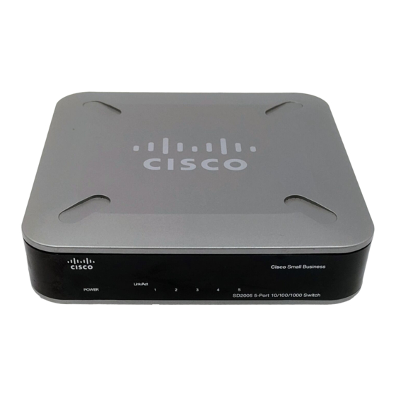
Front Panel
The LEDs are located on the front panel of the Switch.
System—(Green) This LED lights up and remains lit when the Switch is
powered on.
Link/ACT (Ports 1-5)—(Green) Each LED lights up when a connection is made
through its corresponding port. It flashes when the corresponding port is active.
Back Panel
The Power Port and Ethernet network ports are located on the back panel of the
Switch. All ports are auto-negotiating and have automatic MDI/MDI-X crossover
detection.
1-5—These ports connect the Switch to network devices, such as computers.
Power—External power adapter with 12V/0.5A DC output must support 100/
240 V and 50/60 Hz inputs.
The power port is where you will connect the power adapter.
Side Panels
There is a physical security slot located on the side of the Switch. The security
slot is where you can attach a lock to protect the Switch from theft.
Placement Options
Set the Switch on its four rubber feet, or mount the Switch on a wall.
The Switch offers two wall-mount slots, which are the two crisscross slots on
the bottom panel. The measurement between the two slots is 2.52 inches
(64 mm).
Before mounting the switch onto a wall, it is important to consider the following:
Ensure the wall is strong enough to support the switch, a minimum of 1/2" of
•
sheet rock is recommended.
•
Do not operate the switch in an area that has reduced air flow, or exceeds
an ambient temperature of 104º (40ºC).
•
The switch can be mounted either horizontal or vertical.
•
Mounting screws should have a head 5.5mm wide, 2mm deep, and the shaft
of the screw should be at least 13mm long and 2.9mm wide.
To use the wall-mount option, follow these instructions:
S
1
The wall-mount slots are two crisscross slots on the Switch's
TEP
bottom panel. Attach two screws to the wall 64mm apart.
S
2
Maneuver the Switch to insert the screws into the two slots, then slide
TEP
the switch downward onto the screws.
Advertisement

Related Manuals for Cisco SD2005


Summary of Contents for Cisco SD2005
- Page 1 The Switch offers two wall-mount slots, which are the two crisscross slots on detection. the bottom panel. The measurement between the two slots is 2.52 inches Thank you for choosing the Cisco 5-Port 10/100/1000 Switch. The Switch (64 mm). provides non-blocking, wire speed switching for your 10, 100, and 1000 Mbps network clients.
- Page 2 800 553-NETS (6387) Fax: 408 527-0883 Cisco, Cisco Systems, the Cisco logo, and the Cisco Systems logo are registered trademarks or trademarks of Cisco Systems, Inc. and/or its affiliates in the United States and certain other countries. All other trademarks mentioned in this document or Website are the property of their respective owners.