Toyota 2012 Prius Installation Instructions Manual
Softtouch
Hide thumbs
Also See for 2012 Prius:
- Owner's manual (704 pages) ,
- Quick reference manual (32 pages) ,
- Catalog (21 pages)
Advertisement
Quick Links
General Applicability:
Toyota – 2012-2013 Prius/Prius V, 2013 Venza, 2013 Avalon, 2013 Highlander, 2013 Tacoma
For video installation instructions, please visit us online at www.rostra.com.
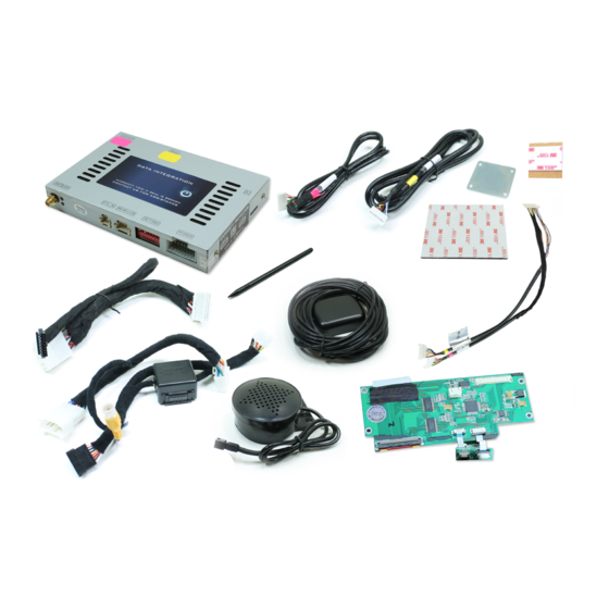
Parts Identification
Vehicle Preparation
Programming Switch Settings
Installation
Parts Identification
Item
Qty.
1
1
2
1
3
1
4
1
5
1
6
1
7
1
8
1
9
1
10
1
Form #5420, 3-20-2013
Rostra Precision Controls, Inc. - 2519 Dana Dr. - Laurinburg, NC 28352 - 800-782-3379 - rostra.com
SoftTouch Navigation System
250-7613 2012-2013 Toyota Camry Installation Instructions
Description
Navigation interface module
LCD IN harness
TP-IN harness
Hardware service parts (VHB tape, metal plate)
Vehicle interface harnesses
Stylus
GPS antenna with magnetic base
GPS speaker
Navigation interface board
LCD-IN/TP-IN Extension Harness
Page 1
Page 3
Page 3
Page 4
Page 1
Advertisement

Related Manuals for Toyota 2012 Prius


Summary of Contents for Toyota 2012 Prius
- Page 1 SoftTouch Navigation System 250-7613 2012-2013 Toyota Camry Installation Instructions General Applicability: Toyota – 2012-2013 Prius/Prius V, 2013 Venza, 2013 Avalon, 2013 Highlander, 2013 Tacoma For video installation instructions, please visit us online at www.rostra.com. Parts Identification Page 1 Vehicle Preparation...
- Page 2 STOP YOU MUST READ THESE WARNINGS AND NOTICE BEFORE PRODUCT HANDLING AND INSTALLATION! PRODUCT AND VEHICLE APPLICATION WARRANTY DISCLAIMER WARNING ! The Navigation Electronic Components are sensitive to Electro- Static Discharge (ESD). DO NOT HANDLE THE NAVIGATION ELECTRONIC COMPONENTS WITHOUT PROPER ESD GROUNDING DURING INSTALLATION.
- Page 3 WARNING To avoid dangerous distractions that may lead to an accident, the driver should never operate the system while the vehicle is in motion. Before installing this product, the seller should inform the end-user of proper use and compliance with the proper instructions and all state and federal laws.
- Page 4 Installation Remove air vent to access upper radio screws. Remove trim pieces to access lower screws. Remove four screws securing radio/screen unit. Release connectors from upper dash trim. Remove upper dash trim from radio. Gently tilt radio away from dashboard. Page 4 ...
- Page 5 Release harnesses from rear of radio/screen. Lift screen away from dashboard. Navigation Interface Module Installation ESD Warning: Do not handle the navigation interface circuitry without taking proper electrostatic discharge precautions making sure both the installer and navigation unit are properly grounded before touching any interior radio or navigation components.
- Page 6 Installer note: To gain more flexibility while Disconnect the large brown ribbon cable from the installing the navigation interface board in the next factory board and insert the ribbon cable from the steps, you can release the tabs to remove the ribbon nav interface board.
- Page 7 Connect LCD-IN/TP-IN Extension Harness to the Route the LCD-IN/TP-IN Extension Harness from navigation interface board. the radio’s interior through the opening in the back of the housing. Attach the included metal plate to the interior of the Place the included GPS antenna atop the mounted vehicle’s dashboard using the supplied double-sided metal plate and allow its magnetic base to secure it tape.
- Page 8 Connect the included speaker to the speaker Connect the speaker extension harness to the extension harness. navigation module. Using the supplied cable ties, mount the navigation Using the supplied alcohol pad, throughly clean the speaker to the dashboard support brackets behind underside of the factory radio and navigation unit.
- Page 9 Connect the yellow and pink color-coded TP-IN and Firmly press the navigation module to the bottom LCD OUT harnesses to the rear of the navigation side of the factory radio allowing the VHB to module. adhere the two together. Connect the power harness from the supplied t- Connect the radio interface plug from the supplied harness to the POWER connector of the navigation t-harness to the backside of the radio.
- Page 10 Turn on the vehicle’s ignition. Press the steering wheel’s phone hang up button for 2 seconds to switch to the navigation interface. Once the steering wheel’s phone hang up button has been pressed, the navigation screen should be displayed. Page 10 Rostra Precision Controls, Inc.